Fuel-Saving Postcapture Detumbling by Dual-Arm Space Robot
Abstract
After the dual-arm space robot captures a noncooperative target, a closed-chain multibody system is formed, making dynamic modeling and detumbling trajectory planning particularly challenging. This paper proposes a novel trajectory planning strategy that guides the combined system into a uniaxial rotational state about its maximum principal inertia axis. Unlike prior work that focuses solely on eliminating the target’s relative motion, our approach additionally drives the closed-chain system into a dynamically favorable uniaxial rotation. This configuration avoids multiaxis coupling and simplifies subsequent stabilization, requiring only unidirectional thruster torque. By reducing the number of required control directions and eliminating complex angular momentum interactions, the subsequent attitude stabilization becomes more fuel-efficient. As a result, the fuel required for postdetumbling control can be significantly reduced. The detumbling process is executed solely by actuating the joints of the dual manipulators without consuming any base thruster fuel. Numerical simulations validate that the proposed strategy effectively establishes the desired rotational mode and that the joint-space tracking controller enables accurate execution of the planned trajectory.
1. Introduction
With the booming expansion of human space exploration, the amount of space junk has increased significantly, including defunct satellites [1], rocket upper stages [2], and lost equipment [3], which are distributed throughout earth orbits, threatening the safe functioning of spacecraft. Active on-orbit capture of space junk is considered a highly feasible approach for mitigating the risk of space collisions, and many scholars have focused on related studies. Various capture techniques have been proposed, such as robotic arms, harpoons, tentacles, and nets [4]. Among these, space robotic arms have drawn particular attention due to their controllability and flexibility in capture operations. Space agencies of several countries have been conducting preresearch or on-orbit demonstrations of capture projects using space robotic arms [5–7]. The technical challenges of on-orbit capture primarily involve path planning and base attitude stabilization in the precapture stage, contact dynamics in the capturing stage, and the detumbling problem of the combined system in the postcapture stage. Particularly in the postcapture stage, the base and the manipulator joints of the space robot acquire specific angular velocities due to the significant residual angular momentum of the target, which may affect communication reliability and structural safety. Moreover, because of the free-floating state of the combined system, the dynamic coupling among components complicates trajectory planning in the detumbling problem. Hence, the postcapture detumbling problem has consistently remained a key research interest.
Given the increasing focus on postcapture detumbling, the deployment of dual-arm space robots is often considered advantageous for on-orbit capture missions. Compared with single-arm space robots, dual-arm ones offer greater operational flexibility since once the combined system is stabilized, one arm can firmly hold the target while the other performs servicing tasks. Huang et al. [8] and Wei et al. [9], respectively, propose attitude takeover control methods for the postcaptured combined spacecraft, while the joints of the manipulators are locked and the combined spacecraft is treated as a single entity. Adaptive coordinated controllers for the postcapture of dual-arm space robots are, respectively, designed by Zhang et al. [10] and Jiao et al. [11], where one arm is designated as the balance arm, thereby underutilizing the full grasping capability of the dual-arm system. However, when both end-effectors firmly grasp the target, the combined spacecraft inherently becomes a closed-chain multibody system. The presence of closed-chain constraints introduces significant complexity in dynamic modeling, trajectory planning, and controller design compared to traditional tree-structured multibody systems. Existing research on dual-arm postcapture detumbling mainly focuses on planar detumbling scenarios involving 3-DOF (degree of freedom) dual manipulators [12–14], while relatively few address three-dimensional detumbling scenarios. Notable exceptions include the work of Yan et al. [15], who proposed a detumbling trajectory optimization method based on the kinodynamic concept, and Zhou et al. [16], who introduced a task compatibility-based detumbling approach with computational efficiency improvement. To address these limitations, this paper proposes a novel strategy for the three-dimensional postcapture detumbling scenario by 7-DOF dual manipulators, with a particular emphasis on saving fuel consumption.
In addition to the dynamic complexity of dual-arm closed-chain systems, energy efficiency is another critical consideration in the design of postcapture detumbling strategies. Space robots operate under strict energy constraints due to limited onboard resources. While previous studies have addressed energy-saving techniques during the capture and detumbling processes, most efforts have focused on reducing the electrical energy consumed by manipulator joint actuators [17–19]. However, unlike electricity, which can be replenished via solar panels, the fuel used by the base thrusters is limited and difficult to resupply. Therefore, saving fuel consumption during on-orbit operations is essential for extending mission lifespans. Despite this importance, existing research has primarily concentrated on fuel-efficient strategies for precapture rendezvous phases [20–22], with relatively limited attention paid to fuel savings during the postcapture stages [23].
To address the need for fuel-efficient detumbling operations highlighted earlier, this study investigates the detumbling strategy for the postcapture combined system. The capture results in a closed-chain multibody system with conserved angular momentum due to the absence of external forces. To enable fuel-efficient postcapture detumbling, the manipulator joints are actuated to redistribute angular momentum and reconfigure the system into a uniaxial rotational state aligned with its maximum principal inertia axis. In this state, all components rotate synchronously with no relative motion, and the system behaves as a single rigid body. This configuration eliminates multiaxis angular momentum coupling, reduces the number of required control directions, and allows subsequent attitude stabilization to rely solely on unidirectional thruster torque, thus significantly improving fuel efficiency. This study presents a trajectory optimization strategy that plans joint motions to realize this rotational state using only motor actuation, and a corresponding joint-space tracking controller is also developed to ensure accurate execution of the optimized trajectories.
- 1.
This study presents an innovative strategy for fuel-efficient postcapture detumbling of dual-arm space robots. The strategy is applicable to the three-dimensional detumbling scenarios involving the combined system with closed-chain constraints and high DOFs.
- 2.
The strategy actively drives the combined system into a uniaxial rotational state about its maximum principal axis through the dynamic effects of manipulator operation without the consumption of base thruster fuel.
- 3.
This strategy achieves uniaxial rotation of the combined system, eliminating multiaxis angular momentum coupling. By using single-direction thrust control, it reduces control complexity and enables fuel-efficient detumbling.
The following is the organization of the paper. Section 2 develops the dynamic equation of the combined system. Section 3 introduces the detumbling strategy including the joint rotation trajectory planning and tracking control method. In Section 4, the effectiveness of the provided strategy is verified through numerical simulations. Finally, conclusions are drawn in Section 5.
2. Dynamic Modeling
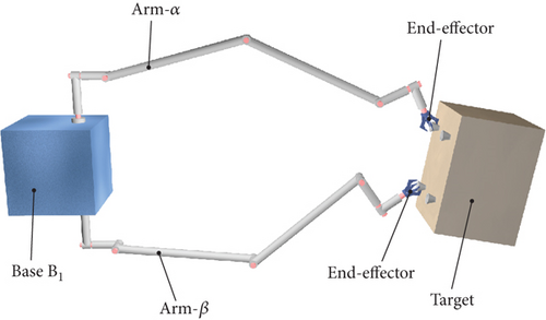
In the postcaptured phase, the target is firmly grasped by the end-effectors of the dual-arm space robot, forming a closed-chain combined system, as shown in Figure 1. This section provides a detailed model description of the combined system and derives the corresponding dynamic equation.
2.1. Model Description
Figure 2 describes the structure of the combined system in detail. Two 7-DOF redundant manipulators, designated as Arm-α and Arm-β, and a free-floating base B1 form the dual-arm space robot. Links B2~B8 belong to Arm-α, and links B9~B15 belong to Arm-β. The captured target is denoted by rigid body B16. The inertial reference frame is denoted by O-XYZ, and the body-fixed reference frame of Bi (i = 1 ~ 16) is represented by oi-xiyizi. The origin oi of each body-fixed reference frame is located at the center of mass (CM) of Bi, and the column arrays ai and bi, respectively, represent the relative positions between the CM of Bi and the joints connected to it.
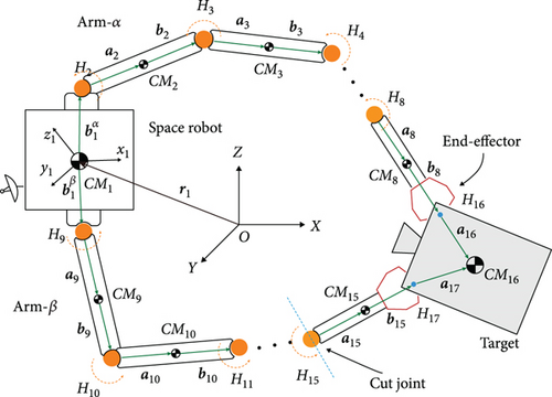
Base B1 is free-floating, and the 6-DOF virtual joint H1 is defined connecting B1 to the origin O of the inertial reference frame. The inner-adjacent joints of links B2~B15 are rotation joints H2~H15, and their rotation angles are denoted as θ1~θ14, respectively. The end-effectors mounted on links B8 and B15 firmly grasp the target B16; thus, joint H16 connecting B8 with B16 and joint H17 connecting B15 with B16 are assumed as fixed joints.
2.2. Dynamic Equation
2.3. Direct-Inverse Mixed Dynamics
In the trajectory optimization process presented in the following section, the rotation trajectories of a subset of joints are predefined, while the final base poses and the rotation trajectories of the remaining joints need to be determined. To address this problem, the direct-inverse mixed dynamics is introduced in this section.
3. Detumbling Strategy
In this section, a fuel-efficient detumbling strategy is developed to guide the postcapture combined system into a uniaxial rotation state. First, the joint trajectories are parameterized to enable efficient formulation of the optimization problem. Then, an optimization framework is proposed to plan joint motions that reconfigure the system into uniaxial rotation without using base thruster fuel. Finally, a trajectory tracking controller is designed to ensure accurate execution of the planned trajectories.
3.1. Trajectory Planning Method
The combined system depicted in Figure 2 is a typical closed-chain multibody system. The dual manipulators of the combined system have 14 rotation joints, but only eight of them are independent due to the existence of the closed-chain constraints. Therefore, we only need to designate eight joints to plan their rotation trajectories θd(t), with the rotation trajectories of the remaining joints being uniquely determined through the closed-chain constraints. To facilitate the description of the trajectory optimization problem, it is essential to parameterize the rotation trajectories θd(t) of the controlled joints.
It can be observed from Equations (30)–(34) that the coefficients ai0~ai2 are determined by the initial conditions of the joint rotation, while the coefficients ai3~ai5 depend on the values of ai6 and ai7. Namely, the time-varying trajectory of the i-th joint can be fully characterized by the coefficients ai6 and ai7.
Considering the direct-inverse mixed dynamics equation introduced in Equation (22), the position and attitude variables of the base of the dual-arm space robot are q1, the planned trajectory θd of the selected joints is q2, and the time-varying trajectory of the remaining joints is q3. Given a pair of coefficients ai6 and ai7, a group of time-varying trajectory of θd, , and can be determined. Subsequently, the final state q1(tf) and of the base, as well as the time-varying trajectory q3(t) of the remaining joints, can be calculated by solving Equation (22). Apparently, the final state q1(tf) and of the base depends on the specific values of ai6 and ai7.
By substituting Equation (39) into Equation (38) and noting that Js is a positive definite matrix, it can be inferred that , indicating that the single entity is in a uniaxial rotating.
The optimal detumbling trajectory can be obtained by using the PSO algorithm [26] to solve the optimization problem, and the flowchart of the optimization process is shown in Figure 3.

3.2. Tracking Control Method
This section presents the design of the controller to actuate the joints and track the trajectory optimized in the previous section.
When KP and KD are assigned as positive definitive matrices, Equation (45) is asymptotically stable, ensuring the convergence of the errors e(t).
4. Numerical Simulations
To validate the efficacy of the introduced technique towards the detumbling of the closed-chain combined system depicted in Figure 1, numerical simulations are conducted in this section. The structural parameters of the system are provided in Table 1.
| Body | mi (kg) | (m) | (m) | (kg·m2) | ||||||
|---|---|---|---|---|---|---|---|---|---|---|
| B1 | 500 | — | — | — | 0.4 | 0 | 0.8 | 240 | 240 | 240 |
| B2 | 5.2 | 0 | 0 | 0.25 | 0.05 | 0 | 0.15 | 0.06 | 0.06 | 0.01 |
| B3 | 5.2 | 0 | 0 | 0.15 | 0.05 | 0 | 0.15 | 0.06 | 0.06 | 0.01 |
| B4 | 24.07 | 0 | 0.8 | 0.05 | 0 | 0.8 | 0.05 | 4.52 | 0.04 | 4.52 |
| B5 | 24.07 | 0.8 | 0 | 0.05 | 0.8 | 0 | 0.05 | 0.04 | 4.52 | 4.52 |
| B6 | 5.2 | 0 | −0.15 | 0.05 | 0 | −0.15 | 0 | 0.06 | 0.01 | 0.06 |
| B7 | 5.2 | −0.15 | 0 | 0.05 | −0.15 | 0 | 0 | 0.01 | 0.06 | 0.06 |
| B8 | 12.84 | 0 | 0 | 0.3 | 0 | 0 | 0.3 | 0.16 | 0.16 | 0.03 |
| B9 | 5.2 | 0 | 0 | −0.25 | 0.05 | 0 | −0.25 | 0.06 | 0.06 | 0.01 |
| B10 | 5.2 | 0 | 0 | 0.15 | 0.05 | 0 | 0.15 | 0.06 | 0.06 | 0.01 |
| B11 | 24.07 | 0 | 0.8 | 0.05 | 0 | 0.8 | 0.05 | 4.52 | 0.04 | 4.52 |
| B12 | 24.07 | 0.8 | 0 | 0.05 | 0.8 | 0 | 0.05 | 0.04 | 4.52 | 4.52 |
| B13 | 5.2 | 0 | 0.15 | 0.05 | 0 | 0.15 | 0 | 0.06 | 0.01 | 0.06 |
| B14 | 5.2 | −0.15 | 0 | −0.05 | −0.15 | 0 | 0 | 0.01 | 0.06 | 0.06 |
| B15 | 12.84 | 0 | 0 | −0.3 | 0 | 0 | −0.3 | 0.16 | 0.16 | 0.03 |
| B16 | 1000 | 0.4 | 0.4 | 0.8 | — | — | — | 420 | 420 | 420 |
The combined system has 14 revolute joints, but the existence of closed-chain constraints leads to only eight DOFs relative to the base. Therefore, it is appropriate to select eight drive joints. If the number of drive joints exceeds eight, the system becomes overconstrained, leading to potential kinematic violations. Conversely, if fewer than eight drive joints are selected, the system is underconstrained, and when the drive joints stop rotating at the final stage, the rotation of the remaining joints may not stop.
Numerical simulations are provided in two cases. In Case 1, joints H2~H4, H6~H9, and H12 are selected as the controlled joints for detumbling operation, and the range of the rotation angle of each joint is ±15°. In Case 2, the initial moment of momentum is larger than Case 1, and joints H2~H9 are selected as the controlled joints with the range of the rotation angle extending to ±30°. The simulation results show that the presented strategy is effective for different controlled joints and different initial angular momentum in three-dimensional detumbling problems with closed-chained constraints in the combined system.
4.1. Case 1
In Case 1, each coordinate axis of the inertia reference frame is aligned with the corresponding axis of the base-fixed reference frame, and both reference frames share the same origin. The initial angular velocity of the base-fixed coordinate system is [3.14,−5.28, 1.69]T × 10−3 rad/s, and the initial translational velocity of the origin of is [3.85, 1.98, 0.72]T × 10−2 m/s. Joints H2~H4, H6~H9, and H12 are designated for trajectory planning, and the trajectories of the remaining joints can be uniquely solved once the trajectories of the selected joints are determined, considering the closed-chain constraints. The initial angle and angular velocities of the selected joints are, respectively, [−0.52, 0,−2.62, 2.09, 2.62, 0, 0,−0.52]T rad and [−6.25, 1.14,−2.42, 1.83,−2.74, 4.62, 1.96,−1.75]T × 10−2 rad/s. For the remaining joints H5, H10, H11, and H13~H15, the initial angle and initial angular velocities can be, respectively, solved as [0, 2.73,−1.75, 2.69, 0, 0]T rad and [3.40,−2.89, 5.23,−5.66,−4.73, 0.41]T × 10−2 rad/s by inverse kinematics. The angular velocity of the target can be solved as [7.13,−0.07,−5.32]T × 10−3 rad/s through the velocity recursion of the base and the joints of Arm-α.
In this case, the rotating duration of the selected joints H2~H4, H6~H9, and H12 is set as 60 s. Their rotation trajectories are planned using the presented trajectory planning method, which is optimized by the PSO algorithm. In the PSO optimization, the number of particles is N = 100, the inertial coefficient is w = 0.8, and the learning coefficients are c1 = c2 = 1.5. The optimization is considered to reach the goal when the cost function falls below J = 10−8. The optimal trajectories planned for the selected joints are depicted as blue curves in Figure 4, as well as the rotation trajectories of the remaining joints following the rotation of the selected joints. The variation trends of the angular velocity of the combined system are expressed by that of the base, as depicted by the blue curves in Figure 5. The angular velocity array in Figure 5 is calculated in the final principal axis coordinate system, and thus Figure 5 clearly demonstrate that and effectively converge to 0.
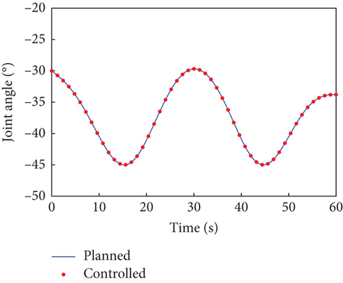
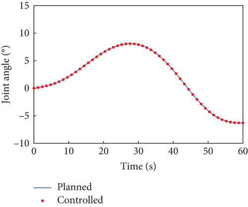
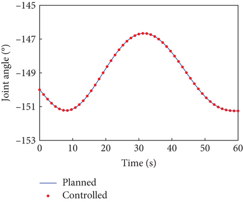
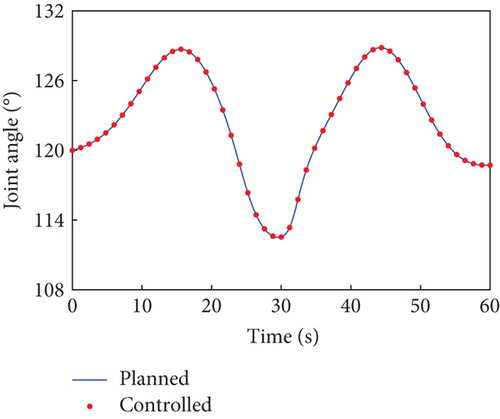
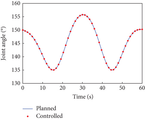
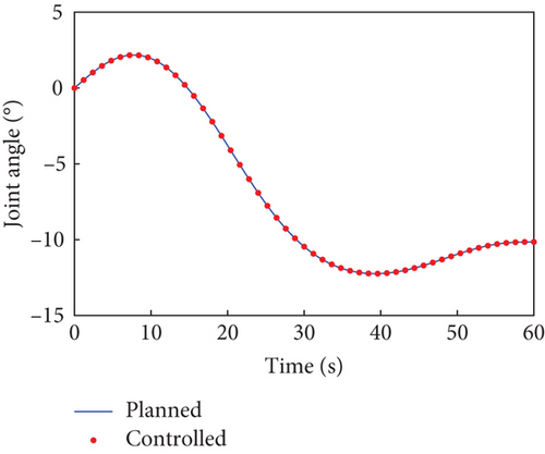
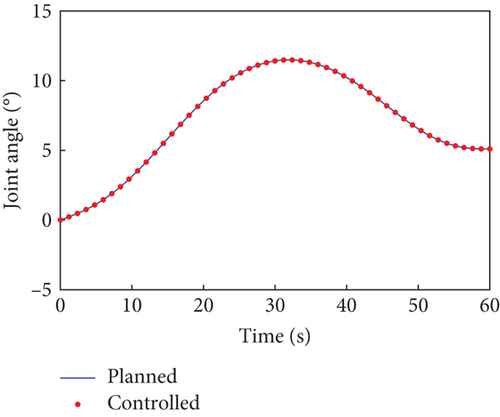
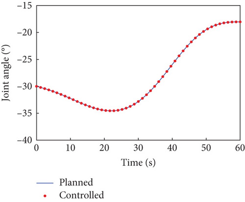
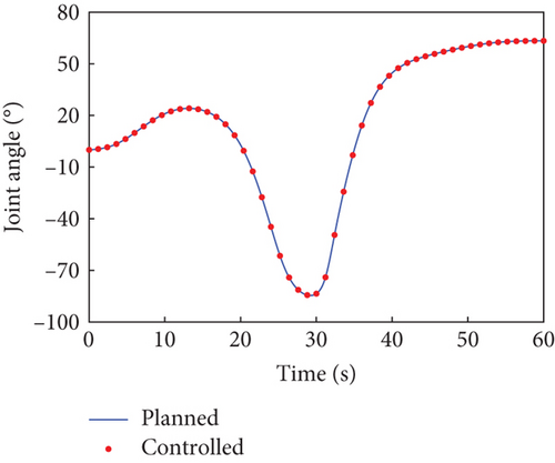
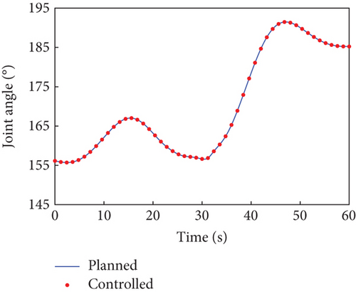

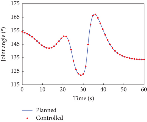
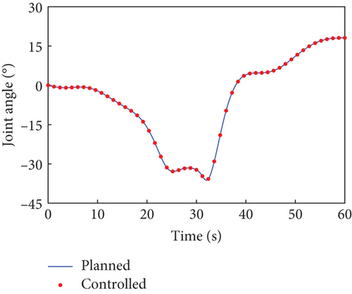
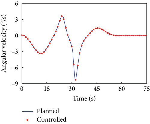
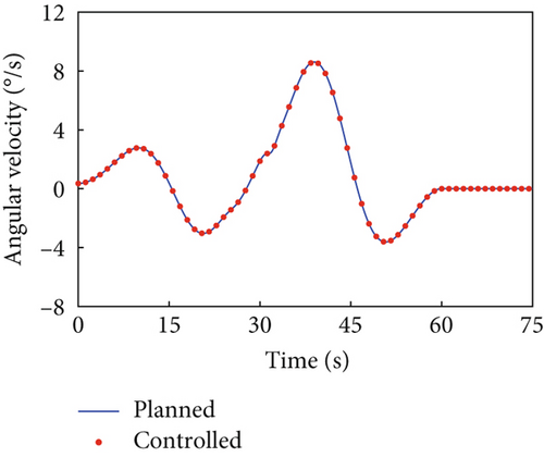
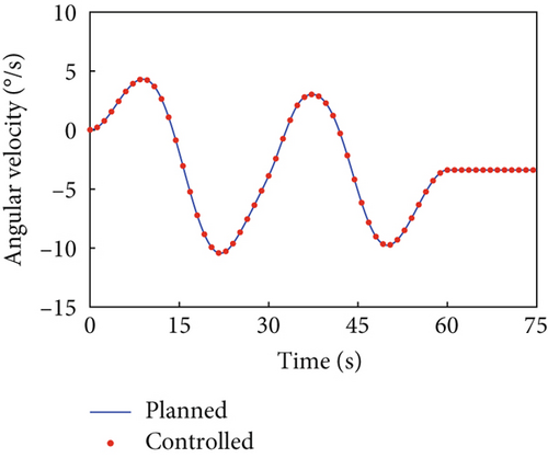
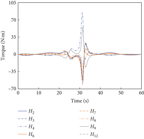
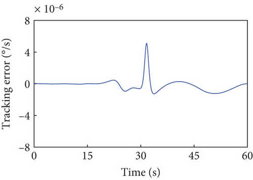
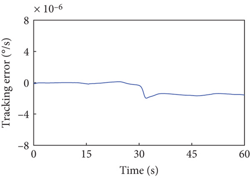
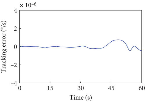
According to Section 3.2, by assigning Kp = 50 × I8 and Kd = 5 × I8, the tracking controller is designed to actuate the selected joints H2~H4, H6~H9, and H12 to rotate along the planned trajectories, and the control torques of the controlled joints are shown in Figure 6. The tracking effect of the selected joints is depicted by red dots in Figure 4, and the motions of the base and the remaining joints H5, H10, H11, and H13~H15 under the dynamic coupling with the selected joints are depicted by red dots in Figures 4 and 5, respectively. The red dots fit well with the blue curve in both Figures 4 and 5, and the error between the variation of base angular velocities in the principal axis under the planned trajectory and that driven by the tracking controller is given in Figure 7. The error is within 5°/s × 10−6, and the precise tracking ability of the controller can be demonstrated. At the final moment, we have , , and , which denote the approximate confirmation that the combined system is rotating uniaxially.
4.2. Case 2
The initial pose and configuration of the combined system remain unchanged in Case 2, but the combined system has a higher moment of momentum. Manipulator joints H2~H9 are selected as the controlled joints. The initial angular velocity of the base and the selected joints H2~H9, respectively, changes to [5.22,−7.17, 3.55]T × 10−3 rad/s and [−13.98, 6.12,−5.21, 5.67,−5.82, 6.80, 5.81,−1.75]T × 10−2 rad/s. The initial angular velocities of the remaining joints, H10~H15, can be calculated as [15.21,−3.48, 7.29,−9.17,−11.85,−7.19]T × 10−2 rad/s through the inverse kinematics. The angular velocity of the target can be solved as [15.94,−3.53, 15.09]T × 10−2 rad/s through the velocity recursion.
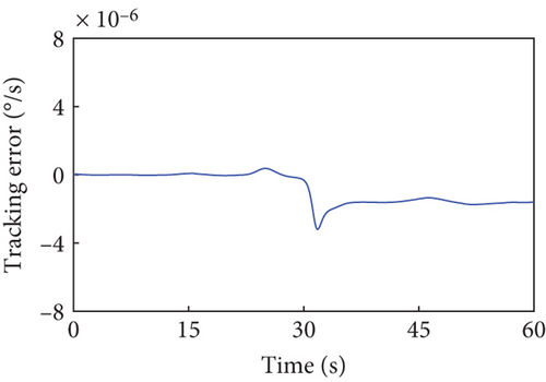
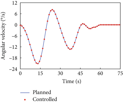
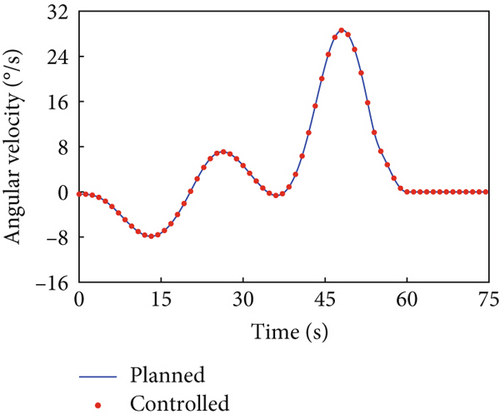
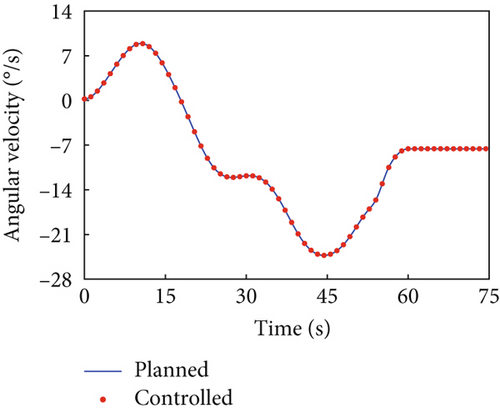
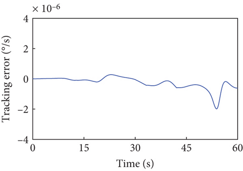
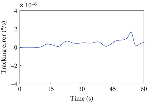
The parameters for the trajectory optimization and tracking controller remain unchanged. Affected by the dynamic coupling with the joint rotations along the planned trajectory, the variation in base angular velocity is depicted by the blue curves in Figure 8. The variation curve of the base angular velocity affected by the joint motors actuated by the tracking controller is depicted by the red dots in Figure 8. The error between the variation of base angular velocities in the principal axis under the planned trajectory and that driven by the tracking controller is given in Figure 9, demonstrating that the controller still maintains precise tracking performance. At the final moment, the uniaxial angular velocity of the combined system is , while the other two components of the angular velocity array is and , showing the capability of the proposed strategy to handle a higher initial angular momentum in the combined system.
4.3. Robustness Evaluation of Inertia Parameter Uncertainty
This section evaluates the robustness of the presented detumbling strategy against inertia parameter uncertainties by extensive simulations. We introduce up to 3% random estimation error to the inertia parameters of the combined system, and the system with corresponding initial conditions is driven by the tracking controller along the original detumbling trajectories planned in Case 1 and Case 2, respectively. The simulation results are given in Figures 10 and 11 by showing the variation curves of the base angular velocities in the principal axis coordinate system with different estimation errors. According to the definition, the principal axis coordinate system corresponding to each curve varies with the inertia parameter errors and the final configuration. The results show that when the estimation error of the inertial parameters is less than 3%, our detumbling strategy can still achieve satisfactory results.
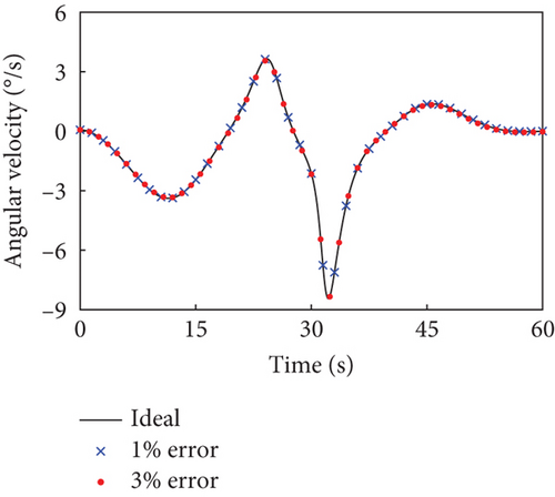
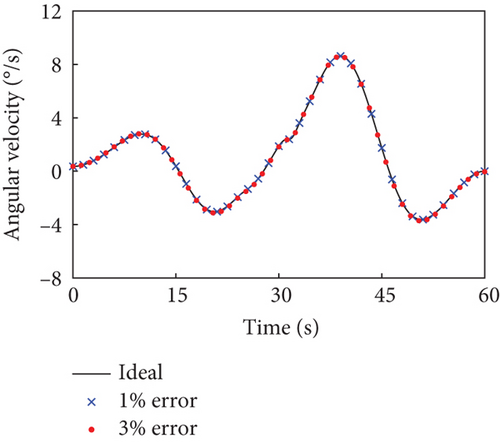
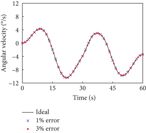
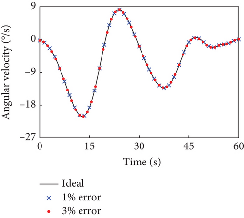
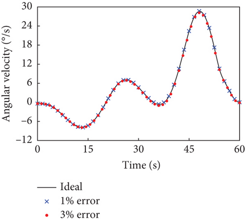
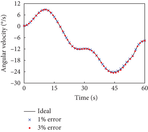
When the random estimation error is 1%, the final absolute angular velocity in the principal axis coordinate system is °/s in Case 1 and °/s in Case 2. When the random estimation error is up to 3%, there is °/s in Case 1 and °/s in Case 2. In both the above cases, the combined system can be driven to the uniaxial rotation state about its maximum principal axis quite well, which denotes that the detumbling strategy has certain robustness.
5. Conclusion
This paper presents a fuel-saving detumbling strategy for dual-arm space robots capturing noncooperative targets. By utilizing manipulator joint dynamics powered solely by renewable electricity, the proposed method actively drives the closed-chain combined system into a stable uniaxial rotation about its maximum principal axis. This innovative approach offers two key advantages: (1) The unified single-axis rotation state enables simplified attitude control requiring only unidirectional thrust. (2) Fuel efficiency is achieved by eliminating the demands for multiaxis stabilization. Numerical simulations demonstrate the strategy’s effectiveness in solving three-dimensional detumbling problems for high-DOF space combined systems, highlighting its potential for on-orbit servicing missions.
Conflicts of Interest
The authors declare no conflicts of interest.
Funding
This research was supported by the National Natural Science Foundation of China (10.13039/501100001809) (12172215 and 12172214).
Open Research
Data Availability Statement
The data that support the findings of this study are available from the corresponding authors upon reasonable request.


