Exploring In-Orbit Operations: Assessing Performance and Fault Management of the Student Small Satellite-1 (SSS-1)
Abstract
Small satellites represent a pivotal advancement in space technology, offering versatile platforms for conducting educational missions with reduced costs. Initiated by the Asia-Pacific Space Cooperation Organization (APSCO), the Student Small Satellite-1 (SSS-1) mission exemplifies this paradigm. SSS-1 is designed to validate the deployment of the coilable mast and conduct diverse space experiments in orbit. This paper provides a detailed exploration of the SSS-1 space experiments and the fault handling procedures. Firstly, the overview of SSS-1 is presented in this paper. Next, it details the results of various space experiments, including space imaging, remote sensing, electrical propulsion system tests, and Automatic Dependent Surveillance-Broadcast (ADS-B) signal acquisition. The in-orbit performance of the platform subsystems is also delivered in this paper. Thus, the successful design and development of SSS-1 are explained and validated. Despite encountering challenges such as a single event upset (SEU) and attitude determination and control subsystem (ADCS) fault, SSS-1’s overall performance remained robust, and the fault’s influence was greatly reduced with the manual control. This study not only highlights the technological advancements achieved by the SSS-1 project but also provides valuable insights for future educational small satellite missions.
1. Introduction
Due to the advantages such as light weight, small size, flexible launch methods, short development cycle, and low cost, small satellites and cube satellites have received increasing attention. As ideal platforms for testing new ideas and devices in space missions, the number of such satellite launches has rapidly increased in recent years [1, 2]. Besides, their quick turnaround times and affordability make them attractive for educational institutions and foster renewed interest in scientific, commercial, and military applications [3].
Many countries have supported their space education via small satellite programs. In particular, UWE program (University Würzburg’s Experimental satellite program) is one notable program in Germany for the educational purpose. Student-built picosatellites like UWE-1, UWE-2, and UWE-3 have successfully operated in orbit since 2005, focusing on “internet in space,” attitude determination, and attitude control, respectively [4, 5]. The most recent satellite, UWE-4, was launched as the first demonstration of collision avoidance and orbit control using electric propulsion on a 1 U CubeSat, exemplifying the step-by-step development of formation flying technologies for picosatellites under the UWE program [6, 7]. Surrey University has a rich history of satellite innovation, which launched the pioneering reprogrammable satellite UoSAT-1 in 1981, which featured onboard reprogrammable microcomputers and marked a significant advancement in civilian satellite technology. This tradition of innovation continues with projects like the AAReST mission, a collaboration with CalTech, JPL, and IIST, aimed at creating a reconfigurable space telescope using a cluster of CubeSats equipped with a deployable boom and adjustable 10-cm-diameter circular mirrors [8]. In China, Tsinghua University use the Q-Sat mission to achieve remarkable precision in measuring long-wavelength gravity fields and upper atmosphere density while also pioneering key technologies such as onboard artificial intelligence processing in educational manner [9, 10]. Besides, Harbin Institute of Technology launched ASRTU microsatellite in 2023 implements a tailored health management approach for its attitude control system, encompassing sensor configuration, actuator design, attitude operation modes, and fault simulation verification strategies [11].
The Student Small Satellite-1 (SSS-1) is also an educational-aimed satellite, and it is the main satellite of the Student Small Satellite (SSS) project, initiated by the Asia-Pacific Space Cooperation Organization (APSCO). This project is aimed at improving the satellite research, development and application capabilities of its members, and the level of space technology education. It is also a key project in the “Belt and Road” international space development strategy of the China National Space Administration (CNSA) and has been listed in the white paper of CNSA in 2016 and 2021. Besides China, there are Turkey, Thailand, Peru, and Pakistan, totaling eight countries participating in this program.
The APSCO SSS project consists of a 30 kg small satellite SSS-1 and two 3 U cube satellites (SSS-2A/2B). These three satellites jointly complete multiple technical verification tasks including in-orbit deployment of a new deployment mechanism, ground remote sensing, and inter-satellite communication [12]. Under the leadership of Beihang University (BUAA), SSS-1 is the primary satellite of the SSS project, and SSS-2A/2B are designed by Shanghai Jiao Tong University and Turkish Space Agency, separately. The Beihang team collaborates with university teams from member countries at home and abroad and is also responsible for the satellite design, main subsystem design and development, and final assembly integration test (AIT) of the small satellite SSS-1. In addition, the Beihang team was also responsible for implementing frequency point declaration, carrier rocket loading, and launch permits for the three satellites. The SSS project satellites were successfully launched on October 14, 2021, setting a precedent for international cooperation in small satellite research and development between Chinese and foreign universities.
This paper is organized as follows: Section 2 provides an overview of the SSS-1 satellite, detailing its design, mission objectives, and technical specifications. Section 3 describes the in-orbit experiment of SSS-1, including its coilable mast and space camera (SC), remote sensing camera (RC), Automatic Dependent Surveillance-Broadcast (ADS-B), and electric propulsion system. The performance of satellite platform is also briefed in this section. Section 4 presents single event upset (SEU) and attitude determination and control subsystem (ADCS) fault during SSS-1’s in-orbit operation. The fault analysis, handling strategy, and the related effectiveness are also detailed in this section. Section 5 concludes this paper.
2. SSS-1 Satellite
2.1. Payloads of SSS-1
The SSS-1 satellite consists of five main payloads, that is, a coilable mast, a SC, a RC, an ADS-B receiver, and an electric propulsion system. The deployable coilable mast is a space extension mechanism with an extension-to-compression ratio of 20:1 or higher [13]. It is usually stowed in a compact space and deployed after entering orbit, used for satellite attitude pointing and stabilization or to extend certain sensitive instruments or sensors away from the satellite body to reduce the impact of the satellite’s electromagnetic characteristics on these sensitive devices. The coilable deployable mast is shown in Figure 1. And it is independently developed by BUAA, acting as a key in-orbit verification payload of the SSS-1 satellite. To record the expansion process of the coilable mast, a wide field SC is equipped to SSS-1. The sensor of this camera is IMX252, and the focal length of the lens is 24 mm. The coilable mast was deployed on October 14, 2021, and some further experiments are carried out via SC. The results of these experiments are detailed in Reference [12]. Another camera equipped by SSS-1 is a RC with the 1080P resolution, and its normal ground resolution could achieve about 50 m.

Besides, SSS-1 also has ADS-B, which is a new air traffic management technology currently adopted worldwide. The electrospray thruster is another payload designed by Beihang University, acting as the deorbit device for SSS-1. Known for its low power consumption, compact structure, flexible control, and high reliability, it provides a new solution for the active orbit adjustment and attitude control needs of SSS-1. The design specifications of the SSS-1 are shown in Table 1.
| Units | Specifications | Value |
|---|---|---|
| Coilable mast | Mass | ≤ 0.20 kg |
| Expanded length | 2 m | |
| Space camera | Mass | ≤ 0.20 kg |
| Power | ≤ 4 W | |
| Horizontal half angle of view | 50° | |
| Vertical half angle of view | 34° | |
| Resolution | 1920∗1080 | |
| Remote sensing camera | Mass | ≤ 0.60 kg |
| Power | ≤ 5 W | |
| Horizontal half angle of view | 5.50° | |
| Vertical half angle of view | 3.09° | |
| Ground resolution | 20 m@500 km | |
| ADS-B receiver | Mass | ≤ 0.80 kg |
| Power | ≤ 3 W | |
| Processing capacity | ≥ 0.60 kg | |
| Electric propulsion system | Mass | ≤ 1 kg |
| Power | ≤ 5 W | |
| Thrust | ≤ 80 μN | |
| Energy conversion rate | ≤ 10% | |
2.2. Platform of SSS-1
The SSS-1 satellite consists of six subsystems, namely, the structural subsystem, thermal control subsystem (TCS), ADCS, on-board data handling subsystem (OBDH), electrical power supply subsystem (EPS), and telemetry, tracking, and command subsystem (TT&C). The orbit type of SSS-1 is sun synchronous orbit (SSO) with the local time of the descending node being 18:00. Table 2 provides the platform properties of the SSS-1 satellite.
| Name | Properties | |
|---|---|---|
| Mass (including payloads) | ≤ 30 kg | |
| Envelope size | ≤350 mm × 350 mm × 650 mm | |
| Power consumption (including all payloads) | ≤30 W | |
| ADCS | Sun-pointing mode (SPM) | Determination accuracy ≤ 1° (3σ) |
| Pointing accuracy ≤ 3° (3σ) | ||
| Angle stability ≤ 0.2°/s (3σ) | ||
| Attitude maneuver | 30°/120 s | |
| OBDH | Power consumption | ≤ 1.5 W |
| Processor architecture | ARM | |
| EPS | Solar array | Power generation ability ≥ 30 W |
| Battery pack unit | Normal mode operation ≥ 3 h | |
| Minimum system mode operation ≥ 24 h | ||
| TT&C | UHF (telemetry) | Central frequency: 435.750 MHz |
| Code rate: 4800/9600 bps | ||
| Band width: ≤ 16 kHz | ||
| Error rate: 1 × 10⁻⁵ | ||
| VHF (remote control) | Central frequency: 145.855 MHz | |
| Code rate: 1200 bps | ||
| Bandwidth: ≤ 16 kHz | ||
| Error rate: 1 × 10⁻⁶ | ||
| S (data transmission) | Central frequency: 2405.100 MHz | |
| Code rate: 100 kbps | ||
| Bandwidth: ≤ 200 kHz | ||
| Error rate: 1 × 10⁻⁶ | ||
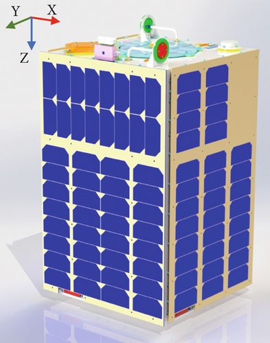
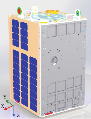
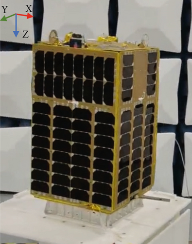
Figure 2 illustrates the flight model of the SSS-1 satellite, showcasing two figures of the CAD design model (Figure 2a,b) and a real photograph (Figure 2c). The body frame of SSS-1 is defined such that the +Y-axis points toward the sun, the +Z-axis points toward the earth, and the +X-axis is oriented according to the right-hand rule. The solar array of SSS-1 is body-mounted, with the sun-pointing panel (+Y panel) using 48 units (8 units in series, 6 in parallel) and the +X and −X panel using 32 units (8 units in series, 4 in parallel) [14]. Communication antennas for UHF and VHF are installed at the bottom of the ±X and ±Y panels, and S band antennas are on the ±Z panels. The coilable mast and SC are mounted on the −Z panel, and the RC is on the +Z panel. The expand direction of the coilable mast is the −Z direction, and the deployment procedure is designed to be recorded by the SC. The electric propulsion system is installed on the −Y panel, and its thruster nozzle can be seen in Figure 2b.
3. In-Orbit Operation and Space Experiment Missions
So far, SSS-1 has successfully executed its designated missions, which encompass deploying a coilable mast, conducting remote sensing experiments, and executing various space experiments. The satellite’s platform system design, payload design, and the latest space experimental results have been thoroughly evaluated, showcasing its successful performance in space.
3.1. Coilable Mast and SC
The coilable mast is a critical in-orbit verification payload of SSS-1. Designed to be compactly stored within a limited cylindrical space with less than 25 cm length, it can deploy to 2 m and boast a stretch-to-compression ratio up to 20:1. The deployment of the coilable mast had successfully accomplished under the ground command control at 18:21 on October 16, 2021. The satellite’s SC captured the entire deployment process, providing valuable data for future satellite design and development. And all data were transmitted to the ground station through S-band antennas in WIFI channel (2.4 GHz) for decoding, showcasing the satellite’s capability in data receiving and processing. The timeframe of the mast’s deployment is further discussed in [12].
With the deployed coilable mast, the SSS-1 team also conducted a series of experiments, including the attitude control of the SSS-1 and the photo imaging of other space targets (such as the moon and the earth). Due to the bending and torsional modes of the coilable mast at low frequencies, the attitude tracking model of a “rigid-flexible-rigid satellite” is formulated especially for SSS-1. This method employs an observer-based compensator and a modified proportional-derivative controller to achieve high-accuracy attitude tracking and vibration suppression for SSS-1 with a coilable mast [15, 16].
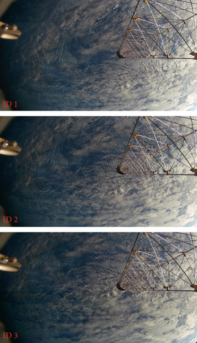
To verify the effectiveness of the ADCS of SSS-1, in November 20, 2021, SSS-1 carried out an attitude maneuver. During this, momentum wheels were employed to rotate the satellite 180° and point the coilable mast toward the ground. The SC took several photos and transmitted them to the Beihang ground station. These photos are shown in Figure 3 with photo ID labeled. The time interval of each photo is about 15 s. We could clearly see the movement of SSS-1 through the background of the clouds on the earth, which meets the orbit characteristics of SSO.
With this mission accomplished, the SSS-1 team planned to take a group photo of the coilable mast and the moon. To accomplish this task, our team proposed a new arrangement: maintaining the ADCS in the sun-pointing mode (SPM) and using the property of the SSO to wait for the opportunity to capture the moon inside the field of view of the spatial camera. Considering the layout of the SSS-1, we noticed that there is a high intensity of sunlight at the top of the coilable mast; thus, the position of the moon should avoid the central area of the SC’s field of view. According to the orbital simulation, we finally selected August 8, 2022, 18:36:00 UTC to carry out this mission.
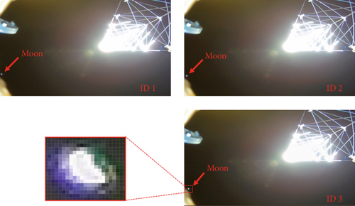
After processing with image processing software, the pixel area occupied by the moon can be determined as 10 × 9, which fully conform to the theory calculations.
3.2. RC
Beginning in March 2022, the SSS-1 satellite initiated functional verification of its RC. So far, we have imaged several high-latitude areas, including the Arctic islands, Turkey Strait, and the area near Alaska. Since a dawn–dusk orbit is assigned to SSS-1, the imaging parameters, especially the solar altitude, are carefully considered. To acquire more sunlight for imaging and get a relatively good imaging quality, the imaging time is often selected to be in summer or winter. Table 3 shows the parameters for the RC for imaging. Figure 5a,b shows the photos of Turkey Strait and the Arctic islands. These images show that the function of the RC is well verified.
| Number | Imaging time (UTC) | Location | Longitude | Latitude | Solar altitude |
|---|---|---|---|---|---|
| 1 | May 7, 2022, 21:39:42 | Turkey strait | 42.053°N | 28.764°E | 6.9° |
| 2 | May 11, 2022, 18:30:14 | Arctic islands | 75.61°N | 96.82°W | 10.1° |
| 3 | June 24, 2023, 13:07:27 | Alaska | 63.04°N | 135.21°W | 15.5° |

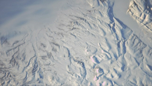
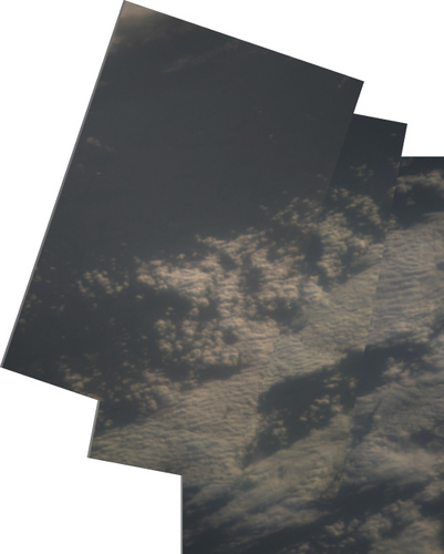
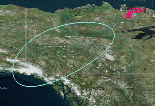
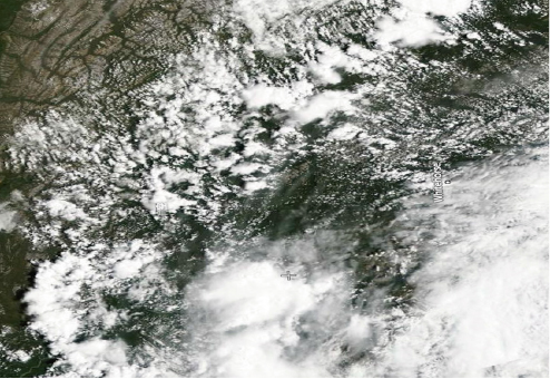
Figure 6a is an assembled image consisting of three sequential photos, with the time interval between each photo being about 3 s. The stitched visualization reveals distinct cloud formations and maritime features through overlapping image registration analysis. Due to the faults of ADCS (will be detailed in Section 4), we could only infer the imaging area, as Figure 6b shows. It is worth noticing that a reference data source was found by our team on the Zoom Earth website, and we found the corresponding meteorological satellite cloud chart shown in Figure 6c [19]. Key geophysical features in Figure 6c, including the cumuliform structures in the southeastern quadrant and pelagic patterns in the northwestern sector, demonstrate spatial consistency between the SSS-1 observations and satellite benchmarks. The above sequentially captured images of the Earth’s surface demonstrate the SSS-1’s capability in remote sensing. The images captured by the camera were of high quality and provided valuable data for environmental monitoring, disaster relief, and scientific research.
3.3. ADS-B
The ADS-B system, commonly used by civil aviation aircraft, automatically broadcasts its attributes, status, and position information periodically. These ADS-B signals are received by ground air traffic control systems, airborne aircraft, or satellite-based receivers. When received by airborne aircraft, ADS-B signals enable mutual surveillance, helping to avoid collisions. The ground air traffic control systems use these signals to monitor aircraft and manage flight safety. However, due to the limited receiving range of ground stations, satellite-based ADS-B receivers are gaining more attention for aircraft monitoring and management. This capability is validated by the ADS-B receiver on SSS-1.
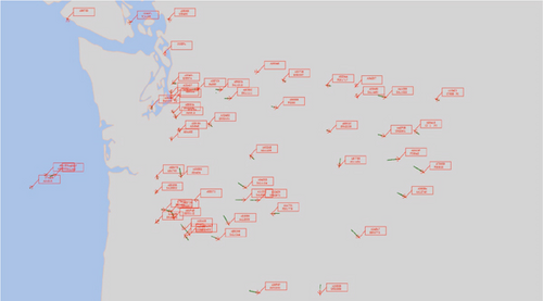
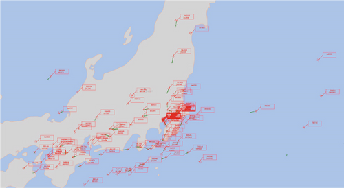
The SSS-1’s ADS-B receiver successfully received and stored multiple flight information data. Due to the mass and power constrain, the ADS-B receiver equipped in the SSS-1 does not process ADS-B data on board and all received data will be transmitted to the ground station for further analysis. By July 2023, SSS-1 has received over 1 million ADS-B information, and about 10% have been transmitted to the ground and successfully decoded. Some decoded data information for the west coast of the United States, the Philippines, and the Tokyo of Japan are shown in Figures 7a, 7b, and 7c, respectively. In these figures, the flight position and their corresponding flight number are marked. Some flights’ signal had lasted for a few minutes, and their paths are shown with green solid lines. These show that SSS-1 has the capability in receiving and processing real-time air traffic data, which demonstrates that small satellite–based air traffic management is possible. This experiment has also significant implications for space-based or microsatellite-based air traffic management and collision avoidance systems.

3.4. Electric Propulsion System
Electric propulsion system serves as both a deorbit equipment and a payload of SSS-1. On May 17, 2022, at 10:13:21 UTC, the igniting command of electric thrusters had been transmitted to SSS-1. The telemetry showed that a voltage of 2.52 kV had been generated, and the inner current had come up to 200 μA. Besides, according to the telemetry, the duty cycle of the electric propulsion system was 45%, which shows that the electric propulsion is electrically neutral [20]. These telemetry readings confirmed the successful ignition of the electric propulsion system developed by Beihang University. For this inaugural firing, a duration of 30 s was preprogrammed, with the satellite’s attitude behavior being closely observed and recorded.
Given the normal thrust produced by the electric propulsion system is only approximately 30–40 μN, a novel thrust estimation method based on attitude changes has been employed to validate its efficacy. As depicted in Figure 2, the electric propulsion thruster is installed at the −Y panel of the SSS-1. The precise position of the thruster head with respect to the center of the gravity (COG) of the SSS-1 is measured at [lx, ly, lz] = [71.3, −166.4, −56.1] mm. It is evident that the electric propulsion system will not only generate thrust but also a torque to the SSS-1. This torque will be treated as part of the disturbance which only exists during the ignition period. If the ADCS controls the attitude of the SSS-1 to be stable, the disturbance torque will be counteracted and by the actuator of ADCS. By monitoring the status of the actuator, that is, the speed of the reaction wheels, the thrust of the electric propulsion can be estimated.
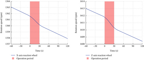
With Equations (8) and (9), it is calculated that the thrust of electric propulsion system F is 31.06 and 32.38 μN, respectively. A mere 4.3% discrepancy exists between these two outcomes, demonstrating good consistency. Therefore, the mean value of the above calculated thrust is regarded as the experiment results, yielding F = 31.72 μN. Besides, the in-orbit verification results show a mere 5.7% deviation from the design specifications, confirming the in-orbit test as a resounding success.
3.5. Evaluation for the Satellite Platform
The continuous monitoring of the SSS-1 platform status has been carried out since its launch into orbit. The satellite’s health is indicated by the normal functioning of its subsystems, particularly the EPS and TCS.
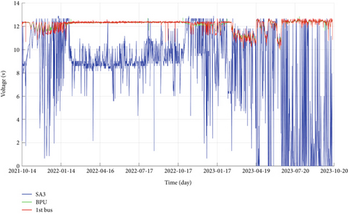
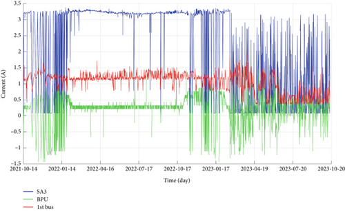
The SSS-1 satellite’s EPS has maintained optimal performance throughout its 2-year operational period. Figure 9a,b illustrates the variation of the satellite’s voltage and current change of some key equipment over the 2 years, respectively. The Solar Array 3 (SA3) is the sun pointing solar array, which is pointing to the sun. The battery pack unit (BPU) is energy storage equipment of EPS, and the first bus (First Bus) is the 12 V bus, which acts as the main conduit for power transfer throughout the satellite, ensuring seamless integration and coordination among all onboard components. Even during the worst energy conditions around the winter solstice, for example, in December 2021 and in December 2022, the bus voltage remained above the safe threshold of EPS, which is 11.0 V, ensuring stable power distribution and operation of the satellite’s platform. However, due to some fault of ADCS, SSS-1 encountered two emergency power-off in March 2023. The fault analysis of ADCS and its related handling strategy will be detailed later.
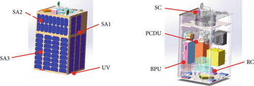
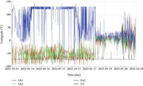
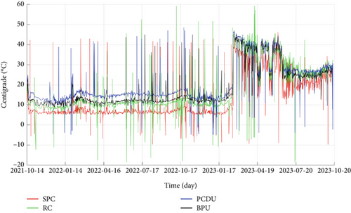
The TCS has also demonstrated robust performance, as evidenced by the temperature variations of key onboard equipment depicted in Figure 10. For instance, some surface temperature measure points, including the Solar Array 1 (SA1), Solar Array 2 (SA2), SA3, and UHF/VHF antenna (UV), are selected. The internal temperature measurement points, including SC, RC, power control and distribution unit (PCDU), and BPU, are also considered. The installation positions of the above equipment are shown in Figure 10a, and the corresponding temperatures are shown in Figure 10b,c. From Figure 10b,c, it can be observed that a sudden change in temperature occurred at the end of February in 2023. As mentioned in the above paragraph, at that time, a sudden fault of ADCS was encountered by SSS-1, and it could not maintain its sun-pointing attitude. Thus, the temperature distribution of the SSS-1 sharply changed after that time. Due to the relatively large design margin of the TCS design, in the 2-year period, the temperatures of these devices remained within the acceptable range. It indicates that the TCS has effectively regulated the satellite’s internal temperature, thus ensuring the proper functioning of all onboard systems.
In summary, the SSS-1 satellite’s platform has remained healthy and operational due to the reliable performance of its EPS and TCS. All the platform subsystems have played a crucial role in maintaining the satellite’s stability and functionality, contributing to the successful execution of its designated space experiments and missions. The normal operation of these subsystems underscores the robustness and efficiency of the educational satellite’s design and engineering.
4. Fault Analysis and Handling Strategy
During its operational period, SSS-1 encountered specific space-related challenges, such as a SEU and a subsystem failure of the ADCS. This section details the analysis of these faults and the strategies employed to manage them.
4.1. SEU During In-Orbit Operation
On September 5, 2022, a SEU disrupted the synchronization of SSS-1’s internal clock, resulting in internal second register bit shift. A detailed analysis of the SSS-1’s telemetry data revealed that the SEU had triggered a temporal leap, propelling the on-board satellite time of SSS-1 changed from September 5, 2022, forward to December 6, 2026. During the incident, SSS-1 was operating in the manual mode, and it would preclude its automatic memory recovery. So that, this sudden change was recorded by the telemetry data. Upon recognizing the anomaly as an SEU, the ground crews of SSS-1 in Beijing executed the manual GPS-time-correction command and the OBDH reset command. These commands successfully reset the SSS-1’s memory and thus restored the on-board satellite time of SSS-1, thereby safeguarding its operational efficacy.
Further scrutiny of the SSS-1’s telemetry data and space-weather recordings suggest a compelling link between this SEU event and heightened solar activity. Figure 11 presents the Kp index and Ap index [22]. Both these two parameters serve as key indicators of global geomagnetic storm intensity. The Kp index gauges the strength of geomagnetic disturbances across the planet, reflecting the Earth’s fluctuating magnetic field [23], and the Ap index provides a daily mean assessment of global geomagnetic perturbation levels [24]. Notably, Figure 11 reveals a conspicuous spike in both the Kp and Ap indices between September 4 and September 5, 2022, signaling an elevated state of solar activity during this period.
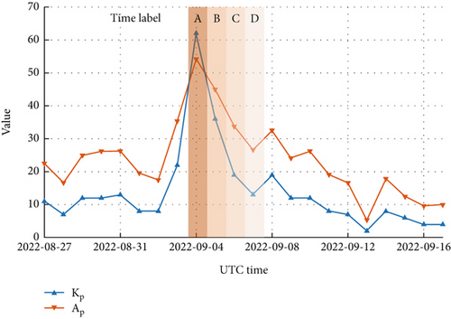
Besides, complementary to this analysis, the telemetry of the SSS-1 in orbit time of OBDH and UTC are shown in Table 4, with corresponding time labels aligning with Markers A to D in Figure 11. A striking observation from Table 4 is the abrupt divergence between the satellite’s in-orbit time and the standard UTC. It occurred between entry interval between September 4, 2022, at 22:14:47 to September 5, 2022, at 09:50:00. Moreover, the time differential recorded between September 5, 2022, at 09:50:00 and September 6, 2022, at 09:30:00 amounted to exactly 134,217,728 s—a value precisely equating to 2 raised to the 27th power. This numeric congruence bolsters the inference that the SSS-1 encountered an SEU, presumably instigated by a high-energy particle interaction.
| Time label | UTC | In-orbit satellite time | Difference (s) |
|---|---|---|---|
| A | 2022-09-04, 22:14:47 | 2022-09-04, 22:14:47 | 0 |
| B | 2022-09-05, 09:50:00 | 2026-12-06, 20:32:08 | 134,217,728 |
| C | 2022-09-06, 09:30:00 | 2026-12-07, 20:12:08 | 134,217,728 |
| D | 2022-09-07, 09:15:24 | 2022-09-07, 09:15:24 | 0 |
Collectively, these handling findings of SEU underscore the need for enhanced vigilance and mitigation strategies in response to solar-induced SEUs. Future satellite designs and operational protocols should incorporate radiation protection countermeasures and reduce excessive manual manipulation to fortify systems against such transient SEU disruptions.
4.2. ADCS Fault Encountered During In-Orbit Operation
The ADCS of SSS-1 aims to determine the satellite’s attitude by integrating information from various sensors and to use actuators to control the attitude according to the control objectives, ensuring the satellite’s pointing requirements and assisting the payload in completing its mission [25].
The ADCS sensor configuration of SSS-1 includes two sun sensors (with thermal backup) and two gyroscopes (with cold backup). The actuators consist of three magnetorquers (X, Y, and Z magnetic rods) and three reaction wheels. These components are managed by the attitude control computer (ACU). During the in-orbit operation of the SSS-1 satellite, the attitude control subsystem primarily operates in four modes: sun-acquisition mode (SAM), SPM, earth-pointing mode (EPM), and standby mode (SBM). Table 5 outlines the basic details of each mode and the operational equipment of each mode.
| Operation mode | Operational equipment | Main function |
|---|---|---|
| SBM | ACU | Stop all actuators and sensors to ensure satellite safety |
| SAM | ACU, sun sensors, gyroscopes, magnetorquers | Damp out angular velocity and start searching for the sun by rotating pitch and roll axes |
| SPM | ACU, sun sensors, gyroscopes, magnetorquers, reaction wheels | Point to the sun to ensure sufficient power supply |
| EPM | Point to the earth to carry out remote-sensing tasks |
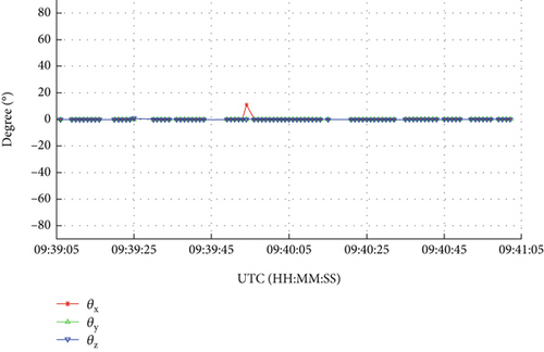
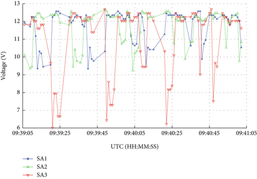
The first ADCS failure was encountered on February 24, 2023, when SSS-1 experienced an abnormal increase in angular velocity. This issue was first detected through the voltage telemetry of the solar arrays from the EPS. At that time, SSS-1 was in SPM, and its body axes should have been aligned with the SPM axes. The SPM axes are defined with the Y-axis pointing to the sun and the Z-axis in the plane containing both the sun vector and the earth vector. Figure 12 clearly shows that the attitude angle between the body axes and the standard SPM axes is close to zero. Besides, according to the design specifications, the sun-pointing panel (+Y panel) and the +X and −X panel panels are covered by the body mounted solar arrays. Given this alignment, if the +Y panel is pointing at sun, then the output power of SA3 should be stable, with the electric output of SA1 and SA2 should be close to zero. However, the telemetry data in Figure 13 show significant voltage variations in the solar arrays. For instance, there is a noticeable voltage change in SA3 from 6 to around 12 V, with a fluctuation period of about 28 s. This suggests that SSS-1 is rotating at an alarming speed of nearly 12.86°/s in space, raising serious concerns about the effectiveness of the ADCS.
4.3. ADCS Fault Analysis and the Response
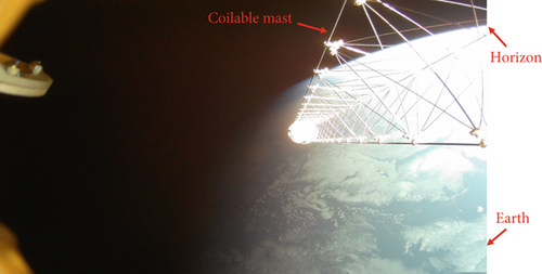
Aside from the ADCS data, the SC photos can also be used to verify the attitude of SSS-1. Therefore, a photo-taking command was uploaded to the SSS-1 on February 26, 2023. The photo, decoded in March 2023, is shown in Figure 14. Given that the SSS-1 is in SSO with the local time of the descending node being 18:00, when the SSS-1 is in SPM, if the ADCS is functioning correctly, the coilable mast should point toward the zenith direction. However, despite telemetry data indicating an attitude angle close to zero, with the occurrence of the earth and horizon, the photo evidently revealed that SSS-1 was not aligned with the standard SPM attitude. Additionally, the fluctuating voltages of the solar arrays confirmed that the ADCS was malfunctioning, meaning that the SSS-1 would rotate in space. After analyzing the telemetry data and carrying out ground experiments, the fault reason is attributed to a broken fiber gyroscope, which would transmit erroneous gyroscope data to the ACU. This situation prevented the SSS-1 from accurately determining its attitude and led to incorrect attitude maneuvers.
The abovementioned faulty rotation status of SSS-1 not only reduced power generation from the EPS but also resulted in significant power consumption, as the actuators were constantly in operation mode. To address this critical situation, the SSS-1 team initially attempted to activate the cold-backup mechanical gyroscope to replace the broken fiber gyroscope. However, possibly due to prolonged standby and lack of power supply, it did not function correctly even after sending multiple commands. Other attempts, such as switching SSS-1 into SAM and then recovering it to normal mode, also failed. Although the rotation speed sometimes slowed down in SAM, once the satellite switched back to SPM, the broken fiber gyroscopes consistently provided incorrect data to the ADCS computer, causing the satellite to rotate again.
Finally, the ADCS was switched to SBM in April, shutting down all equipment except the ADCS computer. This mode reduced energy consumption and prevented attitude anomalies caused by incorrect actuation of the attitude subsystem. By leveraging the coilable mast, the attitude of SSS-1 was successfully stabilized in about 1 month. This stabilization was confirmed through evaluations of the EPS recharge status, SC photos, and the TT&C status.
4.4. Effectiveness of ADCS Handling Strategies
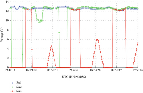
To evaluate the effectiveness of our handling strategies, we firstly analyzed the EPS recharge status. Figure 15 is the voltage telemetry data of the three solar arrays on April 24, 2023. The voltage fluctuation period of SA3 was about 236 s, indicating a rotation speed of approximately 1.53°/s, suggesting near-stabilization of SSS-1’s attitude.
Furthermore, we analyzed SC images taken on May 2, 2023, as shown in Figure 16. Compared with Figure 14, where the earth occupies a considerable proportion, the earth’s horizon in Figure 16 is now positioned at the exact corner of the photo. This improvement indicates a significant stabilization of SSS-1’s attitude since April 2023. The visible earth’s horizon with a blue shimmer in the lower left corner serves as a reliable reference point for further attitude determination.
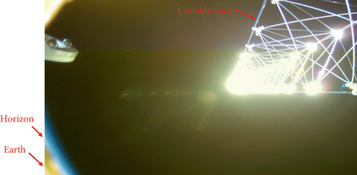
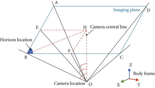
Since the camera is installed pointing to the +Z-axis of the SSS-1, we conclude that the +Z-axis of the SSS-1 body frame forms an angle of approximately 36.1° with the zenith direction. In other words, if we define the vehicle velocity local horizontal (VVLH) coordinate system, in which the +X-axis points in the direction of the SSS-1’s velocity vector and the +Z-axis points from the SSS-1 directly toward the center of the earth, the angle between the +Z-axis of the SSS-1 body frame and the +Z-axis of the SSS-1 VVLH is approximately 36.1°. This result demonstrates that the ADCS failure was largely resolved.
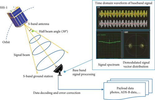
Additionally, the S-band data transmission results also show that the attitude of SSS-1 is becoming stable since the ADCS is turned into the SBM. SSS-1 has two S-band antennas, and each of them has a half beam angle of about 30°, which requires the ground station to lie within a conical region for stable data transmission. Figure 18 shows the diagram of data transmission and decoding of SSS-1. In our S-band ground station, the base band signal processing unit has the ability to generate the signal spectrum and the demodulated signal vector distribution, allowing us to extract the signal-to-noise ratio (SNR) and determine the optimal signal quality and timing. As the S-band antenna is installed at the bottom of the SSS-1 and is pointing toward the Z-axis of the body frame, once the SNR is relatively high, it can be deduced that the S-band antenna is pointing toward the ground station, which can be used to statistically infer the attitude of SSS-1.
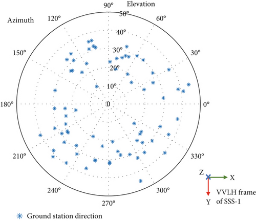
In the early period of the ADCS fault, S-band data transmission could hardly carry out due to the unstable base band frequency locking, and after SSS-1 is set into the SBM, the data transmission has gradually recovered since May 2024. Using orbit simulation, we obtained the ground station’s azimuth and elevation angles relative to the position of SSS-1 at the times of best signal quality for successful data transmissions. From May to August, 73 transmissions were successfully carried out, and the corresponding azimuth and elevation angles are shown in Figure 19. The results demonstrate that data transmissions consistently succeeded when ground station elevations were around 20°–40°. This also confirms that the angle between the +Z-axis of the SSS-1 body frame and the +Z-axis of the SSS-1 VVLH is around 30°.
5. Conclusion
This paper provides an in-depth description of the SSS-1 satellite mission and in-orbit operation, focusing on its payload performance and fault analysis. Beginning by the satellite’s design and subsystem integration, this paper discusses the SSS-1’s in-orbit operation results, which includes space experiments of coilable mast, remote sensing, electrical propulsion tests, and ADS-B test. These experiments demonstrate the robustness and functionality of all subsystems and payloads during different operational phases. Despite experiencing SEU and ADCS fault in 2023, the cause identification of these problems was accomplished quickly, and the corresponding handle strategies were taken. For the ADCS fault, appropriate steps were taken to mitigate rotation and redetermined attitude through alternative method, which ensured minimal disruption to the mission.
SSS-1 is the first educational small satellite which is systematically designed by Beihang University and has been operated for over 2 years. Above testing results underscore the effectiveness of SSS-1’s platform system design, its payloads design, as well as the satellite ground control network. The findings and experiment results could provide useful insights for the future development of educational small satellite missions, with the successful implementation and in-orbit testing of SSS-1 setting a strong example for international educational satellite programs.
Conflicts of Interest
The authors declare no conflicts of interest.
Funding
This work was funded by the Student Small Satellite (SSS) program of the Asia-Pacific Space Cooperation Organization (APSCO) and the Outstanding Research Project of Shen Yuan Honors College, BUAA (Grant Number 230123205).
Acknowledgments
This work was supported by the Student Small Satellite (SSS) program of the Asia-Pacific Space Cooperation Organization (APSCO) and the Outstanding Research Project of Shen Yuan Honors College, BUAA (Grant Number 230123205). The authors also wish to thank the complete SSS-1 team.
Open Research
Data Availability Statement
The data that support the findings of this study are available from the corresponding author upon reasonable request.


