A Battery-Based Energy Management Approach for Weak Microgrid System
Abstract
The conversion loss is the significant challenge due to the usage of multiple converters at different stages of a power distribution system. These stages include distribution of energy, energy storage, grid integration, and energy demand management. The conversion losses at each stage adversely impacts the performance of the power system, especially toward energy conservation if efforts are made toward it. To address this, a novel microgrid (MG) energy management scheme is introduced to mitigate conversion losses in distribution systems specifically under weak MG environment. This scheme employs a sophisticated control algorithm that assesses the potency of power available on the DC side before initiation of the conversion process. Conversion is executed only when available power meets the specific level. Otherwise, it is diverted and stored in a battery bank to prevent high losses. In this scenario, the AC loads are supplied by the utility grid while solar and battery bank catered the DC loads. The conversion process is selectively activated, prioritizing its use during indispensable circumstances. By optimizing conversion losses, this work reduces the energy prices by 1.95%. The proposed scheme guarantees economical deployment and affordability because of its effectiveness in a weak MG environment, thus promoting sustainable energy resources.
1. Introduction
Energy is essential to many facets of our everyday lives and the advancement of societies. It is frequently referred to as the lifeblood of modern civilization. This is especially important in the context of the 21st century because of the problems we have, such as resource depletion and climate change. Scientific research and technological development are greatly aided by energy [1]. Recently, the use of fossil fuels such as coal and oil has been the main method of meeting the world’s energy needs. However, the release of greenhouse gases (GHGs) from these sources has a negative impact on the ecosystem. The greatest sustainability challenge facing humanity today is the GHG emissions and the global climate change. The global electricity generation by fossil fuels is still higher in 2024. It is anticipated that fossil fuel stocks may run out soon. In order to fulfill the growing energy demand, the trend toward the usage of renewable energy sources (RES) is enhancing. The RES such as solar, wind, hydropower, and geothermal are very attractive in the modern era as they are environment friendly [2]. Majority of the countries are working prominently on solar energy especially on photovoltaic (PV) systems [3].
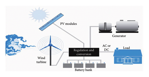
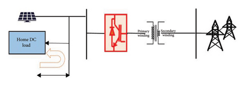
The energy produced by PV systems is in the form of direct current (DC). Figure 1 shows the hybrid solar–wind power generation project for a house wherein the major point of concern is the regulation and conversion block. The use of DC appliances has been steadily rising in the modern era [5]. The DC equipment are often connected to the alternating current bus as independent DC supply systems are not available at the customer’s location. Multiple conversions are made to meet the needs of different DC load requirements. The power system network is contaminating severely by the converters’ conversion losses and harmonics. The average power loss from these conversion procedures is between 10% and 30% [6]. Thus, the phenomenon of conversion loss represents one of the major obstacles in the current power distribution system.
The use of DC supply in customer premises has evolved the concept of microgrid (MG) [4]. The MGs are localized energy systems that can operate independently or in conjunction with the main power grid, allowing for efficient integration of low-power RES such as PV systems. This development addresses the changing landscape of energy generation and distribution, offering more flexibility and sustainability in energy management [7]. However, the PV integration imparts certain limitations due to its intermittent nature. Ultimately, their coordination with the MG is a challenging task for efficient operation. The notable challenges are voltage instability, load discrepancy, frequency variation, and power quality reduction [8].
The integration of a battery energy storage system (BESS) is a promising solution to avoid aforementioned challenges, and it improves the power quality and enables ancillary services [9]. Furthermore, an ML-based virtual inertia (VI) synthesis is proposed by authors in [10] to improve grid frequency stability in solar PV systems. When BESS is connected to a traditional AC bus, considerable conversion losses occur. The optimized operation in the DC bus contributes to more advantageous efficiency and effectiveness of the power storage device in MG surroundings [11, 12]. The PV-based MGs pose a number of technical difficulties because of their erratic nature. If there is a power shortage, the power conversion is still required even with the AC/DC hybrid MG [12–14].
The researchers have worked on different strategies regarding energy management systems (EMS) and address many problems. These include managing peak demand, arranging and prioritizing loads, installing load-shedding techniques, deploying energy sources as efficiently as possible, and effectively managing energy storage. Thus, enhancing the overall dependability and efficiency of energy systems is the major goal of these methods [15, 16]. In [17, 18], the power availability of the renewable energy system is evaluated in relation to the load needed to satisfy the demand. The goal of battery management strategies is to minimize costs by operating at minimal tariff and manage peak demand for affordable energy costs. Similarly, batteries used in stand-alone MG systems are only used when RES is unavailable or the power supply is erratic [19–21].
A comparative analysis has been tabulated in Table 1 to highlight the uniqueness of the different works. This includes the efficient control of BESS in order to maximize the efficiency and manage the weak MG.
It has been observed from the empirical literature review that the conversion processes are controlled by varying the thresholds and by controlling different situations. Nevertheless, during the AC/DC power conversion procedure, two crucial eventualities have not been handled. Firstly, the solar power will be exported when there is enough power through the interlinking converter. However, if insufficient solar PV power is available, the converters are forced to convert it, which produces greater losses, consequently, enhancing the conversion losses. Secondly, when there is less solar power and low demand of DC load, the electricity is imported from the utility. This scenario also produces conversion losses.
The goal of the proposed research is to reduce the conversion losses by managing the energy usage efficiently especially under a weak MG environment. It will be achieved by designing a novel MG energy management scheme to lessen the conversion losses in distribution systems specifically under a weak MG environment. This scheme employs a sophisticated control algorithm that assesses the potency of power available on the DC side before initiation of the conversion process.
2. Modeling of the System
2.1. EMS
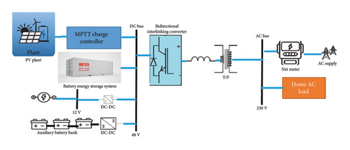
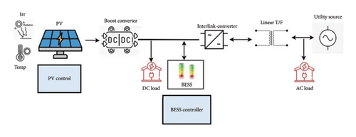
The goal of this study is to reduce the conversion losses by designing a hybrid AC/DC MG powered by RES and a battery-based EMS. In this work, the efficiency of a 1-kW solar PV system in both grid-connected and stand-alone modes is tested in a weak MG environment. The proposed battery-based EMS configuration is depicted in Figure 2. It incorporates low-voltage systems with RES such as PV systems and batteries.
2.2. PV Panel Arrangements
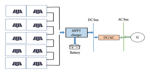
For the suggested electrical power system, a one-diode solar energy configuration was selected because of its effectiveness in striking a balance between accuracy and usability. Ten numbers of 100 W PV panels (Model No. DSP100) are incorporated into the system. The configuration consists of five parallel groups, each of which has two panels connected in series to produce a 48-V terminal voltage, as illustrated in Figure 3.
2.3. Bidirectional DC Converter
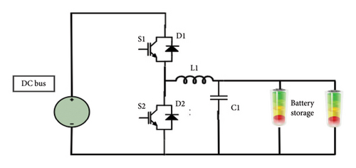
A 48-V level is selected in a DC MG system to reduce conversion steps and effectively supply energy. Bidirectional DC converters are used to connect energy storage systems (ESSs) to the DC bus and solar panels to provide power to the DC network, as shown in Figure 4. These converters enable efficient, dependable, and dynamic system performance by operating in multiple modes while stabilizing variations in DC voltage.
2.3.1. Scenario-I (Charging)
In the buck mode during battery charging, the converter steps down the input voltage using switch S1 and diode D2. High-frequency switching of Switch S1 permits energy to flow from the inductor to the battery. By ensuring proper current flow, diode D2 stops backflow to the input source. This process effectively regulates voltage and current while controlling battery charging.
2.3.2. Scenario-II (Discharging)
During power outages, the converter runs in the boost mode, using Switch S2 and Diode D1 to increase battery voltage to power the load in order to fulfill DC array bus demand. Switch S2 alternates at high frequency, transferring energy from the battery through the inductor to the load, while Diode D1 prevents backflow.
2.3.3. Scenario-III (Standby)
2.4. Configuration of MG Converter
A bidirectional interlinking converter controls the transfer of power between the AC and DC buses in the AC/DC MG, as depicted in Figure 5. The IGBT switches use sinusoidal pulse width modulation (SPWM), which is only active during inversion, to switch gates at a frequency of 10 kHz. Solid-state switches SA (utility connect) and SB (converter connect) to regulate the flow of power. Despite different voltage levels such as 400, 326, 220, and 120 V, the DC bus voltage is kept at 48 V, which is perfect for low-energy home needs.
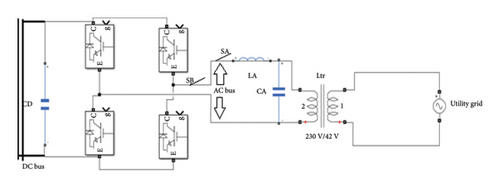
The solar maximum power tracking controller and BESS converters work together to stabilize the DC array voltage. Solar energy surpluses are sent to the grid to be stored. The battery charges while operating autonomously in order to maintain energy balance and voltage stability.
3. Proposed Methodology
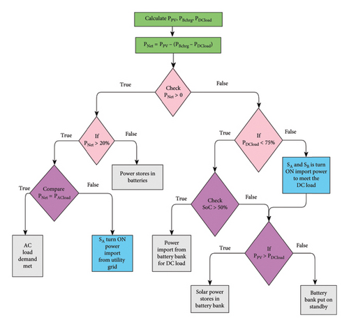
Figure 6 shows the proposed algorithm of the battery-based EMS. The transformer connected to the circuit exhibits low efficiency when supplied with less than 20% of its rated value; thus, the converter threshold limit is set at 20%. When the converter is loaded below this threshold, its performance can be decreased by 52.3%. It only reaches a significant level when it is loaded to over 20%.
- 1.
Firstly, battery power, DC load requirements, and energy at the solar array terminals are measured. A 1-kW of PV panels can supply half of the AC loads and most of the DC side loads installed.
- 2.
After determining the power needed for battery charging (PB chrg) using MPPT and the DC side load requirement (PDC Load), the net PV power (PNet) that is left over is computed. PNet is calculated from equation (2). If the PNet exceeds 20% of the rated value, then Switch SB turns ON and uses the inverter mode. If the condition is satisfied, it transmits power to the loads linked to the utility terminal. Otherwise, the available power is saved in the auxiliary battery.
- 3.
If the PNet is negative (< 0), it means that PPV is insufficient to meet the DC side power requirement. For this scenario, the energy demand is smaller than 75% of the rating. In this case, examine the SoC of the battery; if it is > 50%, then fulfill the DC requirement.
- 4.
If SoC is < 50%, then batteries will be charges if and only if solar power is available. Otherwise, they wait for the solar power to become available.
- 5.
Finally, the accessible energy is then supplied to the utility bus terminal after the PNet is checked to see if it equals AC load. The energy could be surplus or lacking if the condition is not met. The SA is switched ON to transmit and receive electricity during these times. The Switches SA and SB are typically in the OFF position.
In the MG EMS system, weak power prevails on multiple occasions. The following three cases illustrate this phenomenon.
3.1. Case-I
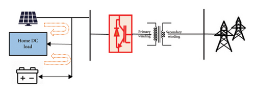
Low solar power output periods (7 a.m.-8 a.m. and 4 p.m.-5:00 p.m.) typically result in the loads being supplied from the grid and PV energy being left idle. During these times, power conversion is used to supply the DC loads linked to the MG system’s DC bay terminal from the utility. The proposed plan uses an auxiliary battery to support the available solar power to feed the DC loads, as shown in Figure 7. The utility feeds the AC loads. Implementing this kind of energy management reduces the conversion process.
3.2. Case-II
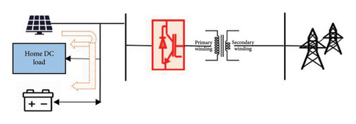
The solar PV system produces power between 8:00 a.m. and 9:00 a.m. and 2:00 p.m. and 4:00 p.m., which is barely sufficient to supply DC side loads. After that, very little power is left. This scenario has not been covered in the literature that is currently available. No appropriate plan has been found in any literature to address the intermittent solar power that occurs throughout the day. Such weak power is moved to the AC side in conventional schemes via the inverter. However, if the inverters are not loaded to their rated value, they perform poorly.
As a result, the weak power is wasted during the conversion process and cannot be converted efficiently. A control strategy has been developed to address this phenomenon, storing the weak power in an auxiliary battery. The setup is shown in Figure 8. The two benefits of this strategy are that we charge our auxiliary backup storage from DC source and that weak power is preserved.
3.3. Case-III
Late night (10:00 p.m.–5:00 a.m.) is when the DC side load is least needed. There will be greater losses in the transformer and converter components if power is imported from the grid to meet low energy demand than would occur otherwise. The storage backup is assigned to supply the DC loads in order to solve this problem. In addition, the battery’s SoC is routinely assessed to prevent deep discharge setup, as shown in Figure 9. In the MG DC network, weak power is prevalent during the aforementioned time. Power imports or exports at such a time will not be successful.
Therefore, the threshold value and control strategy have been developed so that the auxiliary battery bank can efficiently handle and store the weak power. Power-saving options are therefore enhanced.
4. Results
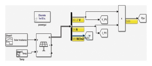
A simulation-based model has been modeled in MATLAB to analyze and test the proposed approach. For this, we have divided the project into two sections: the utility system and solar generation using an MPPT controller and batteries for energy storage. The RES consists of 10 100 W solar panels arranged in five parallel configurations having two panels in a series. The proposed model is shown in Figure 10.
The energy management module was simulated with varying solar radiation, with the goal of determining the best load management techniques. For this purpose, data on temperature and solar radiation were acquired from DNV’s Atlas 100 MW Solar Plant near Multan, Punjab, Pakistan. The solar irradiance is plotted in Figure 11(a), and the Simulink model is shown in Figure 11(b).

The simulations are performed in the MATLAB Simulink environment, and results are analyzed by Scope and Data Inspector. Over 24 h, a thorough simulation was carried out to examine how DC power is distributed in homes using PV systems while considering temperature and irradiance variations. The main goal is to observe the system behavior under different environmental conditions, such as fluctuating temperatures and sunlight levels. These elements have a significant impact on the PV system performance, influencing both the capacity to generate power and overall efficiency.
Different scenarios were tested and observed different results on different temperatures and solar irradiance, as shown in Table 2. These variations affect the PV system’s performance during the day, as well as it affects the distribution and availability of DC PV power to the residential loads.
| Hours | Ambient temp (C) | Irradiation (W\m2) | PV DC output (W) |
|---|---|---|---|
| 0 | 22.900 | 0 | 0 |
| 1 | 21.600 | 0 | 0 |
| 2 | 21.320 | 0 | 0 |
| 3 | 20.890 | 0 | 0 |
| 4 | 20.500 | 0 | 0 |
| 5 | 20.200 | 0 | 0 |
| 6 | 22.322 | 70 | 78.1 |
| 7 | 26.430 | 176.49 | 158 |
| 8 | 28.700 | 462.71 | 451 |
| 9 | 31.654 | 749.33 | 740 |
| 10 | 33.000 | 918.13 | 910 |
| 11 | 34.450 | 1015.38 | 990 |
| 12 | 35.700 | 975.04 | 970 |
| 13 | 36.400 | 830.18 | 936 |
| 14 | 35.720 | 624.96 | 766 |
| 15 | 34.500 | 381.41 | 498 |
| 16 | 33.780 | 144.65 | 170 |
| 17 | 31.100 | 85 | 99 |
| 18 | 28.765 | 0 | 0 |
| 19 | 26.700 | 0 | 0 |
| 20 | 25.730 | 0 | 0 |
| 21 | 24.900 | 0 | 0 |
| 22 | 24.200 | 0 | 0 |
| 23 | 22.660 | 0 | 0 |
4.1. Losses in Storage Bank
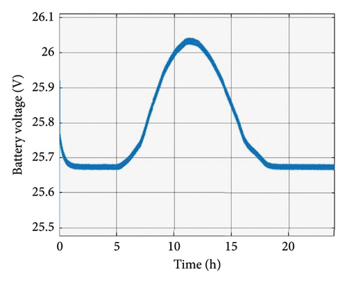
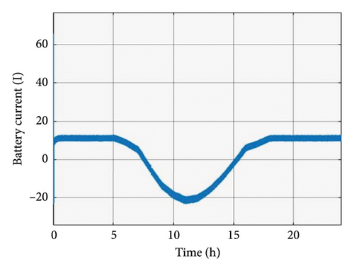
The PV output is supplied to the DC bus which is connected to a group of four 12 V batteries to create 48 V connection. The battery’s performance was simulated, and the results of the simulation were thoroughly examined. Battery current and voltage are shown in Figure 12. The findings demonstrated that battery charging current and voltage remain constant in the absence of PV power but change in the presence of PV power. The battery bank charging is shown by the negative curve.
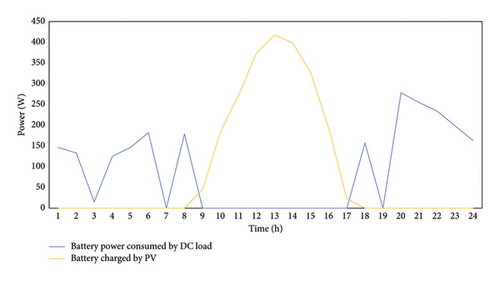
In this proposed EMS scheme, the MG DC bus is connected to the solar panel, DC loads, and batteries. The DC MG primary DC bus voltage is intended to run at 48 V. A DC-DC converter with bidirectional operation is utilized to regulate charge. In this way, there is much less conversion which is advantageous for the cause. The battery power consumed by the DC load and battery charged by PV is shown in Figure 13 and tabulated in Table 3.
| Hours | DC load consume battery power | Battery charged by DC (W) |
|---|---|---|
| 0 | 146.2 | 0 |
| 1 | 133.1 | 0 |
| 2 | 14.99 | 0 |
| 3 | 124.98 | 0 |
| 4 | 146.01 | 0 |
| 5 | 181.78 | 0 |
| 6 | 0 | 0 |
| 7 | 179.05 | 0 |
| 8 | 0 | 44.93 |
| 9 | 0 | 184.44 |
| 10 | 0 | 272.12 |
| 11 | 0 | 374.89 |
| 12 | 0 | 416.99 |
| 13 | 0 | 398.37 |
| 14 | 0 | 325.92 |
| 15 | 0 | 191.65 |
| 16 | 0 | 21.99 |
| 17 | 157.11 | 0 |
| 18 | 0 | 0 |
| 19 | 278.2 | 0 |
| 20 | 254.55 | 0 |
| 21 | 233.99 | 0 |
| 22 | 198.17 | 0 |
| 23 | 162.56 | 0 |
4.2. Utility Consumption
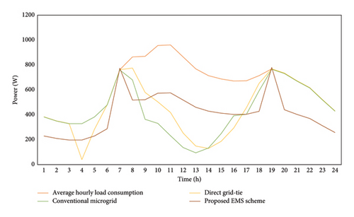
In this work, the three different energy management schemes were compared. It includes direct grid-tie, conventional MG, and the proposed one. The data which were gathered hourly for a day show notable variations in each scheme efficiency.
The usage of utility in the direct grid-tie scheme was higher than anticipated, thus resulting in inefficient energy use. It is possible that a considerable amount of energy was extracted from the grid rather than produced by the system itself. This leads to a poor system. The energy consumption for the conventional MG system was marginally lower than that of the direct grid-tie system. In this scenario, the conventional MG was less dependent on grid power and relatively efficient in controlling energy requirements. However, the proposed EMS scheme demonstrates superior performance. It continuously shows the lowest utility consumption in comparison to others, as shown in Figure 14. This reduction in utility consumption provides an economical and sustainable approach to energy management.
4.3. Conversion Loss Analysis
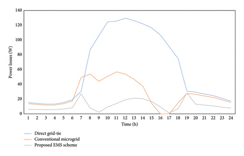
The conversion loss analysis in three different energy management schemes, such as direct grid-tie, conventional MG, and proposed EMS scheme, is also performed. This assessment was carried out for a full day with hourly measurements of the losses.
Over the course of the day, the direct grid-tie scheme consistently loose money, showing a typically inefficient performance. Due to the increasing demand or system strain, the losses marginally increased during peak hours, as shown in Figure 15. It would appear from this that the system was not set up to effectively manage high loads. In conventional MG, the inefficiencies throughout the day are indicated by the shifting losses. The two different peaks indicate increased system strain or malfunction. The system’s inability to sustain an optimal performance during these peaks resulted in higher losses. However, the proposed scheme significantly lowers losses, especially during periods of high demand, as tabulated in Table 4. Consequently, this scheme surpasses the previous techniques by providing a highly effective solution by lessening the conversion losses.
| Hours | Direct grid-tie (W) | Conventional MG (W) | Proposed scheme (W) |
|---|---|---|---|
| 0 | 15.37 | 13.83 | 6.17 |
| 1 | 14.03 | 12.62 | 5.93 |
| 2 | 13.2 | 11.87 | 5.77 |
| 3 | 13.2 | 11.87 | 5.77 |
| 4 | 15.37 | 13.83 | 6.56 |
| 5 | 19.21 | 17.29 | 8.31 |
| 6 | 30.48 | 49.26 | 27.2 |
| 7 | 86.38 | 53.87 | 8.19 |
| 8 | 105.76 | 44.079 | 2.15 |
| 9 | 124.31 | 50.8 | 9.33 |
| 10 | 125.55 | 56.8 | 13.98 |
| 11 | 129.46 | 54.04 | 19.1 |
| 12 | 126.16 | 46.84 | 21.33 |
| 13 | 121.89 | 37.46 | 20.49 |
| 14 | 116.53 | 14.18 | 16.67 |
| 15 | 106.63 | 0 | 9.33 |
| 16 | 90.95 | 0 | 1 |
| 17 | 74.86 | 14.94 | 7.09 |
| 18 | 30.73 | 27.66 | 28.22 |
| 19 | 29.39 | 26.45 | 13.09 |
| 20 | 26.83 | 24.2 | 11.88 |
| 21 | 24.72 | 22.25 | 10.87 |
| 22 | 20.88 | 18.78 | 8.98 |
| 23 | 17.22 | 15.495 | 7.88 |
| Total | 1479.11 | 638.414 | 275.29 |
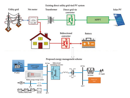
The proposed EMS scheme guarantees optimal solar power utilization and efficient battery management. The comparison between the existing direct utility grid-tie PV system and the proposed EMS is shown in Figure 16. The addition of a bidirectional DC-DC converter permits precise control over battery charging and discharging, minimizing losses and improving the overall system performance. An MPPT charge controller maximizes the conversion of solar energy, particularly in low-sunlight situations.
5. Discussion
The primary objective in renewable energy resources is to reduce the power conversion losses and to lower the electricity costs. The power conversion efficiency has the direct impact on the overall performance of renewable energy systems especially in a weak MG environment. The proposed energy management scheme optimizes power usage and reduces the unnecessary conversions. Thus, it offers an economical and efficient solution than the prior model. It uses an innovative control algorithm that evaluates the availability of the PV power prior to conversion. Conversion is executed only when the available power meets the specific level. Otherwise, it is diverted and stored in a battery bank to prevent high losses. This method optimizes battery use and increases system efficiency. With the addition of centralized DC bus, bidirectional interlinking converter and multistage DC-DC converters in the proposed scheme enhance the power flow management, ultimately, providing greater control and flexibility.
This scheme is beneficial under the weak MG environment by reducing the conversion losses. The reduction in conversion losses provides financial paybacks while using renewable energy resources, that is, PV system. This prototype work provides a sustainable, scalable energy solution that make it possible for renewable technology to be used at a large scale. It is a good choice for both residential and business applications since it provides more cost-saving options in time-of-use tariff systems.
6. Conclusion
There occur conversion losses in a traditional MG system irrespective of the PV power production. It adversely impacts the performance of the traditional MG specially during feeble PV power production. In this study, a sophisticated scheme is introduced to lessen the conversion losses in the weak MG environment. This scheme not only reduces the conversion losses by 1.95% but further enhances the efficiency of battery bank by 9%–11%. The conversion losses are reducing by two ways. During the day time, if there is sufficient power, then it fulfills both AC and DC load requirement, and during feeble power, the PV power are stored in the battery bank and fulfill only DC load requirement. During night time, if the battery bank power meets the DC and AC load, then the power is used from the battery bank instead of importing from utility. However, in case of low battery power, the utility fulfills the AC load and the battery bank just supplies the DC load.
By using an automatic centralized MG controller, conversion losses have been reduced and energy has been managed efficiently. A comparative study has been carried out to demonstrate the advantages of the proposed scheme over traditional technologies. The benefits that are obtained include the efficient control and utilization of weak power during off-peak hours or low radiation. Effective power management during peak and off-peak hours reduced conversion losses and enhanced battery support energy management that reduces conversion steps and boosts battery energy efficiency. Demand response and the intelligent management of renewable resources all contribute to increased energy efficiency. The energy consumption of the MG environment has been optimized, and electricity costs have significantly dropped.
Conflicts of Interest
The authors declare no conflicts of interest.
Funding
This work received no funding.
Open Research
Data Availability Statement
The data that support the findings of this study are available from the corresponding author upon reasonable request.


