

A Low-Cost Microcontroller Implementation of Fuzzy Controller for Renewable Energy Converters
Abstract
Microcontrollers (μCs) are extremely useful in renewable energy (RE) converters, where numerous onboard control actions need to be executed at low cost. This paper focusses on a cost-effective implementation of a fuzzy controller (FC) for the regulation of converters that are normally employed in RE applications such as solar, wind, and tidal. The μC realization has been achieved through simplification of a dual-input FC (DFC) into a single-input FC (SFC) using the signed distance approach, followed by the piece-wise linear (PWL) simplification of SFC named as piece-wise-linear single input FC (PWL-SFC). Despite the elimination of the fuzzification, knowledge inference, and defuzzification stages, PWL-SFC exhibits a similar control performance to that of DFC. The proposed PWL-SFC is tested through modeling and simulation using the MATLAB Simulink platform and experimentally validated through a low-cost dsPIC μC. The results reveal that the proposed PWL-SFC requires negligible tuning effort and uses three orders of magnitude less computational power compared to DFC.
1. Introduction
Electricity generated from renewable energy (RE) sources such as wind, hydrogen, and solar is being widely promoted to protect the environment and reduce dependence on fossil fuels. RE sources, however, possess specific electrical characteristics that cause their output voltage to fluctuate due to load variations and changing weather conditions. These fluctuations can lead to inefficiencies and instability in power supply, if not properly managed. Therefore, to attain a regulated input/output voltage along with optimal power from a RE sources, a power converter with good dynamic control is indispensable [1].
The fuzzy controller (FC) is an ideal choice for RE converters due to its excellent dynamic response, robustness, high immunity to disturbances, and model independence, as it does not require detailed knowledge of the process or application [2]. A conventional dual-input FC (DFC) processes the control signal through multiple computational stages: fuzzification, rule base, inference, and defuzzification. These stages, particularly the rule base, significantly increase the computational burden, making it challenging to achieve a low-cost implementation. The rule structure of DFC is composed of (-if-then-else-) statements, digital processors are utilized to implement DFCs in power converters; for instance, digital signal processors (DSPs) [3], field-programmable gate arrays (FPGAs) [4, 5], and μCs [6, 7]. Although fast and accurate results are envisaged using FPGAs and DSPs, they increase the overall cost of the system. In contrary, μCs are more cost effective compared to FPGAs and DSPs but in order to implement a FC-based RE system using a low-cost μC, computational burden needs to be optimized.
Since, efficient and timely control responses are crucial for maintaining the stability and performance of RE systems, reduction in computation time without compromising the effectiveness of DFC is a prime requirement [8]. Accordingly, authors in [8–11] proposed the reduced form of DFC but realization was carried out using expensive processors; for instance, FPGA in [8, 10], while DSP in [9]. Another reduced version of FC was reported by authors in [11], but only simulation results were presented; hence, digital implementation is still questionable. Despite the simplification of the rule base from p2 to p (where p is the number of membership functions in DFC) in these works [8–11], various stages of FC are still incorporated. The simplified single-input FC (SFC) still needs to carry out fuzzification, rule inference, and defuzzification blocks; hence, the computational burden of the digital processor still exists.
It is deduced that various computation stages are the root cause of computation overload. Consequently, eradication of these stages without jeopardizing the control performance can address this problem. This paper therefore aims to simplify the DFC using the two approaches: signed distance approximation (SDA) and piece-wise linearization (PWL). The former deforms two fuzzy inputs into a single variable and later linearizes the inherent nonlinear control surface of DFC. The resulting controller is thereby named as PWL-SFC, and it does not involve any fuzzification, rule inference, and defuzzification stage. The apparent advantage of this simplification is the lesser degree of computational load. In a microcontroller (μC)-based implementation, both the DFC and SFC controller requires multiple operations, including membership function evaluation, rule-based inference, and defuzzification to compute the output. These steps involve multiple arithmetic computations and conditional checks, leading to higher execution times and increased resource usage. Conversely, the PWL approach directly maps the input to the output using predefined linear segments, which can be executed with fewer conditional checks (if-else statements) and arithmetic operations. This simplicity reduces the computational overhead by directly addressing the key metrics such as the HEX file size and RAM usage that determine the computational burden in μC-based implementations. These metrics directly reflect the resource efficiency and feasibility of implementation on low-cost μCs [12]. Therefore, the proposed FC is envisaged to be very effective for RE converters, where not only closed-loop control but other processes such as maximum powerpoint tracking (MPPT) are also executed by the μC. Rigorous simulations supported with experimental results have been presented to prove the effectiveness of the proposed PWL-SFC.
The organization of the paper begins with the mathematical modeling of the dc-dc converter, which is used to regulate the input/output voltage which is described in Section 2. In Section 3, the transformation from dual to single input of the conventional FC has been described, which serves as the basis of linearization of the fuzzy control surface. Section 4 presents the MATLAB simulation results of DFC, SFC, and the proposed PWL-SFC. The experimental validation of PWL-SFC through a low-cost μC is described in Section 5. Finally, conclusive findings and remarks are given in Section 6.
2. Mathematical Modeling of dc-dc Converter

3. Proposed PWL-SFC Schemes
3.1. Conversion From DFC to SFC
 |
The distance variable d represents the absolute distance of the parallel diagonal lines from DZ and λ is the slope of the line DZ.
The transformation mechanism from DFC to SFC is shown in Figure 2. The inputs to the FCs are (e = vref–vx) and its derivative (). The signal, vref, is the reference voltage, while vx could be an input (vpv) or output (vo) voltage. The scaling factors, K1 and K2, adjust the universe of discourse (UoD) of two fuzzy inputs, e and , respectively.

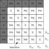
Since, the simplification is performed at the input side, the output variable Δu is unchanged. Due to the PI-type structure, the final output variable of both FCs is integrated to compute the control signal u. In contrast to p2 rule-base of DFC, only p rules need to be inferred in SFC. The resultant input–output membership functions of SFC are shown in Figure 3. The distance inputs, dN,2, dN,1, d0, dP,1, and dP,2, are denoted as the peak locations of membership functions DNM, DNS, DZ, DPS, and DPM, respectively. Table 2 shows the transformed rule table of SFC.

| Input, d | dN,2 | dN,1 | d0 | dP,1 | dP,2 |
|---|---|---|---|---|---|
| Output, ∆u | S‒2 | S‒1 | S0 | S1 | S2 |
Despite this simplification, fuzzification, rule inference, and defuzzification stages still need to be executed to calculate the Δu signal by SFC. However, with the help of linearization between two adjacent input membership functions, an equivalent PWL control surface can be constructed, which is discussed in Section 3.2.
3.2. Conversion From SFC to PWL-SFC
As can be seen from equation (11), the equations are only a function of peak locations of its membership functions. Thus, a PWL surface can be achieved by merely changing the peak values and, if required, can be further modified to achieve the optimal results. The formation of linearized control surface is shown with two supporting illustrations in Figures 4(a) and 4(b). The first illustration shows a linear line due to a constant slope throughout the UoD. The resulting surface is obtained for the evenly and 50% overlapped membership function for inputs and outputs, respectively.


A more complex case is shown in Figure 4(b), where the PWL surface is formed for the unequal spacing of membership functions. Moreover, two new membership functions are introduced for both inputs and outputs, denoted respectively by (DNB and DPB) and (S3 and S–3). Compared to the former case, the overlapping between the various membership functions is also uneven. This uneven overlap of membership functions results in multiple linear segments in the PWL surface, each characterized by distinct slopes and breakpoints. In this case, the seven linear segments are formed (see Figure 4(b)), increasing the number of if-statements executed by the μC. However, the computational burden still remains significantly lower than that of traditional DFC and SFC. For reference, a dsPIC30F μCtypically requires approximately 100–200 ns to execute a single if-statement, depending on the compiler optimization and instruction cycles. In contrast, the fuzzification, rule evaluation, and defuzzification steps in DFC and SFC require multiple conditional checks and arithmetic operations, taking considerably more processing time. These processes can range from several μs to tens of μs, depending on the complexity of the membership functions and the number of rules. Hence, even with a nonlinear PWL control surface, the proposed method’s computational load is much lighter due to its elimination of these stages, making it more efficient and feasible for real-time applications.
The proposed FC for a dc-dc Ćuk converter is depicted in Figure 5. The elimination of fuzzification, rule inference, and defuzzification step is expected to noticeably improve the computation time. Consequently, equation (11) can be implemented using any low-cost μC. For the case of DFC and SFC, both the shape of membership functions and rules must be stored in the digital processor. It should also be noted that PWL approximation not only speeds up the computation time but also reduces the memory space of the processor chip.

4. Simulation Results
To authenticate the efficacy of the proposed PWL idea, various simulations of DFC, SFC, and PWL-SFC are conducted. Figure 6 shows the block diagram of the simulation scheme. A nonideal switching model of the Ćuk converter is implemented in the MATLAB/Simulink platform. The following specifications for the converter are used: C1 = 10μF, C2 = 22μF, L1 = 160μH, and L2 = 360μH. The converter switching frequency is set to 50 kHz. The conduction losses of various components in the Ćuk converter are directly taken from their datasheets. As a test case, a solar PV system is considered for the implementation of the proposed controller. The input to the converter vpv is from a solar panel module SZYL-P150-18 whose electrical characteristics are shown in Table 3. Furthermore, vpv is fed into an MPPT block that generates vref for the proposed controller.

| Parameter name | Unit | Value |
|---|---|---|
| Peak power, Pmpp | W | 150 |
| Peak power voltage, Vmpp | V | 18.1 |
| Peak power current, Impp | A | 8.29 |
| Open circuit voltage, Voc | V | 21.5 |
| Short circuit current, Isc | A | 8.91 |
| Temperature coefficient of current, Ki | mA/°C | 0.003 |
| Temperature coefficient of voltage, Kv | mV/°C | −0.08 |
| Number of series-connected cells, Ns | — | 36 |
To implement the DFC and SFC, the input and output membership functions are of the same form as mentioned in Figure 3. The peak location of linguistic variables varies from −10 (NM) to +10 (PM) with 50% overlapping. Table 1 is used as the rule base for the DFC, while the reduced form of rules, as shown in Table 2, is used for the SFC implementation. Since, the overlapping of membership functions in DFC is 50%, the peak location of SFC also varies from −10 (DNM) to +10 (DPM). The conversion from SFC to its linearized version is done with α = 1 and β = 0. As the distance between the membership functions is uniform; therefore, the control surface has a unity slope with zero intercept.
Figure 7(a) shows the simulation results of the Ćuk converter for a 100% variation in reference voltage that is 5 V–10 V, for a 10-Ω fixed load. All the fuzzy variants successfully track the reference variation, showing zero overshoot and settle down within 10 ms. To show the performance equivalency of PWL-SFC to that of DFC, a deviation among both controllers is also shown in the same Figure 7(a). A slight deviation has been noticed, which only occurs during the transient region. This is because most of the rules of DFC are fired in the transient phase, and only (Z, Z, Z) rule is fired at the steady state condition. Despite this deviation, the difference does not exceed beyond the order of 10−6. As a result, no significant disparities have been observed with respect to their settling time, rise time, and peak overshoots. However, undeniably, the PWL version is far superior in terms of execution time and implementation simplicity.


To further show the effectiveness of FCs under substantial load variations, a 100% variation in load from 10 to 104 Ω is made that subsequently brings the converter into discontinuous conduction mode (DCM). A major side effect of DCM is oscillation in inductor current; hence, the duty cycle evaluated on the basis of the inductor current waveform can be different from the one introduced to the switch. This difference eventually leads to an inconsistent output voltage. However, it is observed that despite of 100% variation in load, all FCs quickly achieve the reference voltage with similar control performance, as shown in Figure 7(b).
Table 4 compares the computational time of all the three FC controllers—time required to impart the control signal to generate the respective PWM after processing all the inherited stages. The computational times are determined within a MATLAB simulation environment. Each control strategy is implemented using m-file scripts, and execution times are measured in seconds (s) with the widely used tic-toc MATLAB functions [15]. It is noted that the DFC has the highest computational load due to extensive rule evaluations and membership function operations for two inputs. In contrast, the SFC demonstrates improved performance by reducing the number of membership functions and rules, thereby streamlining the inference process while preserving the key steps. Meanwhile, the PWL-SFC outperforms both methods in terms of speed, as it eliminates traditional fuzzification, inference, and defuzzification processes, relying instead on a computationally efficient piecewise linear approximation.
| Controller | DFC | SFC | PWL-SFC |
|---|---|---|---|
| Execution time (ms) | 400 | 260 | 8 |
5. Experimental Results
To implement all three FCs in the hardware platform, a low-cost dspic30f4013 is used. Figure 8 shows the complete experimental setup. The IRFP250 MOSFET (RDS(ON)=0.085Ω) and MUR1560 diode with a forward diode drop (VD) VD = 1.2 V are used as power switch in the Ćuk converter. The copper losses of inductors are found as RL1 = RL2 = 0.02Ω, and the electrostatic losses of capacitors (R1 & R2) are measured as 0. A PV array is formed by two series modules. The implementation details of DFC, SFC, and PWL-SFC are like the simulation setup. Though the proposed PWL-SFC is an extremely fast computational method, but to validate the performance equivalency of all three FCs, a sampling time of 500 μs is used for hardware implementation. This time ensures that each fuzzy variant utilizes the similar number of PWM cycles. Figures 9(a), 9(b), and 9(c) show the obtained results of DFC, SFC, and PWL-SFC for a 10-Ω load, when reference voltage varies from 5 to 10 V. As expected, both transient and steady state responses of all FCs are identical. Like the simulation results, these do not exhibit any overshoot and settling time is also found to be nearly 10 ms.


The validity of these controllers under large load variations is also carried out, and the results have been shown in Figures 10(a), 10(b), and 10(c). Like the simulation results, when the load changes from 10 to 104 Ω, the converter goes into the DCM mode (as shown in the zoom view of each figure) and quickly achieves the same reference voltage within 15 ms. The peak overshoot is similar in all cases; however, a slight difference is observed in the settling time. But the overall transient response is identical for all three FCs.


It is important to note that a sampling time of 500 μs is used for the initial experimental validation. However, the proposed PWL-SFC allows much faster PWM signal generation due to the elimination of computationally intensive stages such as fuzzification, inference, and defuzzification, enabling rapid computation of the control signal. To validate this capability, a sampling time of 20 μs, equivalent to the switching time, is used for the PWL-SFC, with the corresponding results shown in Figure 11(a). The curve clearly demonstrates that the proposed PWL-SFC achieves a much faster response, attaining the reference in less than 2 milliseconds. In contrast, the DFC and SFC algorithms were unable to execute within this time frame due to their reliance on extensive computational steps. Specifically, the μC requires additional time to process the voltage reference switching and execute the fuzzification, rule evaluation, and defuzzification stages. As a result, the 200-μs sampling time proved insufficient for these algorithms, highlighting the computational efficiency of the PWL-SFC. This is extremely useful, when the PV system incorporates an MPPT algorithm to track global power peak under varying environmental conditions, pertaining to the fact that in a typical solar PV system, besides closed-loop control, several other tasks such as MPPT and digital filtering also needed to be processed.


The idea has been reiterated by incorporating a conventional perturb and observe (P&O) algorithm [16] which is utilized to track the MPP of the PV module. This P&O method produces the reference voltage (vref), which is used by PWL-SFC to maintain the input voltage at this vref. It is worth noting that for these results, the closed-loop control will now be taking place at the input side of the converter. A sampling time of 50 ms is chosen to ensure the attainment of a steady state before the next MPPT cycle initiates. With similar closed-loop sampling time, Figure 11(b) shows the MPPT results for a voltage mode P&O algorithm. As expected, three-step perturbation results are obtained from the graph below.
In contrast, Table 5 provides a detailed assessment of the computational burden during experimental execution on a dsPIC30F4013 μC, which includes factors such as HEX file size, RAM usage, and execution time. These are critical and accurate metrics to assess the computational burden of an algorithm. A larger HEX file indicates a more complex implementation that requires more memory for storage, which can directly correlate with longer execution times due to increased instruction cycles during runtime [12]. Similarly, higher RAM usage reflects the demand for temporary data storage during computation, which can contribute to slower execution speeds, especially in resource-constrained embedded systems [17]. For example, the DFC and SFC have significantly larger HEX file sizes (48% and 32%, respectively) and RAM usage (30% and 20%) compared to the proposed PWL-SFC, which uses only 11% of HEX file size and 8% of RAM. These differences directly translate into the superior execution time of the PWL-SFC (15 ms) compared to 120 and 150 ms for the other controllers.
| Controller | Hex file size (%) | RAM usage (%) | Computation time (ms) |
|---|---|---|---|
| DFC | 48 | 30 | 120 |
| SFC | 32 | 20 | 50 |
| PWL-SFC | 11 | 8 | 15 |
It is worth mentioning here that the difference between the simulation-based computational times (Table 4) and the experimental execution times (Table 5) is attributed to the fact that dsPIC30F4013 is a low-cost μC and has limited processing power. Also, it lacks advanced computational units such as a floating-point unit (FPU), causing the performance gap between simulation and experimental results.
6. Conclusion
This paper provides a simplified yet effective control strategy of designing a FC for controlling the output voltage of a dc-dc Ćuk converter. The proposed idea is attained by transforming the conventional DFC into a PWL-SFC. The proposed controller significantly reduces the number of rules and exhibits a simple control structure. The PWL-SFC only utilizes linear lines; therefore, it is easy to implement through a simple μC. MATLAB simulations and experimental results of the Ćuk converter have verified the performance of the proposed FC scheme having the results similar to the DFC and SFC. In addition to the identical performance, PWL-SFC has substantially less computational burden compared to DFC. Consequently, faster performance is obtained.
Conflicts of Interest
The authors declare no conflicts of interest.
Funding
No funding was received.
Open Research
Data Availability Statement
The data that support the findings of this study are available from the corresponding author upon request.

