Model Predictive Excitation Controller for Synchronous Condenser Coordinated With Wind Farms in Sending-End System
Abstract
The rapid development of renewable energy sources has led to critical voltage problems in sending-end systems, necessitating reactive power auxiliary devices and corresponding control strategies. This paper proposes a novel model predictive excitation controller for synchronous condenser, coordinated with the wind farms (WFs) without communication, to provide reactive power and mitigate voltage fluctuations. The proposed controller predicts the future behavior of the system and determines the optimal control input using model predictive control (MPC) algorithm with extended and linearized state space model of sending-end system. An extended state observer (ESO) is designed to estimate the reactive power output of the WFs for noncommunication coordination and to account for unmeasurable disturbances, providing the estimated states to the model predictive excitation controller. The effectiveness of suppressing voltage fluctuations and providing sufficient reactive power support is verified through time-domain simulations in MATLAB/Simulink, compared with the traditional excitation controller.
1. Introduction
With the development of the power industry and the transition to renewable energy sources (RES), the penetration of RES in power systems is increasing [1]. Due to the inherent intermittency and volatility of renewable energy, RES systems exhibit low short-circuit currents and lack reactive power support [2, 3]. External and internal grid disturbances can cause significant voltage fluctuations in wind farms (WFs), potentially leading to cascading disconnections of RES [4–6]. Therefore, it is crucial to configure auxiliary devices and develop fast-response voltage control strategies to ensure the voltage security of WFs.
In practical engineering, synchronous condensers (SC), static var compensators (SVC) and static synchronous compensators (STATCOM) are widely used to provide voltage support [7–9]. Compared to SVC and STATCOM, SC contributes short-circuit current and provide instantaneous transient reactive current due to magnetic flux conservation, which has led to their resurgence in recent years [10, 11]. The control system of SC is critical for its dynamic performance and support capability, and the coordination between SC and WFs also deserves consideration.
As a synchronous machine (SG), the excitation control system of SC is crucial for its performance. For the traditional proportional-integral-derivative (PID) controller in automatic voltage regulator (AVR), the particle swarm optimization (PSO) method is employed to tune the optimum parameters [12], and an innovative nonlinear threshold accepting algorithm is used for a better performance [13]. To achieve a better system response than the PID controller, a fractional high-order differential feedback controller tuned by PSO is utilized. Several studies focus on optimal control to enhance efficiency and performance. To maintain stability in weak grids, a well-performed H∞-based robust controller is designed and verified [14]. However, the coordination between SC and other devices is not considered, and the controller lacks of foresight in future responses.
For the coordination of SC with other devices and response prediction, researchers have also conducted certain works. A linear quadratic regulator controller of SC is designed to mitigate voltage fluctuations in high voltage direct current (HVDC) transmission system [15]. An online sequential extreme learning machine voltage prediction model is designed for the HVDC system, and the prediction results are used to optimize the response of SC [16]. The coordination of SC and filtering requirements in the HVDC system is considered by solving a two-stage hybrid intelligent algorithm [17]. A coordination control system for the new-generation SC to coordinate with HVDC system, including transient state, transient process and steady state control schemes is designed [18]. Also, SC is used in secondary control for voltage support in microgrids [19]. Existing research focuses either on coordinated with HVDC system or power grid, lacking studies on SC control system coordinated with WFs. The referred coordinated control strategies require the communication between SC and other devices, and communication delays make these methods unsuitable for fast response.
Model predictive control (MPC) is an optimization-based discrete-time control scheme that can control the system by considering its predicted finite future behavior [20]. It has been applied to design excitation controllers to increase the stability of power system [21, 22], but the coordinated control is not included. Distributed MPC (DMPC) is an approach for achieving multi-agent coordination within a system. This method involves configuring a distributed MPC controller for each individual agent and establishing a communication network among multiple agents to facilitate information exchange, thereby enabling coordinated control of the system [23, 24]. However, implementing distributed MPC requires communication among multiple agents. Since the overvoltage and its recovery process are rapid, communication delays between the SC and the WFs can impact the control. Therefore, a noncommunication coordinated control method needs to be designed. To achieve coordination without communication, the controller requires the ability to estimate the state of coordinated objects. The extended state observer (ESO) is a key component in active disturbance rejection control. By treating uncertainties and disturbances as part of an extended state. The ESO can estimate not only the system states but also the extended state, which lumps the internal and external disturbances together [25, 26]. Some researchers have proposed oscillation damping by designing an ESO-Koopman-MPC excitation controller. This method utilizes the ESO to estimate the system states and employs MPC for excitation control [27]. However, this method addresses low-frequency oscillation issues in traditional power systems, without incorporating models of renewable energy plants. Additionally, the complexity of the model makes it challenging to adapt to scenarios involving rapid voltage fluctuations.
- 1.
A novel model predictive excitation controller for SC is proposed to make optimal decisions by predicting the future behavior of the system using an extended and linearized state space model
- 2.
The dynamics of WFs and grid topology are considered for higher model accuracy and linearized for reduce computational burden, with mismatched parts of the model regarded as disturbances in ESO
- 3.
The proposed excitation controller can coordinate with WFs without communication by utilizing the ESO, which estimates the state of WFs to make the coordinated decision for SC
The rest of this paper is organized as follows. In Section 2, we describe the study system’s model, including its topology and equations. The model predictive excitation controller for SC, coordinated with WFs, is proposed in Section 3. Section 4 presents the case study, validating the performance of proposed method. Finally, conclusions are drawn in Section 5.
2. Problem Formulation
2.1. Model Descriptions
When a disturbance occurs in the sending-end system, issues like voltage fluctuations and over-voltage can threaten system security. Although the droop control is utilized in the WFs, additional reactive power auxiliary devices are still necessary. The SC can provides short-circuit current and instantaneous reactive power support to mitigate the voltage fluctuations. Thus, a well-designed excitation controller that effectively improves the performance of the SC is crucial.
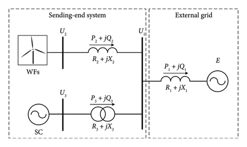
To introduce the system model and the designed model predictive controller, the topology of studied system needs to be clarified first. To reduce computational burden, a single-machine equivalent model is typically constructed to represent the characteristics of WFs instead of modeling each wind turbine. Similarly, for the external power grid, a single-machine infinite bus equivalent model is used for simplification. The simplified network topology of sending-end system with WFs and SC is shown in Figure 1.
2.2. Differential Equations of System
Since the SC is a special type of SG that does not have mechanical power, mechanical power and electromagnetic power are considered to be zero. Based on the characteristics of the SC, it is known that and Iq are considered to be zero. Since the change in active power is very small, the variation in rotor angular velocity is also minimal. Therefore, the change in the power angle δ is also small and can be considered as a disturbance. Similarly, and Vd can be neglected.
The equations contain the algebraic variables v, which are not in the standard form of state space equations. To design an model predictive controller and ESO, it is important to find the relationship between x and v, and substitute v with x to construct the state space equations.
2.3. Algebraic Equations of System
2.4. Extended State Space Model
To design an model predictive controller, the dynamic behavior of the system needs to be described. Combining equations (15), (16) and (22), the constructed DAE represent the dynamic behavior of the system. With the linearized power flow equations, algebraic variables can be represented by state variables, and the extended state space model can be developed for the system.
3. Model Predictive Coordinated Excitation Controller for SC
3.1. Model Predictive Excitation Control of SC
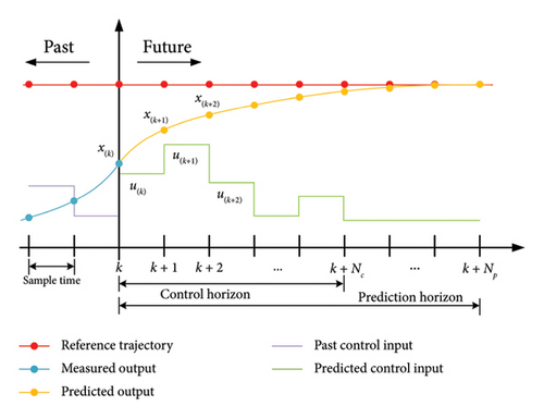
MPC is an advanced control method widely used in industry, it is an optimal control strategy. With the state space equations describing the system’s dynamic behavior, the model predictive controller can predict the system state and determine an optimal control sequence over a finite time horizon by solving an optimization problem at each time step. MPC performs control through rolling optimization, enabling it to maintain strong control performance even in the presence of model inaccuracies, demonstrating robust capabilities. Figure 2 shows the scheme of MPC, where Nc and Np are the control horizon and prediction horizon, respectively. x(k) and u(k) are the system states and control input as time step k. At time step k, the controller uses the current state variables to predict the future changes in the system over Np time steps, generating a control sequence over Nc time steps to optimize system performance. For timely control and feedback from the system, model predictive controller outputs the first control order in the predicted control sequence to the system and waits the for measured states of the system in the next time step.
3.2. ESO for Coordination Control
The model predictive controller returns an optimal control sequence by inputting the current state of the system and predicting its future behavior. However, not all system states can be observed directly. The electromotive force is an inner state of the SC and can not be measured directly. The reactive power output Q2 of the WFs requires the communication between SC and WFs. The excitation controller of SC generally operates without external communication, and communication delays may worsen the control result. Additionally, the disturbances in the system are unmeasurable by the SC. To ensure the model predictive controller of the SC functions properly, it is important to design and apply an ESO for the controller to observe the system states and extended disturbance state.
By performing pole placement for the eigenvalues of the matrix , the observer gain matrix L can be determined. The poles are placed in the left half of the complex plane, and the further left they are, the faster the ESO responds. However, this also increases the noise sensitivity. For the ESO to effectively estimate the state of system and send them to the model predictive controller, the response time of the ESO must be faster than the sample time of the MPC, the bandwidth should ensure that the ESO responds fast to the system dynamics while minimizing noise.
3.3. Excitation Controller Structure of SC
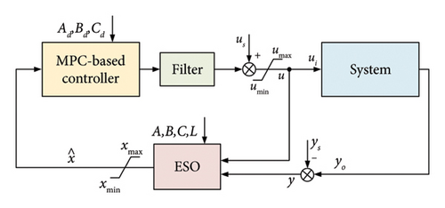
With the above model predictive excitation control strategy and ESO for the coordination control method, the complete excitation controller for SC can be presented in the block diagrams shown in Figure 3.
- 1.
Model Predictive Controller: The discrete-time state space model , and is preset in the controller, and the matrices H and F are calculated in advance. When the controller is operating, it receives the estimated state vector and generates the and H to solve QP for optimal control sequence. After obtaining the optimal control sequence, the model predictive controller outputs the first element in the sequence into the filter.
- 2.
Filter: The control input from the model predictive controller is in discrete time, but the system and the ESO operate in continuous time. Therefore, it is necessary to smooth the control input to reduce the impact of discrete control on the system. In this paper, a first-order low-pass filter is used to smooth the control input. It can be written as follows:
() -
Where τ is the filter time constant. Behind the filter is a saturation block which limits the upper and lower outputs of the signal. To protect the system and avoid excessive input, the control input is limited within the lower limit umin and the upper limit umax. The control input u is sent directly to the ESO and to the system by adding the specified operating state value us.
- 3.
ESO: The continuous-time state space model , , and observer gain matrix L are preset in the ESO. It receives the control input u and system output , estimating the extended system states. There is a saturation block behind the ESO that limits the estimated system states within and . The output is in continuous time and is sampled as the input of model predictive controller at each sample time.
- 4.
System: The system is the real SC, which provides reactive power to the sending-end system for voltage support. It controls the field voltage to change the reactive power inject into the system, mitigating the voltage fluctuation and providing reactive power support in emergencies.Since real-world system contains noise, system output can be processed through a low-pass filter before being fed into the ESO.
4. Case Study
4.1. Test System
In this section, the proposed model predictive excitation controller for SC coordinated with WFs is verified. The test system is built in MATLAB/Simulink software. The topology of the test system is shown in Figure 1, and the specific system parameters are listed in Table 1.
| Items | Symbol | Values |
|---|---|---|
| Base power of system | Sbase | 300 MVA |
| Base voltage of system | Ubase | 220 kV |
| Equivalent AC voltage | E | 1.0 p.u. |
| Impedance between PoC and grid | X1 | j0.5 p.u. |
| Impedance between WFs and PoC | X2 | j0.05 p.u. |
| Transformer leakage inductance | X3 | j0.02 p.u. |
| WFs time constant | Ts | 0.05 |
| Droop coefficient | K | 2 |
The detailed parameters of the SC utilized in the simulation as a controller system are shown in Table 2.
| Items | Symbol | Values |
|---|---|---|
| Nominal power | SN | 100 MVA |
| Rated voltage | UN | 20 kV |
| Inertial coefficient | H | 2 s |
| d-axis synchronous reactance | xd | 2.24 p.u. |
| d-axis transient reactance | 0.17 p.u. | |
| d-axis subtransient reactance | 0.12 p.u. | |
| q-axis synchronous reactance | xq | 1.02 p.u. |
| q-axis transient reactance | 0.15 p.u. | |
| q-axis subtransient reactance | 0.13 p.u. | |
| d-axis transient open-circuit time constant | 8.807 s | |
| d-axis subtransient open-circuit time constant | 0.042 s | |
| q-axis transient open-circuit time constant | 0.85 s | |
| q-axis subtransient open-circuit time constant | 0.05 s |
Table 3 describes the parameters of model predictive excitation controller in the test system. The L matrix of the ESO is obtained through pole placement, with the poles selected based on empirical values to ensure that the system responds quickly while maintaining low noise levels. The function quadprog in MATLAB is employed to solve the QP in MPC.
| Items | Symbol | Values |
|---|---|---|
| Control and prediction horizon | Nc, Np | 10 |
| Weight matrix of state | Ω | diag([100, ⋯, 100]) |
| Weight matrix of control | Ψ | diag([0.1, ⋯, 0.1]) |
| Sample time | Tsample | 20 ms |
| Filter constant time | τ | 0.04 |
| Upper limitations of control input | umax | 12 |
| Lower limitations of control input | umin | −12 |
| Pole placement of ESO | [p1, p2, p3] | [−30, −40, −50] |
| Upper limitation of states | [2, 1.2, 10] | |
| Lower limitation of states | [−2, −1.2, −10] |
- 1.
Small disturbance scenario: The active power of the WFs drops to 0.8 p.u. at t = 1.0 s which resulting in an increase in the system voltage level, rises to 1.2 p.u. at t = 2.0 s which resulting in an decrease in the system voltage level, and recovers to 1.0 p.u. at t = 3.0 s.
- 2.
Large disturbance scenario: A three-phase short circuit fault occurs at the PoC with an impedance of 0.2 p.u. to ground at t = 1.0 s, and the fault is cleared after 0.1 s. During the fault, the active power output of the WFs drops down to 0. The active power output of WFs then recovers to the 1.0 p.u. with a rising rate of 1.0 p.u./s.
To verify the effectiveness and superiority of the proposed control strategy, the classical ST1C excitation controller using realistic control parameters is employed for comparison [31]. The main regulator parameters KA and TA are set to 30 and 0.02, respectively.
4.2. Control Performance Under Small Disturbances
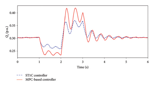
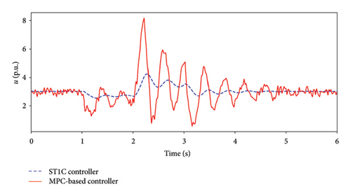
The stochastic active power output of the WFs brings small-disturbance to the sending-end system. The first scenario is employed to verify the capability of the proposed model predictive excitation controller in suppressing small-disturbances in system. Figure 4 displays the terminal voltage, reactive power and control input of SC under both controller during small-disturbance.
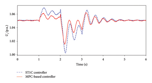
The terminal voltage responses of both controllers are shown in Figure 4(a). At t = 1.0 s, the active power output of WFs drops to 0.8 p.u., leading to a light load and voltage rise in the system. Conversely, at t = 2.0 s, the active power output of the WFs rises to 1.2 p.u., causing the voltage to drop. During the voltage rise, the terminal voltage of SC with the proposed controller is lower than with the ST1C controller, with the highest value being 1.062 p.u. under proposed controller and 1.069 p.u. under the ST1C controller. During the voltage drop, the terminal voltage with the proposed controller is higher than with the ST1C controller, with the lowest voltage value being 1.015 p.u. and 1.0 p.u., respectively. It is evident that the model predictive excitation controller performs better performance in the small-disturbance scenario.
Figure 4(b) shows the reactive power output. Comparatively, the proposed method more effectively provides reactive power support under small disturbances. Specifically, the model predictive excitation controller reduces and provides the reactive power output quickly and sufficiently. The reactive power decreases to 0.23 p.u. and increases to 0.42 p.u. during voltage rise and drop durations, while the ST1C controller achieves 0.26 p.u. and 0.37 p.u. As shown in Figure 4(c), the control input of the SC with the model predictive excitation controller responds faster and more sharply than with the ST1C controller. The ST1C controller has the inertial element and the fixed proportion, which limit the system’s response speed. The proposed controller can respond directly to state changes and adjust the control input by predicting the future behavior of system. This allows for a fast response and sharper change in control input, resulting in better performance of the proposed controller.
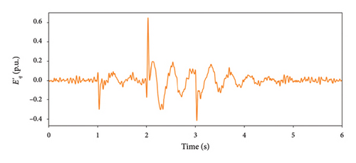
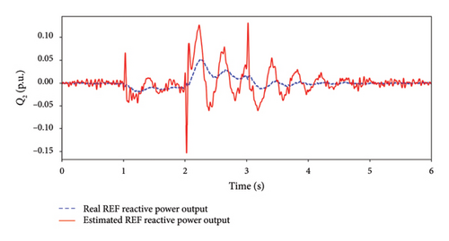
Figure 5 shows the estimated states of the ESO under small-disturbance. The estimated states are all in the steady states before the disturbance and will achieve stability after the disturbance. Because the swing of SC rotor angle is neglected in the Extended state space model, each estimated state contains an oscillating component during small-disturbance. The real and estimated WFs reactive power outputs are shown in Figure 5(b). This illustrates that the ESO can estimate the real state in steady state during small-disturbance. It verifies that the proposed controller can observe the reactive power output of the WFs and make decisions for coordinated control.
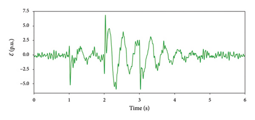
4.3. Control Performance Under Large Disturbances
The voltage support capability of the SC with the model predictive excitation controller under large-disturbance is discussed in this section. A three-phase short-circuit fault at the PoC is set as a large-disturbance to the system. When the fault occurs, the voltage drops sharply, and the SC and WFs inject large amounts of reactive power to support voltage, while the WFs reduces its active power output to provide more reactive power. After fault clearance, the voltage recovers quickly, but the reactive power output cannot be withdrawn immediately, and the active power output remains at a low level. These factors lead to over-voltage in the sending-end system. The terminal voltage and reactive power output responses of the SC and WFs under different controllers during large-disturbance are shown in Figures 6 and 7.
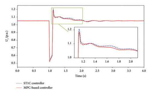
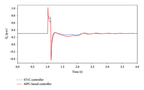
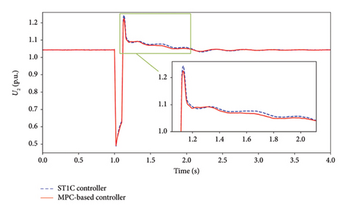
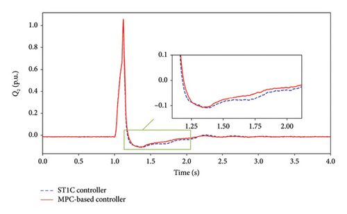
Figure 6(a) displays the terminal voltage of the SC under both controllers. When the fault occurs, the voltage drops to 0.52 p.u. and gradually rises during fault due to increasing reactive power injection. The voltage of the SC under the ST1C controller and the proposed controller rises to 1.205 p.u. and 1.183 p.u., respectively. During the recovery period, the voltage controlled by the model predictive controller is almost consistently lower than controlled by the ST1C controller. Figure 6(b) clearly illustrates that the proposed controller provides more reactive power support to mitigate the over-voltage and accelerate the voltage recovery after fault clearance. The proposed model predictive controller has a fast response capability and can fully utilize its reactive power support capability under large-disturbance.
The terminal voltage of the WFs is shown in Figure 7(a), it drops to 0.49 p.u. when the fault occurs. After the fault is cleared, the voltage of the WFs rises to a maximum of 1.224 p.u. under the proposed controller and 1.243 p.u. under the ST1C controller. During the recovery process, the voltage under the proposed controller recovers faster than under the ST1C controller. Figure 7(b) illustrates the reactive power output of the WFs under both controllers. Due to the coordination of the SC and WFs under the model predictive excitation controller, the WFs achieves better voltage performance in overvoltage suppression and faster recovery with less reactive power output compared to the ST1C controller.
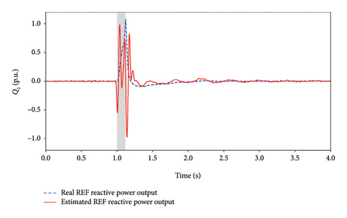
To observe the state estimation capability of the ESO under large-disturbance, the real and estimated WFs reactive power outputs under large-disturbance are shown in Figure 8. During the large-disturbance, significant model mismatch occurs, preventing the ESO from accurately estimating the states. In this period, the estimated state oscillates severely. After fault clearance, the ESO recovers quickly, accurately estimating and fast tracking the actual value of the WFs reactive power output, providing proper information to the MPC for optimal determination. However, if a fault causes a line disconnection, the control strategy will become ineffective until the line is restored.
5. Conclusions
This paper proposes a novel model predictive excitation controller that coordinates with WFs without communication to provide reactive power support and suppress voltage fluctuations in sending-end system. The proposed controller is tested in time-domain simulations in MATLAB/Simulink under small and large disturbances, and compared with the traditional ST1C controller. It achieves superior performance in mitigating fluctuations, suppressing over-voltage and providing reactive power support.
The proposed control strategy, utilizing an ESO, is capable of estimating the reactive power output of WFs under varying levels of disturbances. Upon system recovery, it can rapidly track the actual values, enabling noncommunication coordination between the SC and WFs and effectively avoiding issues associated with communication delays. The model predictive excitation controller predicts the future operating states of the system through state-space equations, solve for the optimal control sequence, and perform rolling control to actively provide reactive power support, suppress voltage fluctuations, and prevent over-voltage. Compared to traditional control methods, which exhibit inherent inertia and delays, the proposed controller can achieve fast and accurate control of the SC by solving linear optimization problems.
In future works, a power system stabilizer will be considered to mitigate the oscillation of the SC for a more accuracy model. Additionally, the rotor angle swing will be taken into consideration.
Conflicts of Interest
The authors declare no conflicts of interest.
Author Contributions
All authors have contributed equally.
Funding
This study was funded by the Natural Science Foundation of Zhejiang Province under Grant LY22E070006.
Acknowledgments
This study was funded by the Natural Science Foundation of Zhejiang Province under Grant LY22E070006.
Open Research
Data Availability Statement
The data used to support the findings of this study are available from the corresponding author upon reasonable request.


