Stability Domain Construction and Tuning for External Loop Controller Parameters Based on Permanent Magnet Wind Power Generation Systems
Abstract
Based on the closed-loop frequency domain model of permanent magnet synchronous generator–based wind power generation system (PMSG-WPGS), the stability domain of the control parameters is constructed through the D-partition method in this paper to acquire the range of machine-side converter (MSC) and grid-side converter (GSC) parameters. First, the basic stability domain of the controller parameters is established according to the control structure and transfer function of the back-to-back converter. Then, based on the frequency domain performance indexes, amplitude margin and phase angle margin, the obtained basic stability domain is adjusted to further gain the control parameter values that meet the frequency domain index. Furthermore, the rationality of the stability domain range is verified by drawing root locus curves of variable controller parameters on the machine side and grid side. Finally, the low-power scale experimental platform of PMSG-WPGS is built in the lab to validate the feasibility of the proposed stability domain construction method.
1. Introduction
With the continuous development of renewable energy, wind power has become an important solution to solve the energy crisis [1–3]. Due to the expansion of modern large-scale wind farms, many recent research studies have focused on the stability of wind power grid-connected operation. In fact, the wind turbine (WT) generator system is a complex nonlinear system, and its stability is related to many factors, such as wind speed, tip speed ratio, control parameters, and grid impedance [4, 5]. Therefore, it is necessary to optimize the control parameters to ensure that the WT captures the maximum wind energy on the basis of stable operation [6]. Control parameters of the permanent magnet synchronous generator–based wind power generation system (PMSG-WPGS) have important impacts on WT speed, wind energy utilization coefficient, and system stability. Appropriate proportional–integral (PI) control parameters can ensure the stable operation of WTs, improve dynamic response speed, and even smooth output power. Therefore, the reasonable value of control parameters has always been one of the key research directions of experts and scholars [7].
The controllers of either grid-side converter (GSC) or machine-side converter (MSC) generally include multiple PI controllers, both of which have an influence on the stability of the wind power system. The selection of their control parameters is directly related to the regulation effect of the whole system. Many methods for parameter design of PI controllers have certain limitations. For example, the pole placement method used in [8] considers and analyzes a large number of parameters and also determines the complex position relationship between zeros and poles. However, the realization of the expected performance index is highly dependent on the setting of dominant poles, and the calculation process is cumbersome. Based on the pole assignment method in [9], the characteristic equation of GSC is established, and the limiting conditions of phase-locked loop (PLL) control parameters are obtained, but the initial values of parameters such as coefficient and frequency need to be determined through trial and error. The optimal value cannot be found within a short period, and the computational complexity is also quite high. The authors in [10–12] adopt the root locus method and Nyquist diagrams, but they can only analyze and explain the impact of a certain parameter on the stability of PMSG, ignoring the coupling effects between parameters, without giving comprehensive consideration to all performance indicators for overall setting design.
The reasonable value of control parameters often has a certain interval range, so the concept of stability domain needs to be considered for the tuning of multiple control parameters. In [13], the stability domain of harmonic resonance parameters is adjusted by introducing the extended disk theorem. Based on the Lyapunov stability theory and Gail disk theorem, sufficient conditions for dynamic system stability are derived, which avoids eigenvalue calculation and improves calculation efficiency. The work in [14] establishes a small signal state-space model of the PMSG, identifies the oscillation modes of the system by using participation factors, and gives the limited value boundary between all the oscillation modes, the integral parameters, and the compensation degree. In [15], a visual tuning method of control parameters is proposed for the controller of the HVDC system. The stable set of parameters is determined by establishing the stable boundary curve on the PI parameter plane. Reference [16] proposes a graphical method to compute the stabilizing values of PI controller parameters for a single-area load frequency control (LFC) system with time delay, which is based on the stability boundary locus to determine the parameter set of the PI controller. The work in [17] uses the parameter space method to carry out multiobjective optimization design for the system in the compensated grid and obtains the intuitive impact on the overall performance of the system when the control conditions or parameters change. Based on the D-partition method, reference [18] derives the parameter stability domain of GSC in different modes under the constraints of multiple performance indexes such as phase margin, amplitude margin, current-loop bandwidth, and PLL bandwidth. Reference [19] considers the different parameters of WTs in the wind farm and analyzes the different oscillation responses and the corresponding parameter value stability domain based on the Rouse–Hurwitz criterion. A stability domain analysis method is proposed based on the participation factor and the characteristic root of the DC microgrid system in [20]. Although the influence of multiple system parameters on system stability is studied, the focus is not on the value range of PI controller parameters. The study of the stability domain of control parameters can also prevent saturation of controller inputs and outputs, avoid system instability caused by controller output exceeding limits, and prevent damage to equipment caused by excessive electrical quantities [21, 22].
Based on the D-partition method, this paper studies the parameter stability domain design of controllers of MSG and GSC of the wind power system. The main contributions of this paper can be summarized as follows: (1) the relationship between control parameters and stability is studied, and a quantitative relationship between control parameters and stability margin is constructed based on the variable separation method; (2) on the basis of quantitative modeling, comprehensive amplitude margin and phase margin indicators are used to construct stable operating ranges for control parameters on the machine side and grid side, which can effectively guide engineering applications; and (3) low-power scale experimental platform is built to verify the modal analysis results.
The rest of the paper is organized as follows: Section 2 presents the frequency domain model of grid-connected side and the PMSG speed regulation system. In Section 3, the parameter stability domain of the controller is solved based on the control structure and transfer function of the back-to-back converter. Then, the stability domain is adjusted based on the frequency domain energy index, namely, amplitude margin and phase angle margin, and the range of domain is further limited. Section 4 verifies the rationality of the stability domain by drawing the parameter root locus. In Section 5, the feasibility of the method and the rationality of the stability domain are further verified by the experimental platform of the PMSG built in the lab. Conclusions are drawn in Section 6.
2. Wind Power Control System Description
The structure of the PMSG-WPGS is demonstrated in Figure 1. It is mainly composed of WT, PMSG, and power conversion device. PMSG is connected to the power system through the back-to-back converter. Due to the existence of DC capacitance, the machine side and the grid side are decoupled. Therefore, the stability of them will be analyzed separately below.

2.1. Closed-Loop Control Structure of GSC
The GSC adopts a double-loop control structure as shown in Figure 2. The current inner loop is controlled to ensure that the output current can track the reference current input in real time. The DC outer control loop is to maintain the DC bus voltage constant [23]. When the wind system works normally, the modulation area of the back-to-back converter is not saturated, so the currents of the d and q axes can be decoupled. At the same time, because the transfer function structure of the target object controlled by the d-axis and q-axis current inner loop is the same, the structure and parameters of the two current controllers can be unified and the same design method can be adopted. Based on this similarity, the paper will take the d-axis current control link as an example.
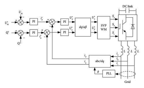
While designing the current inner-loop controller, the time constant of the GSC itself needs to be considered. Generally, the time constant is approximately 1/2 of the switching cycle [24]. Next, this paper will take the double-loop control structure of the d-axis as the research object, decouple the control of the current loop, and analyze the equivalent structure diagram of the current inner loop and its open-loop transfer function.
Figure 3 presents the control structure diagram of the current inner loop. PI is the controller of the current inner loop, and the proportional parameters and integral parameters of the controller are recorded as Kp1 and Ki1, respectively. is the current reference value given by the voltage outer loop. KPWM is the equivalent amplification factor of the converter, which represents the ratio between the amplitude of the output DC voltage and the carrier amplitude. When using SVPWM modulation, its value is 1. TS is the switching cycle of the converter, which is related to the switching frequency of the inverter and is an inherent parameter related to the system. R and L are the resistance and inductance of the converter, respectively.

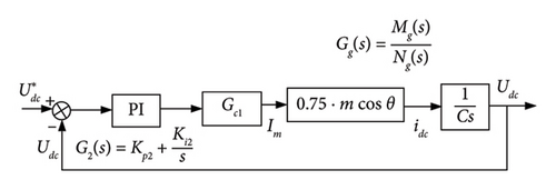
The voltage outer loop of the GSC is mainly to ensure the constant DC-side voltage Udc so that the capacitor can be regarded as a constant voltage source to filter out the interference of harmonic and other redundant signals while setting the voltage. The current inner loop is equivalent to Gc1, so the closed-loop control structure block diagram of the voltage outer loop can be obtained, as shown in Figure 4.

After the transfer function models of the inner current loop and the outer voltage loop at the grid side are obtained, the PI controller parameters of the outer voltage loop can be adjusted according to the control principle of the closed-loop system, and the stability domain of the controller parameters Kp2 and Ki2 can be preliminarily obtained.
2.2. Closed-Loop Control Structure of MSC
The power obtained by the front end of the direct-drive permanent magnet wind power system is the maximum wind energy captured by WT, and the control module adopts a maximum power point tracking (MPPT) control strategy. That is to ensure WT can achieve the optimal tip speed ratio under different pitch angles and the best value of wind energy conversion rate. The machine-side control structure block diagram of the back-to-back converter adopted at the rear end is shown in Figure 5.
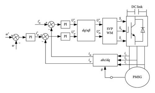
As can be seen from Figure 5, the MSC also adopts double-loop control which contains the current inner loop and speed outer loop. The function of the speed outer loop is to provide a current reference value for the current inner loop. The inner loop controls the current according to the output signal of the speed outer loop to improve the dynamic response performance. Vector control is adopted in the current inner loop to make , in which case the active power, reactive power, and electromagnetic torque can be adjusted by controlling iqs, and then, the speed can be adjusted. The speed outer loop usually adopts the same cascade structure as the grid-side voltage outer loop to track the rapid change in q-axis current.
As in the inner loop of MSC, the current loop requires the rapidity of dynamic response frequency, which is directly related to the dynamic performance of the whole system. Generally, in the machine-side control system, the adjustment speed of the speed loop is slower than the change speed of the current inner loop. Therefore, when studying the effect of on iq, we can only focus on the current feedback signal and ignore the change in the back electromotive force contained in the current loop. Then, the current inner-loop control structure is shown in Figure 6(a).


By comparing the rotor speed reference value with ω, through the outer-loop controller, the q-axis current reference value of the PMSG is obtained. With the current loop as an inner loop of the speed outer-loop control, the whole generator-side closed-loop control structure diagram to realize MPPT control is shown in Figure 6(b).
In Figure 6(b), J is the moment of inertia, np is the pole number, ψf is the magnetic linkage, and T0 is the no-load torque.
After the transfer function models of the internal current loop and the external speed loop are obtained, the PI controller parameters of the external loop can be adjusted according to the control principle of the closed-loop system, and the stability domain of the controller parameters Kp4 and Ki4 can be preliminarily obtained.
3. Stability Domain Construction and Tuning of Controller Parameters
3.1. Calculation Flow of Stability Domain
Since the machine side and the grid side have the same transfer function structure, composed of an outer loop and an inner loop, their stability domain designs are similar. Therefore, this section first gives a unified control parameter design method, laying the foundation for the following parameter design.
By constructing the characteristic equation of the closed-loop transfer function, the D-partition boundary and parameter stability domain of the system can be obtained, and the simultaneous optimization design of multiple performance indicators can be achieved. The basic principle is described as follows.
It is assumed that the control structure of a control system is a closed-loop feedback composed of input signal R, controller PI, controlled object G, and output signal Y, as shown in Figure 7. R can be compared to DC voltage or speed, so that the machine side and grid side can be analyzed in a unified way.

Kp and Ki obtained by solving the equation are related to the frequency ω, and they are independent. That means the proportional coefficient and integral coefficient of the control system are decoupled, so as to prepare for the next step to determine the stability domain of the controller parameters. In order to find the stability domain, it is important to ensure that the closed-loop characteristic equation (14) does not contain the zero point of the right half plane. At the same time, solve the two equations in equation (17), draw the stability boundary curve in the Kp − Ki plane according to the change in frequency, and the domain composed of the parameter points which stabilize the system within its envelope is the stability domain of Kp − Ki.
In the next step, the above stability domain will be adjusted to meet the frequency domain performance. In the obtained basic stability domain, the frequency domain performance indexes, i.e., amplitude margin and phase angle margin, are used as the objective functions, and the amplitude margin Am and phase angle margin φm are used to further limit and optimize the Ki and Kp parameters to make them flexibly meet the expected performance indicators. The specific solution and setting method are as follows.
Given that Am and φm are in the expected range, for large enough ω, the curves of Am and φm are drawn by using equations (19) and (20). Then, based on the stability domain obtained at the beginning, ω values are selected according to the requirements of closed-loop bandwidth. These two groups of curves can be presented in the same plane to form the Kp − Ki stability domain limited by amplitude margin and phase angle margin at the same time and determine the parameters of PI controllers that meet the requirements.
Next, taking the PMSG-WPGS as the object, according to the above process, the stability domain of the equivalent outer-loop controller parameters on the grid side and the machine side will be analyzed and studied, respectively.
3.2. Stability Domain for Grid-Side Control Parameters
The control objectives on the network side include maintaining stable DC voltage and grid connection with a unity power factor. Without considering the impact of weak current networks, this article believes that PLLs can correctly track system voltage, and the grid-side parameters are shown in Table 1. Therefore, only the impact of the control system on stability needs to be considered.
| Resistance R (Ω) | 0.0035 |
| Inductance L (mH) | 0.3 |
| DC voltage reference value (V) | 1200 |
| Voltage gain KPWM | 1200 |
| Switching cycle Ts (s) | 1/6000 |
Based on the transfer function model of the grid-side current inner loop and voltage outer loop obtained in Section 2, the PI controller parameters of the voltage outer loop can be adjusted according to the stability domain solution method. By separating variables, the stability domain of controller parameters Kp2 and Ki2 can be preliminarily obtained.
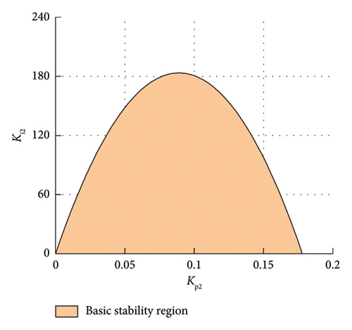
When the frequency changes, the basic stability domain of the controller parameter Kp2 − Ki2 can be drawn according to equation (27), as shown in Figure 9(a). The abscissa is the proportional parameter Kp2 of the outer-loop controller, and the ordinate is the integral parameter Ki2.
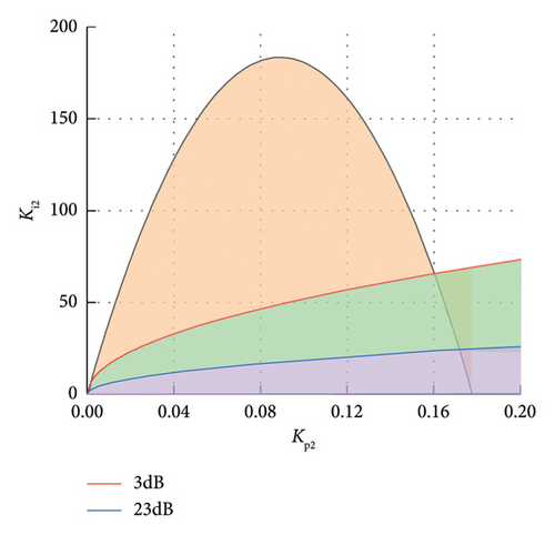
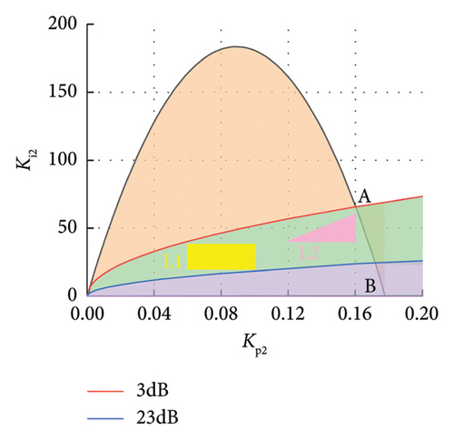
According to experience, take Am as 3–23 dB and φm as 30°–60°. For large enough ω, use equations (28) and (29) to draw two groups of curves of Am and φm. Then, based on the obtained stability domain diagram, draw the boundary curve of the setting stability domain based on the frequency domain index in the same Kp − Ki plane by selecting the value of ω according to the expected closed-loop bandwidth. The stability domain delineated by the basic stability domain and frequency domain indexes, i.e., amplitude margin and phase angle margin, is obtained, as shown in Figure 9(b). And the green-shaded part (excluding the part outside the boundary line of the basic stability region) is the stability domain of the PI controller that meets the indicators. In the stability domain, the system has good dynamic response performance on the basis of stable operation.
3.3. Stability Domain for Machine-Side Control Parameters
Similarly, based on the transfer function model of the machine-side current inner loop and speed outer loop obtained in Section 2, the PI controller parameters of the speed outer loop can be adjusted according to the above stability domain solution method. Then, the stability domain of controller parameters Kp4 and Ki4 can be preliminarily obtained.

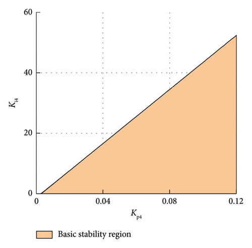
The expressions of parameters Kp4 and Ki4 of the generator-side voltage outer-loop controller can be obtained from equations (3), (33), and (45). When the frequency changes, draw the basic stability domain of controller parameter Kp4 − Ki4 according to the expression of control parameters, as shown in Figure 11(a). The abscissa is the proportional parameter Kp4 of the outer-loop controller, and the ordinate is the integral parameter Ki4.
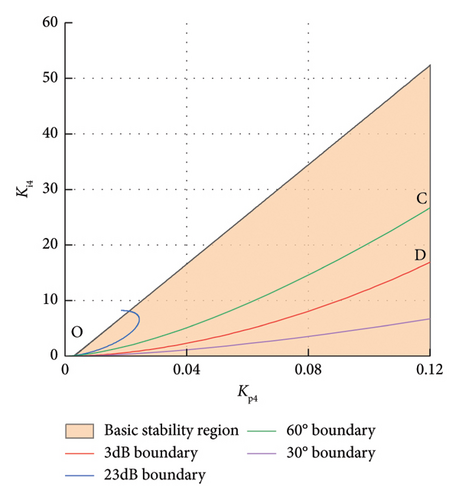
Next, the stability domain obtained above will be further adjusted from the perspective of frequency domain performance, that is, the amplitude margin and phase angle margin in the frequency domain will be considered. Substituting equations (33) and (34) into the calculation equations (19) and (20) of amplitude margin and phase angle margin, respectively, the expressions of parameters Kp4 and Ki4 under the speed outer-loop controller can be obtained. Take Am as 3–23 dB and φm as 30°–60°. For large enough ω, use the expressions of Kp4 and Ki4 to draw two groups of curves of Am and φm, which is shown in four color curves in Figure 11(b).
Then, based on the obtained stability domain diagram, present the boundary curve of the setting stability domain based on the frequency domain index in the same plane. The Kp − Ki stability domain (the orange part surrounded by the origin O, C, and D) delineated simultaneously by the basic stability domain and the frequency domain indexes, i.e., amplitude margin and phase angle margin, is the PI controller parameter stability domain that meets the indicators, as shown in Figure 11(b).
After the above deduction and calculation, the variation range of control parameters for the stable operation of the generator side and grid side is established. However, the main concern of this paper is the security and stability of the system, so there is no further evaluation of the dynamic performance of the parameters in the stability domain.
4. Verification of Root Locus Based on Stability Domain
The stability domains of grid-side and machine-side controller parameters obtained in the previous section will be verified, respectively, mainly using the method of variable control parameter root locus.
4.1. Verification of Grid-Side Control
The root locus curve is used to verify the stability domain obtained in Section 3 and check whether the obtained stability domain meets the stable indicators of the grid-side system from the perspective of frequency domain.
This section mainly focuses on the parameters of the outer-loop controller. Therefore, the selection of the controller parameters Kp1 and Ki1 of the current inner loop at the grid side does not follow the method described in Section 3. The selection principles of these two control parameters are as follows.
The root locus of variable parameter Kp1 in the current inner-loop control system can be obtained, as shown in Figure 12.
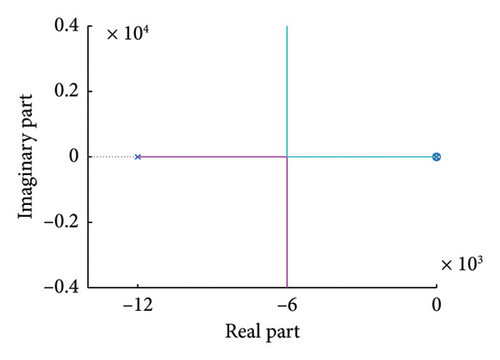
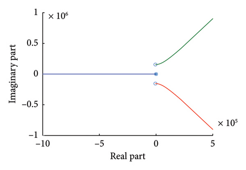
It can be seen from Figure 12(a) that the variable Kp1 root locus is on the left half of the complex plane, which shows that the value of Kp1 has no effect on the stability of the current inner-loop system at the grid side, and Kp1 can take any value when Ti1 = 1.
Through the same derivation and drawing, the root locus of variable parameter Ti in the current inner-loop control system can be obtained, as shown in Figure 12(b).
It can be seen that part of the roots of the variable Kp1 root locus is on the right half of the complex plane, that is, there are roots with the real part greater than 0, which indicates that the value of Ti has a great impact on the stability of the current inner-loop system at the grid side, and the value of Kp1 is limited in scope. The critical stable open-loop gain is found in Figure 12(b), and the calculated value of Ti1 should be between (0.0008, 10).
In order to verify the rationality of the parameter stability domain of the voltage outer-loop controller at the grid side, select two value ranges from the stability domain in line with the frequency domain characteristics obtained above. And the two value ranges include the rectangular domain L1 (yellow) and the triangular domain L2 (pink) in Figure 13. Then, observe whether the change of control parameters in the two domains will lead to the instability of the control system by calculating the characteristic roots of the voltage closed-loop control system.
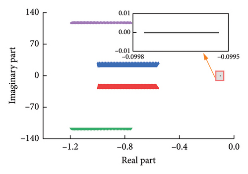
Traverse each group (Kp2, Ki2) in L1 and L2 one by one, and substitute into equation (38) to obtain a series of characteristic roots with the change of Kp2 and Ki2, which is shown in Figure 14. In this stability domain, the control system has two pairs of conjugate complex roots and a real root. It can be seen from Figure 14 that when the control parameters are in the L1 and L2 regions, the real parts of the characteristic roots are all less than 0. This shows that GSC can maintain stable operation, verifying the rationality of the obtained stable region.
4.2. Verification of Machine-Side Control
Similarly, in order to verify the rationality of the parameter stability domain of the machine-side speed outer-loop controller, select the rectangular interval M (yellow in Figure 15) in the stability domain conforming to the frequency domain characteristics obtained above. Then, observe whether the change of control parameters in this domain will lead to the instability of the control system by calculating the characteristic roots of the voltage closed-loop control system.

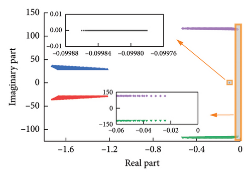
Traverse each group (Kp4, Ki4) in M in Figure 15 one by one, and substitute into equation (39) to obtain a series of characteristic roots with the change of Kp4 and Ki4, which is shown in Figure 16, and enlarge the trajectory near 0.
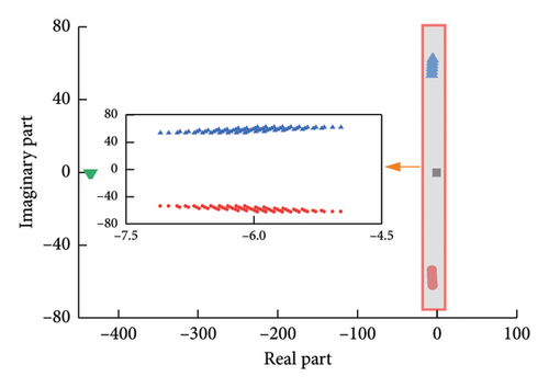
In this stability domain, the control system has a pair of conjugate complex roots and two real roots. It can be seen from Figure 16 that when the control parameters are in region M, the real parts of the characteristic roots are all less than 0. This also shows that MSC can maintain stable operation, verifying the correctness of the obtained stable region.
The above theoretical analysis verifies the effectiveness of the stability domain design method proposed in this paper. It should be noted that this paper focuses on the stable operation of the system. Therefore, the parameter values in the stability domain can ensure the stable operation of the system, while the dynamic response performance is also different due to the difference in the control system bandwidth, such as rise time and adjustment time.
5. Experimental Verification
In order to verify the rationality of the obtained controller parameters stability domain, the experimental platform is built as shown in Figure 17. Two permanent magnet synchronous machines (PMSMs) are connected directly while one machine is arranged as the WT imitator and the other one is adopted to be the wind power generator. The WT imitator is controlled to output the appropriate torque according to the wind speed and machine rotor speed. The direct torque control method is adopted to improve the torque control speed. The proposed control strategy based on the SVPWM shown in Figure 5 is adopted for the wind generator machine.
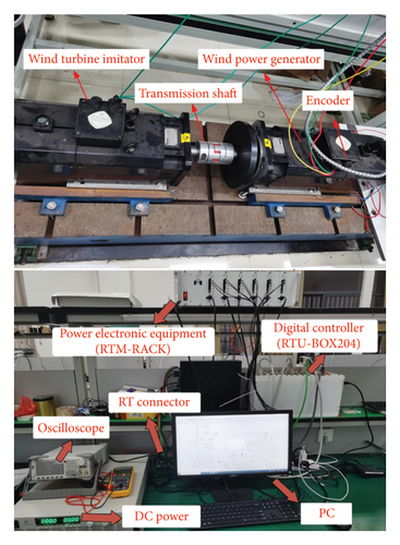
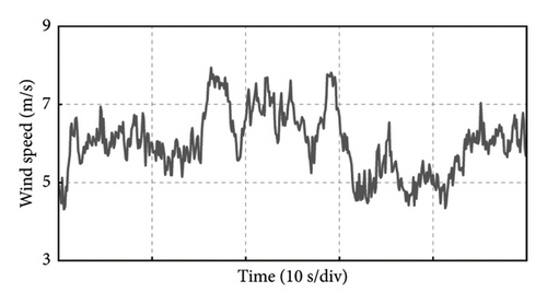
The parameters of the experimental platform are shown in Table 2. Next, the control parameters stability domain of the machine-side speed outer loop obtained by the above method is verified. The stochastic wind speed is given in the experiment which can be seen in Figure 18.
| Wind turbine imitator | |
| Wind turbine blade radius RW (m) | 1.32 |
| Air density ρ (kg/m3) | 1.225 |
| Optimum TSR λopt | 8.1 |
| Optimum coefficient Cp | 0.48 |
| Rated wind speed v (m/s) | 8.53 |
| Rated power Pw (W) | 1000 |
| PMSG | |
| Stator resistance Rs (Ω) | 0.004 |
| Stator inductance Ls (mH) | 0.001 |
| PM flux linkage Φm (Wb) | 0.25 |
| Pole pairs np | 4 |
| Inertia J (kg·m2) | 0.0653 |
| Rated speed wm (r/min) | 500 |
Several groups of PI parameters are selected for experimental verification in the stability domain or unstable domain of the rotor speed controller based on frequency domain tuning.
Group 1: boundary points C and D of the obtained tuning stability domain. The Kp4 value is 0.12 and the Ki4 value is 26.89 at Point C. The Kp4 value is 0.12 and the Ki4 value is 17.33 at Point D. The controller parameters at these two points are, respectively, used to verify in the experimental platform.
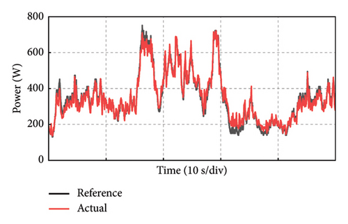
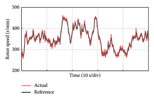
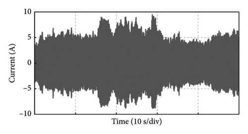
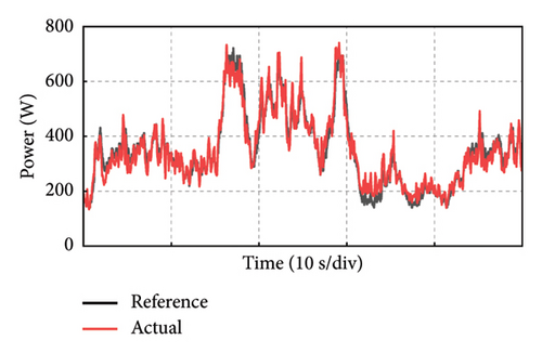
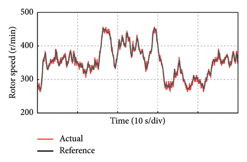
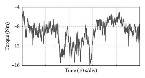
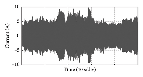
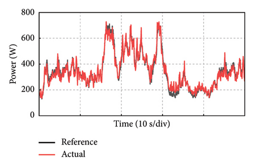
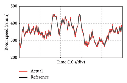
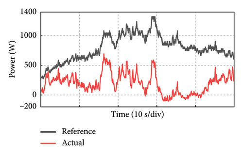
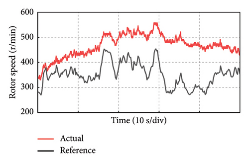
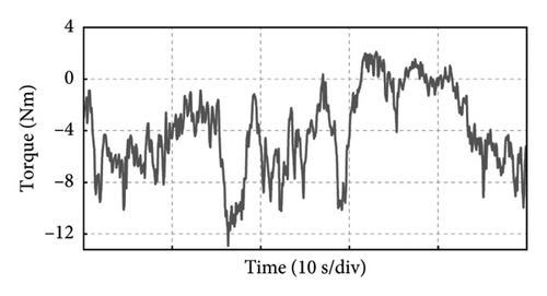
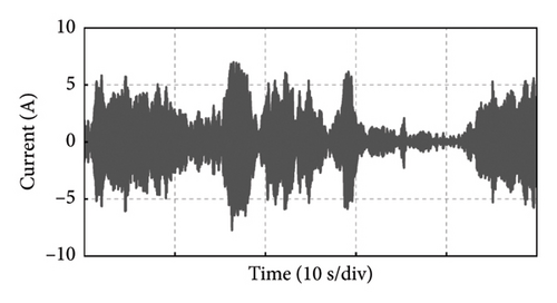
Take the experiment at Point C of Group 1 as an example, and the experimental results in 50 s of the PMSG under the control parameters can be demonstrated in Figure 19. The actual output power of PMSG can track the reference power in real time as shown in Figure 19(a). The rotor speed of PMSG can track the reference value which is varied with the wind speed as shown in Figure 19(b). It can be observed that the control at Point C is realized well. This is because the bandwidth of Point C is larger, so the dynamic performance of the control system is better and the dynamic response speed is faster. The current and torque waveforms of the generator are given in Figures 19(c) and 19(d), respectively. Both the current and electromagnetic torque varied according to the stochastic wind speed as the same as the changing trend of the rotor speed. The below experimental results show that the controller parameters at Point C near the boundary of the stability domain can maintain the stable operation of the wind power system.

Group 2: two points E and F in the obtained tuning stability domain. The Kp4 value is 0.05 and the Ki4 value is 5 at Point E. The Kp4 value is 0.08 and the Ki4 value is 11.88 at Point F. The controller parameters at these two points are, respectively, used to verify in the experimental platform.
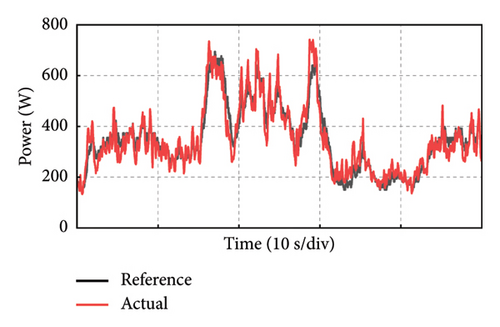
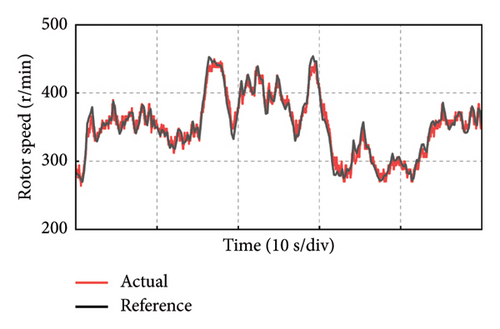
The 50 s experimental results in Point E and Point F are obtained, respectively, as shown in Figures 20 and 21. Similarly, the actual output power and the rotor speed of PMSG can track the reference value. It can be observed that the control effect at Point E and Point F both are realized well, but relatively speaking, the tracking effect is better when the integral parameter value is larger. The below experimental results show that the controller parameters at Point E and Point F in the stability domain can also maintain the stable operation of the wind power system.
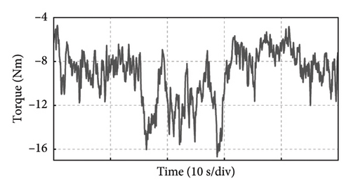
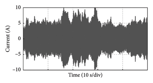
Group 3: boundary points G and H of selected verification range M. The KP4 value is 0.1 and the Ki4 value is 15 at Point G. The Kp4 value is 0.11 and the Ki4 value is 25 at Point H. The controller parameters at these two points are, respectively, used to verify in the experimental platform.
Take the experiment at Point G of Group 3 as an example, and the experimental results in 50 s of the PMSG under the control parameters can be demonstrated in Figure 22. Similarly, it can be observed that the control at Point G is realized well. The below experimental results show that the controller parameters at Point G in the boundary of the selected verification stability domain can also maintain the stable operation of the wind power system.
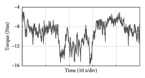
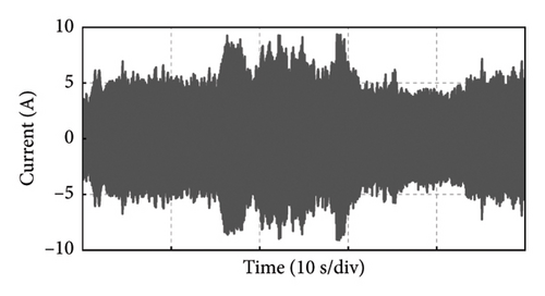
Group 4: Point I in the unstable domain. The Kp4 value is 0.0001 and the Ki4 value is 0.005 at Point I. Next, the wind power system output at the point will be verified in the experimental platform.
The experimental results under the control parameters at Point I are shown in Figure 23. The generator output power waveform in Figure 23(a) and rotor speed waveform in Figure 23(b) show that the actual power and the speed do not track the reference values in real time. After 30 s, the output power is below 0, and the current value of Phase A also fluctuates around the value of 0. Therefore, the controller parameter values at the Point I of the instability interval do not guarantee good and stable tracking effects of the PMSG, which can be seen from these experimental results.
6. Conclusion
In this paper, the PI control parameters of the outer-loop control of PMSG-WPGS are studied from the perspective of the stability domain based on the D-partition method. By the equivalent current inner-loop control of MSC and GSC to the outer-loop control, the model for the study of the parameter stability domain is obtained. Then, by analyzing the closed-loop characteristic equation of the control system, the transfer functions of the grid-side voltage outer-loop and the machine-side speed outer-loop controller are obtained, and the transfer functions are decomposed to obtain the stable boundary curve and the basic stability domain of the control parameters. Next, the basic stability domain is adjusted from the frequency domain performance indexes, i.e., amplitude margin and phase angle margin, and the scope of the stability domain is further limited. Moreover, by drawing the root locus of respective characteristic equations, the results show that the stability domain obtained by this method is reasonable. Finally, the low-power experimental platform is built to verify the scheme and the experimental results validate the feasibility of the proposed stability domain construction method.
In summary, the stability domain construction and tuning method proposed in this paper provides another idea for the design of control parameters of machine-side and grid-side double-loop converter of PMSG-WPGS. The limitation of this article is that it only constructs the stability domain of control parameters from the perspective of stable system operation, lacking consideration for the dynamic performance of the system. In the future, further research can be conducted on the adaptability of parameter tuning methods under different control strategies, and multiobjective stable operation methods with joint optimization of multiple parameters can be considered.
Conflicts of Interest
The authors declare no conflicts of interest.
Funding
This work was supported by the Science and Technology Projects of State Grid Corporation of China (Analysis and Improvement of Regulating and Supporting Capacity under the Background of Flexibility Renovation and Heating Renovation of Large Scale Thermal Power Units) (No. 52018K22001F).
Acknowledgments
This work was supported by the Science and Technology Projects of State Grid Corporation of China (Analysis and Improvement of Regulating and Supporting Capacity under the Background of Flexibility Renovation and Heating Renovation of Large Scale Thermal Power Units) (52018K22001F).
Open Research
Data Availability Statement
We can provide data if the readers request.


