Analysis of Wind Driven Permanent Magnet Synchronous Generator for Power Grid System
Abstract
A permanent magnet synchronous generator (PMSG) is commonly utilized in many wind energy conversion systems (WECS). The main advantage of PMSG is variable-speed operation, and it can be connected directly to the turbine without a gearbox. In this paper, a PMSG is employed to convert wind energy into electrical energy and transmit it to a load through an AC-DC-AC converter. This circuit is modelled and simulated with the help of MATLAB simulation software, and the corresponding results are presented. The proposed method is suitable for microwind turbine applications to minimize landscape and connect PMSGs in parallel for better performance.
1. Introduction
In the past two decades, greater attention has been given to the exploitation of renewable energy sources, particularly wind and solar, for electrical energy conversion. In wind turbine (WT) applications, generators play an important role in converting mechanical energy to electrical energy. The wind energy conversion system’s output power is variable and fluctuates with wind speed. There are two modes of operation for wind energy conversion system (WECS): variable speed and constant speed. Due to their higher capture power and efficiency than fixed-speed WTs, variable-speed WTs are chosen for micro-WT applications [1]. The generators used for the wind system are a doubly fed induction generator (DFIG) [2] for grid-connected applications, a squirrel cage induction generator (SCIG) [3–5], and a permanent magnet synchronous generator (PMSG) [6] both for standalone and grid-connected applications.
Permanent magnets are more expensive than other generator types and require more labour-intensive manufacturing procedures; PMSG prices might be higher. PMSGs are sensitive to changes in temperature. The permanent magnets might demagnetize as a result of high temperatures, which would lower the generator’s effectiveness and efficiency. One of the most promising system architectures now available in the field of wind energy is the PMSG-based WECS, which interfaces with the power grid through a power electronics converter. Permanent magnet synchronous machines that are directly attached to the turbine have become the most popular wind-generating option during the past several years [7–11]. This technology is especially advantageous since it lowers the expense and frequency of maintenance activities. In reality, these generators operate at high power factors and great efficiency since they are self-excited. In addition, a multipolar Generator does not require a gearbox to match the rotor and blade speeds. This benefit becomes essential for the installation of WTs. The needed system stability and power quality may be guaranteed by an effective control approach for the utility converter. The current widely used classical control techniques require that the grid be synchronised without the use of voltage detectors using a method for virtual flux assessment with an inherent sequence difference in the fixed reference frame [12].
Li et al. proposed a predictive active disturbance rejection control approach to maximize wind power extraction in a direct-driven PMSG-based wind energy conversion system. This technique can successfully cope with the impacts of uncertainties in internal dynamics, modelling errors, external forces, and a range of wind speeds [13].
Wang et al. [14] described a novel rectifier architecture for wind energy conversion systems using variable-speed PMSGs. It consists of two three-phase diode bridges and three thyristors. The suggested rectifier offers a number of standout characteristics, including affordability, little power loss, and ease of control. Even when the wind velocity decreases to half of the rated amount, it can still correctly regulate the generator speed to its capacity to cascade the input voltages. The PMSG’s performance can be improved by many controlling mechanisms; hence, we get continuous renewable energy naturally, and the focus on it is also increasing day by day. In recent days, small WTs (< 200 kW) have been employed because of their reduced environmental effect, reduced noise level, grid code and national regulations requiring easier grid connections.
A major growth in the penetration of Wind Power installations into energy delivery networks has been noted by Mahmoud A. Soliman et al. WT generator systems are undergoing intensive research and development in order to improve their performance. This paper presents a novel adaptive fuzzy logic control approach for improving the output of a grid-connected WTs. A suitable power converter is utilised to connect the grid to a PMSG operating with variable wind speed [15].
For a wind power system that uses a PMSG, Wai et al. devised a revolutionary maximum-power-extraction strategy for a wind power system with a PMSG, which comprises the highest error-driven mechanism and an optimum differential-speed control [16]. This approach initiates the system’s output power progressively growing to its highest rate by controlling the flow of current in the direction conferring the change in power, similar to a typical hill-climbing method.
Putri et al. discovered that wind energy conversion systems may extract the most power by managing the rotating speed of the WTs. To enhance the extraction of maximum power, this paper presents a new sensor-less maximum output harvesting control for micro WECS employing a PMSG. In this method, the on and off times of the buck converter are calculated utilising the system voltage and current of a rectifier rather than the characteristics of the WT and the speed of the actual wind. The switch’s on/off time variation depends on the change in power from the phase control rectifier and the preceding duty cycle in order to achieve speedy convergence until the point of maximum power is reached [17]. Further, PMSGs are often employed in VSWTs because they have a high level of reliability, a high torque sensing density, and a simple form [18, 19]. VSWTs are also extensively used in rural areas for off-grid small-scale WTs [20, 21].
Recently, Okedu et al. suggested a fault current limiter for a WT control based on PMSG. A series dynamic brake resistor (SDBR) was employed as the fault current limiter in this investigation [22]. The wind generator’s machine-side and grid-side converters (GSCs) were studied, and the grid voltage was taken into consideration as the SDBR’s switching signal during the transient condition. In both weak and strong grids, the performance of the SDBR has been examined at different network strengths. WTs with PMSG design and model simulation were proposed by Avu et al. [23]. The WT in this case uses PMSG to run at a variable speed. In this method, to utilize the most amount of wind energy feasible, it employs the pitch controller to alter the rotation of the WT’s blades.
Jiang et al. have recommended a PMSG-based WT time-sharing frequency coordinated control (TFCC) system to increase wind energy collection while quickly supplying frequency support during disturbances [24]. Then, virtual inertia controls for the rotor and DC connections are presented. The first is a unique adaptive frequency droop control that considers frequency fluctuation. Second, a novel TFCC method that uses the frequency dead-band to coordinate the frequency regulation priorities of the aforementioned three controls is proposed.
In this paper, PMSG is connected to a three-phase diode converter, filter, buck converter and a three-phase inverter. The usage of a larger number of pole pairs allows the PMSG to operate even at a lower speed without reducing efficiency, thereby avoiding the efficiency hence it allows to avoid the usage of gearboxes and other auxiliary equipment and reducing mechanical losses and maintenance costs. The adjustment of PMSG characteristics like voltage and frequency is suggested in this research as a way to improve efficiency and meet load demand.
The main contribution of the study is to simulate the integration of wind-driven PMSG systems with the electrical grid using pitch angle control. The effects on grid stability, power quality and grid code compliance may be evaluated by modifying the Pitch angle. By controlling the pitch angles, the control system can protect the system from severe winds and stop the turbine from overspeeding. This contributes to enhanced scheme consistency and permanence. This study helps maximise the system’s performance in applications connected to the grid by running consistently and reliably. The efficient implementation of PMSG machinery powered by wind serves as proof of the technology’s practicality and efficiency. It promotes wider acceptance of and investment in wind energy projects by showcasing the possibilities for producing renewable energy.
2. Proposed Controller

- i.
The research bases its conclusions on the hypothesis that the system has reached a steady state, where all of the parameters and variables remain constant across time. Transient effects or dynamic behaviours are frequently ignored.
- ii.
The study makes the assumption that the wind is calm and constant, without any turbulence or gusts. In actuality, the generator’s performance can be considerably impacted by changes in wind speed and direction.
- iii.
In the PMSG, there are no magnetic losses and no hysteresis; hence, perfect magnetic coupling is believed to exist. Additionally, for the sake of simplicity, electrical losses like resistance and iron losses are frequently disregarded.
- iv.
The limitations and losses of the actual power electronics converter are ignored.
- v.
Nonsinusoidal waveforms and other nonlinear phenomena like magnetic saturation may be overlooked.
The variations in wind speed have an impact on PMSG’s output frequency and voltage. Many applications require a consistent output voltage, either in DC or AC. In this paper, a closed-loop model is implemented in the buck-boost converter to attain the required constant voltage of the system. The error value is computed in this system by comparing the actual voltage of the buck converter with the reference voltage signals. This voltage is measured by a voltage sensor. The PI controller will then be tasked with processing this error value. The output of the PI controller alters the duty cycle of the buck converter to make its output voltage identical to the reference set voltage (400 V). Because this regulated DC output voltage is required for DC voltage applications, a three-phase insulated gate bipolar transistor (IGBT)-based inverter is used to provide continuous AC output voltage. The output voltage is successfully controlled by the inverter using Sinusoidal PWM (SPWM) control.
The PMSG is coupled to the WT shown in Figure 2, in order to convert wind energy into electrical energy. The base wind speed of the WT is 12 m/s, the wind speed and pitch angle of the WT are 1 and 2 m/s, the mechanical output power of the WT is 8 kW, and the maximum power at the base wind speed is 0.73.
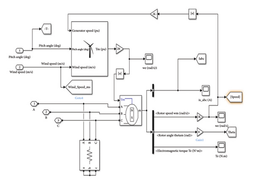
The output voltage obtained from the filter circuits is applied as an input to the step down chopper or buck converter. In some cases, if the output voltage obtained from wind-driven PMSG is less than the nominal voltage, which is decided by the load demand, then a step-down or step-up chopper or buck-boost converter is replaced instead of a buck converter. The control range of the output voltage of the step-down chopper depends on the voltage maintained by the grid system voltage, which is approximately 400 V to 440 V. The step-down chopper is controlled in a closed loop, allowing the system output voltage to match the grid system’s operational voltage precisely. The grid system’s load demand will determine whether more than one PMSG is added to the system.
The DC voltage is applied to a step down chopper converter of L = 0.2 mH, C = 2000 μF which is in a closed-loop system with a PI controller [25–27] as given in Figure 3. The Ziegler–Nichols method is used to fine-tune the PI controller. In this tuning method, initially assume that the value of the integral constant KI is equal to zero while varying the proportional constant from zero to a critical value, Kc, where the output exhibits a sustained periodic oscillation. Now, from zero, the integral constant KI is increased to a certain value where all steady-state error is reasonably eliminated. The results of the Kp and KI values are observed to be 0.009 and 0.125 from these optimizations, respectively.
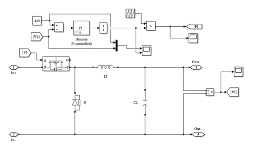
The closed loop is used here to adjust and give constant voltage to the inverter irrespective of whatever the input may be by changing the controller values and output of the buck converter. The output of the buck converter is adjusted to 400 V DC, and it is given to a three phase PWM-inverter operating in 180 mode at 50 kHz switching frequency. It is used because in 180 mode, the number of switches remains constant at all instant. The inverter converts the DC to AC voltage so that line-to-line voltage of 400 V AC and line-to-phase voltage of 230 V AC and a current of 1.2 A are maintained as output, and a frequency of 50 Hz is also maintained if a 3-Phase RLC load of values R = 200 Ω, L = 5 mH, C = 200 μF is connected across the output. The RMS line-to-line and line-to-phase voltages are 263 and 163 V, respectively.
3. Simulation and Results
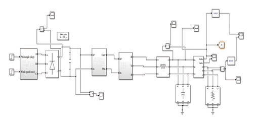
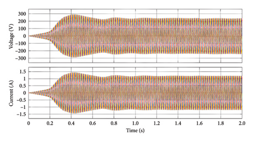
The simulation model of proposed system is displayed in Figure 4. Figure 5 represents output voltage and current waveform of inverter circuit. The DC voltage obtained from the step-down chopper converter is given as input to the three-phase PWM inverter operating at 180 modes, and the output voltage of the inverter is 230 V AC with a current of 1.2 A, and it is maintained at that value. The ode23tb (stiff/TR-BDF-2) solver is used to execute the simulation in discrete mode.
The efficacy of the developed controllers with the observed generator characteristics has been demonstrated by meticulous simulation under a variety of operating circumstances. Table 1 lists the system parameters for the filters, utility grid, WT and PMSG. A complete model is taken into account for the power electronics converter in the simulation model. Simulations have been run to verify the effectiveness of the grid-side converter controllers with active and reactive power regulation, the filter with the mitigation of high-frequency switching harmonics of the inverter output voltage, and the generator-side converter controllers with maximum power extraction. The grid synchronization module was tested for changes in grid voltage and frequency, and it was found that the inverter always followed the grid; the time taken to adapt to such changes was very short. The control strategy used here regulates the power by current control, while the DC link voltage is allowed to vary within a limit.
| Parameters | Value |
|---|---|
| Rate power of PMSG (kW) | 4.4 |
| Pole pair of PMSG (P) | 5 |
| Rated speed of PMSG (rpm) | 3000 |
| Maximum wind speed (m/s) | 12 |
| Frequency of the switching devices (kHz) | 5 |
| DC-link voltage (V) | 750 |
| Voltage of the grid (V) | 400 V |
| Frequency of the grid (Hz) | 50 |
Figure 6 represents the RMS output voltage waveforms of both phase-to-phase and phase-to-line voltages of the inverter, which are 163 and 283 V, which is the RMS value after giving a three-phase RLC load of R = 200 Ω and C = 200 μF and L = 5 mH to inverter output.
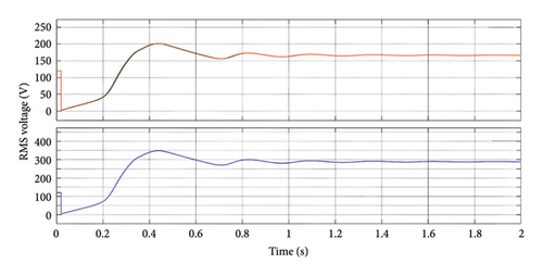
Figure 7 shows the line-to-phase output voltage of the converter’s output waveform, which converts the input 700V DC with a closed loop PI converter to 440 V DC and uses an inverter again to convert to AC, and a phase-to-line voltage of 230 V is maintained to get a constant output voltage.
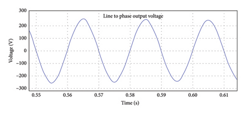
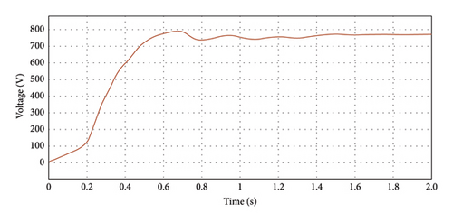
Figure 8 displays the output waveform of the inverter’s line-to-line output voltage, which is maintained by converting the converter’s 400 V DC output to a 400 V line-to-line AC output voltage. Figure 9 represents the output voltage waveform of the rectifier output, in which the WT driven by PMSG output is given to a three-phase full-wave rectifier, which converts the AC to 750 V DC, and it is maintained as output and given as input to the converter.

When comparing wind-driven PMSGs with pitch angle control with other types of WTs, there are a number of factors to take into account. PMSGs with pitch angle control as proposed can effectively operate under varying wind speeds. By adjusting the pitch angle, the turbine can maintain a constant rotational speed, ensuring efficient power generation across different wind conditions when compared with the existing system.
4. Conclusion
Without the aid of pitch control, PMSG-based variable-speed WECS was shown to be successful in varying its active power generation for a possible range of wind speeds. There is no requirement to feel the rotational speed in order for the Control method to operate regardless of changes in wind speed. The system’s efficiency is unaffected, and no more funding is needed. Pitch control is extremely sluggish, requires additional energy input, and results in severe wear and tear on hardware, whereas the system settles within limited cycles and is therefore very dynamic and quick-acting.
Hence, the control of PMSG parameters like voltage and frequency is done and simulated using MATLAB, and by the closed loop method, DC voltage, which is rectified using a three-phase diode rectifier, is regulated and controlled using a converter and controller and maintained at a constant voltage, and that DC voltage is again converted to AC voltage using a 3-Phase inverter to connect to the load in order to manage load demand. The same method can be applied in the future using micro-WTs, which even reduces the landscape and cost by paralleling more PMSGs so that all PMSGs contribute to load demand and efficiency can also be increased.
Nomenclature
-
- Cf
-
- Filter capacitance, μF
-
- f
-
- Frequency, Hz
-
- id, iq
-
- Generator current of the d-axis and q-axis, respectively, A
-
- KP
-
- Proportional constant
-
- KI
-
- Integral constant
-
- Ld, Lq
-
- Stator inductance of the d-axis and q-axis, respectively, A
-
- Rs
-
- Stator resistance of the generator, Ω
-
- Vdc
-
- Output voltage of the rectifier, V
-
- Vset
-
- Reference voltage, V
-
- vd, vq
-
- Generator voltage of the d-axis and q-axis, respectively, A
-
- Δv
-
- Ripple voltage
-
- ω
-
- Angular speed of the generator, rpm
Conflicts of Interest
The authors declare no conflicts of interest.
Funding
Authors declared that no funding was received for this Research and Publication. It was performed as a part of the Employment Hawassa University, Ethiopia.
Acknowledgements
The authors would like to thank the K.Ramakrishnan College of Technology, Samayapuram, Trichy, India, for their excellent support for the submission of their papers.
Open Research
Data Availability Statement
The data used to support the findings of this study are included in the article. Should further data or information be required, these are available from the corresponding author upon request.


