Enhancing the Rate Capability of Prussian Blue Analogs for Na-Ion Batteries: Key Factors and Control Strategies
Abstract
The open-framework structure of Prussian blue analogs (PBAs) allows the movement of alkali ions within the crystal, making PBAs promising electrode materials for high-rate sodium-ion batteries (SIBs). Typically, PBAs are synthesized in an aqueous environment through the instantaneous reaction of transition metal ions with ferrocyanide ions, resulting in the inclusion of water in the lattice and the induction of Fe vacancies. These defects decrease the rate capability of the synthesized material; therefore, the principles behind their formation must be comprehensively elucidated to maximize the performance of synthesized PBAs. This review describes various PBA synthesis methods and explores the principles behind defect formation in materials specific to each synthesis technique. Additionally, the mechanism through which crystal structure and morphology determine the rate capability of PBAs is discussed. This review also examines critical factors affecting kinetics and discusses strategies for improving rate capability and mitigating performance degradation. Elucidation of the changes in material parameters due to synthesis processes and conditions is crucial for increasing the rate capability of PBA materials.
Summary
- •
The versatility of PBAs as energy storage materials is underscored
- •
Critical properties impacting PBAs’ rate capability are discussed
- •
Various analyses of PBAs’ physicochemical and electrochemical properties are reviewed
- •
Synthesis strategies for PBA materials to improve rate capability are introduced
1. Introduction
Electrochemical energy storage devices, which convert chemical energy into electrical energy, are used in various applications because of their high thermodynamic conversion efficiency compared with other energy conversion devices [1, 2]. Lithium-ion batteries (LIBs), in particular, stand out because of their ability to shuttle lithium ions between electrodes, offering superior energy delivery performance [3, 4]. These batteries have low redox potential and exhibit excellent energy density and capacity, making them indispensable in various applications, from large-scale machinery to portable electronic devices [5–8]. Recently, the United Nations defined carbon neutrality by 2050 as the world’s primary goal to address climate change threats, calling for global cooperation [9]. This has led to a worldwide shift from internal combustion engine vehicles to electric vehicles, increasing the demand for LIBs [10]. However, lithium resources are geographically concentrated in South America, parts of Australia, and Asia, posing challenges to stable supply and giving rise to environmental concerns due to mining [11, 12]. Consequently, research on batteries using alkali ions with physical and chemical properties similar to those of lithium ions has become increasingly active.
Recent research has focused on the development of batteries based on sodium ions, which are abundant and relatively inexpensive, as an alternative to LIBs [13, 14]. Additionally, due to the low solvation energy of Na ions in electrolyte solvents, ion insertion at the electrolyte–electrode interface is enhanced [15, 16]. This enhanced ion insertion potentially results in higher power density. Moreover, Na+-based electrolytes have 10%–20% lower viscosity compared to Li+-based electrolytes, leading to higher ion conductivity [17–19]. Studies are underway to apply the typical cathode materials used in LIBs, such as layered oxides, spinel oxides, and olivine structure cathodes, in sodium-ion batteries (SIBs). However, because of the higher atomic mass and larger ionic radius of sodium compared to lithium, rapid ion diffusion is problematic in SIBs, leading to reduced output performance [20]. The higher redox potential of Na+/Na compared to Li+/Li results in a lower cell voltage, which contributes to the lower energy density of SIBs. In addition, the structural instability caused by the movement of larger sodium ions can result in a shorter lifespan. Metal–organic frameworks (MOFs) have a robust structure that maintains stability despite the movement of large ions [21]. Owing to their metal–organic linked open-framework structures, Prussian blue analogs (PBAs) have been extensively researched as electrode materials to enable faster and structurally stable movement of alkali ions than in other cathode materials.
PBAs form cubic crystal structures with octahedral units created by two transition metals linked by cyanide groups (−C≡N−), known as metal hexacyanometallates (M1[M2 (CN)6]) [22]. During electrode charge and discharge, alkali ions move in and out of the eight interstitial sites in the cubic lattice, enabling the storage and release of electric charge. The cubic open-framework structure of PBA accommodates large ions, making PBAs versatile cathode materials. They can reversibly host single-valent ions (Li+, Na+, K+, Rb+, and Cs+) and multivalent ions (Mg2+, Ca2+, Zn2+, and Al3+), as well as nonmetal charge carriers (H+, NH4+, and H3O+), potentially offering high energy density [23]. Depending on the redox activity of the two transition metals in PBA, either one or two redox reactions can occur within the stable potential range of the employed electrolyte among aqueous solvent, organic solvent, and ionic liquid. Typically, when Fe occupies the M1 site, chemical reactions involving both transition metals are induced, making metal hexacyanoferrates (M1[Fe(CN)6]) the most commonly used materials in these applications.
Metal hexacyanoferrates, formed by combining M1 cation and Fe(CN)6 anion, have extremely low solubility product constants (Ksp). When synthesized from an aqueous precursor solution, the crystal structure incorporates H2O molecules. Concurrently, this process creates empty Fe sites, leading to the formation of Fe vacancies, resulting in PBA with the chemical formula AxM1[Fe(CN)6]y∙wH2O. In this formula, “A” represents the alkali ion incorporated into the crystal post-synthesis, where 0 < x < 2, 0 < y < 1, and “w” signifies the amount of water in the crystal structure [24]. Water and Fe vacancies formed within the PBA hinder the movement of alkali ions within the crystal during charge and discharge, thereby reducing the rate capability. In addition, the insertion of Na into the structure during charge and discharge can twist the cubic crystal structure, leading to a transition to a different crystal structure. Such structural changes also affect the rate characteristics [25]. The effect of PBA material parameters (water-related defects and Fe vacancies) on the kinetics of Na ions must be elucidated to enhance the low-power performance of PBAs used as cathode materials in SIBs. Accordingly, the mechanisms governing these parameters should be clarified for the PBA electrode with high-rate capability.
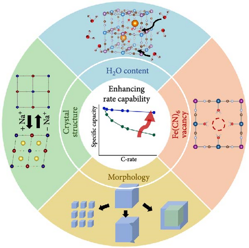
This review addresses strategies for synthesizing PBAs to improve their rate capability when used as electrode materials. Section 2 explores various PBA synthesis methods, examining how specific material parameters that reduce rate capability are generated. We also discuss how these defects can be reduced from the perspective of each synthesis method, offering a comprehensive understanding of the synthesis strategies for improving the rate capability of PBAs. In Section 3, we examine how the characteristics of the obtained material affect the kinetics of sodium ions in PBAs, focusing on factors such as water, Fe vacancies, structure, and morphology (Figure 1). We then discuss how rate capability may be enhanced by controlling these factors [26, 27]. Ultimately, this review aims to provide a pathway for improving the rate capability of PBAs as cathode materials for SIBs through elucidation of the mechanisms governing these material parameters during synthesis to enable their control.
2. Synthetic Routes to PBAs With Different Shapes and Their Property Evolution
PBAs can be synthesized using various methods, each resulting in different water content, number of Fe vacancies, structure, and morphology [28–30]. These physicochemical properties determine the electrochemical behavior of SIB cathodes. Therefore, elucidation of the synthesis principles and their effect on properties is crucial, mainly because these properties affect sodium-ion movement kinetics and electrode conductivity, thereby affecting the rate capability. This section introduces various PBA synthesis methods, explains the principles behind crystal lattice formation in each method, and discusses how the control of process conditions affects the performance of the material during charge and discharge. The shapes of synthesized PBAs are primarily classified into zero-dimensional (0D), one-dimensional (1D), and two-dimensional (2D) nanostructured PBAs. The 0D form, consisting of powder particles, is advantageous for the practical use of PBAs as electrode materials in batteries [31]. To fabricate electrodes, these powder particles are commonly composited with binders and conducting additives. However, the addition of these inactive materials reduces the specific capacity of the electrode. Thus, 1D nanostructured PBA is sometimes directly synthesized on substrates to fabricate binder-free electrodes [32].
2.1. 0D Nanostructured PBAs: Powder Shape
Powder-shaped PBAs, fine particles with a large surface area, are categorized as 0D nanostructured PBAs. The powder morphology offers some general advantages and limitations when fabricated into electrodes. The powder allows easy control over particle morphology, such as the preparation of hollow shells or composites with carbon materials. The small size of these particles shortens the ion diffusion path and reduces the charge transfer resistance in electrochemical reactions, contributing to high-rate capability [33]. However, the low atomic packing density of the crystal structure leads to a relatively low volumetric capacity [34]. Powder-type PBA with cubic morphology has a low tap density, implying low volumetric capacity. Therefore, engineering the shape of powder-type PBAs to attain a higher tap density than that of cubic particles is beneficial for increasing volumetric energy density [26, 34]. In electrode fabrication using powder-type active materials, PBA powder must be mixed with binders and conducting additives. These additives add weight and volume to the electrode without adding capacity, thus decreasing specific capacity. Related research efforts have focused on reducing the amount of these additives to the minimum necessary weight or explored the preparation of binder-free electrode materials to enhance performance [35, 36].
The practical advantages and disadvantages arise in the liquid-state synthesis process commonly used for producing PBA nanoparticles. However, due to the very low solubility product constants (Ksp) of PBAs, the mixing of precursor solutions in the synthesis of powder-type PBAs leads to immediate nucleation and crystal growth. This results in the formation of PBAs with irregular shapes and random aggregation, leading to the formation of defects and water inclusion, which can decrease ion mobility [37]. The mechanisms determining the reduction in rate capability due to defects are discussed in Section 3. Defect minimization has been attempted in multiple studies through process adjustments to enhance rate capability.
The formation of PBA crystallites is induced by the bonding of transition metal ions with ferrocyanide ions. This bonding occurs rapidly during the mixing of precursor solutions containing these ions; thus, control of the nucleation and growth rate of the formed particles is necessary [38]. Chelation agents are added during synthesis to decrease the nucleation rate. These agents initially bind with transition metal ions to form Mx+ citrate, followed by coprecipitation with ferrocyanide ions, forming complexes. The low dissociability of Mx+ citrate enables the slow release of transition metal ions, reducing water inclusion and nucleation rate [25, 39]. The addition of surfactants can also control particle generation and growth rate in PBA synthesis. Surfactants stabilize nanoparticles by forming weak coordination bonds with transition metal ions, thereby regulating nucleation rate [40, 41]. In addition, particle aggregation can accelerate particle growth; thus, dispersing precursor ions to minimize aggregation can also reduce the growth rate [42–44]. In addition to reducing defects, decreasing particle size facilitates the diffusion of alkali ions in the PBA lattice. Smaller particles have shorter ion path within PBAs, enabling the rapid movement of ions. Particle size can be reduced by controlling the bonding of precursor ions at lower temperatures and decreasing reaction time [45, 46]. Higher synthesis temperatures accelerate crystal growth, and longer reaction times result in larger particles. Thus, selecting appropriate reaction conditions is crucial for particle size reduction.
2.1.1. Coprecipitation Method
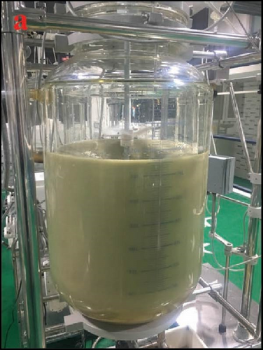
Coprecipitation involves mixing a solution containing transition metal Mx+ ions with a solution of Fe2+ or Fe3+ containing ferrocyanide or ferricyanide ligands (i.e., [Fe(CN)6]4− or [Fe(CN)6]3−) in various ways (dropping one solution into the other or simultaneously mixing both) to produce solid metal hexacyanoferrate (Figure 2a) [53–55]. The main advantages of this method are the low-cost precursors and low-temperature synthesis condition, eliminating the need for additional energy input, thus rendering it economical compared to other methods [26]. The process conditions, such as mixing speed, reaction temperature, solution pH, and precursor concentration, can be adjusted to control particle size, size distribution, morphology, and crystallinity [37, 56]. Although coprecipitation is commonly realized as a batch process, it may be set up as continuous production using reactors, making it highly scalable (Figure 2b). This allows for the transition from laboratory-scale synthesis to industrial-scale production [57]. These numerous advantages make coprecipitation a conventional and widely used method for the synthesis of PBAs [57, 58]. Unlike other methods, coprecipitation allows the production of PBAs containing transition metals other than Fe (Co, Ni, Mn, Cu, and Zn) by mixing two precursor solutions [55].
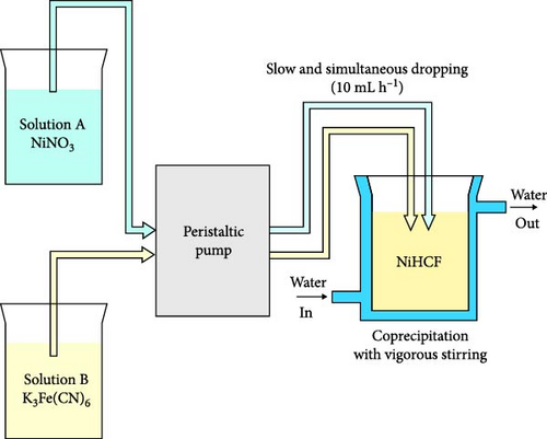
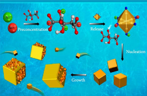


The coprecipitation method of PBA synthesis involves precipitate formation through a reaction between solutions containing two different transition metals (M1 = Co, Ni, Mn, Cu, Zn, or Fe). This process includes two stages: nuclei formation and growth of these nuclei into PBA particles. Because of the low solubility product constant (Ksp) of metal hexacyanoferrates, precipitation occurs instantaneously [58, 59]. The rapid reaction between metal ions Mx+ and ligands, leading to the formation of nuclei, results in the creation of numerous Fe vacancies and the incorporation of water coordinated to M1 within the PBA lattice [60, 61]. In the coprecipitation-synthesized PBA, water and Fe vacancies hinder the movement and insertion/extraction of alkali ions, thus affecting rate capability. To minimize these types of defects, the precipitation rate from precursor ions must be decreased (Figure 2c) [59, 62]. In addition, increased concentration of alkali ions in synthesis could prevent the probability of water binding and reduce related defects. This section describes approaches for altering coprecipitation process parameters to fabricate the PBAs capable of rapid ion insertion and extraction during charge and discharge.
First, the concentration of the precursor solution can be controlled to reduce the rate of coprecipitation from the precursor ions. High concentrations of precursor ions increase the probability of collisions, accelerating ion bonding. Conversely, low concentrations can result in sufficient product yield while necessitating significant synthesis time. Therefore, in the coprecipitation synthesis, the precursor concentration must be controlled to mitigate defect formation and ensure adequate synthesis yield [63].
The addition of chelating agents or surfactants to the precursor solution during synthesis can also decrease the rate of reaction between ions. These agents prevent the direct bonding of precursor ions, thereby slowing nuclei formation [39, 64, 65]. Furthermore, the concentration of guest ions (Na+ and K+) entering PBA’s interstitial sites may be increased to reduce defects formed during coprecipitation. Fe vacancies or water-related defects generated in coprecipitation hinder alkali-ion insertion and extraction. Thus, increasing the concentration of alkali guest ions such as Na+ in the precursor solution reduces the amount of coordinated water in the lattice, thus decreasing crystalline defects [66].
Finally, control of the particle growth rate involves adjusting the mixing time and reaction temperature of the two precursor solutions. Prolonged mixing time increases the probability of ion interaction, leading to larger particle size and potential aggregation, especially at high temperatures [46]. Larger particles feature a smaller contact area between the electrode material and electrolyte, thereby lowering the number of alkali ions involved in charge storage reactions [67]. Therefore, fine-tuning of the temperature and time of coprecipitation is crucial for synthesizing small particles. The impact of these coprecipitation process parameters on rate capability is discussed in detail in Section 3.
2.1.2. Solvothermal and Hydrothermal Methods
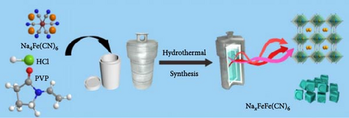
The hydrothermal method can employ a single precursor ferricyanide (AxFe(CN)6) dissolved in water. This approach restricts the synthesis to PBAs containing only one type of transition metal.
The high-temperature above 100°C and high-pressure conditions in an autoclave reactor enhance the solubility of precursor ions, thereby inducing greater number of interactions among precursor ions (Figure 2d). This leads to a greater number of interactions between the precursor ions, thus accelerating the nucleation of crystallites [74]. In addition, the high temperature reduces the precursor solution’s viscosity and water’s surface tension, facilitating ion mobility and favoring crystal growth [75, 76]. At elevated temperatures, evaporation may occur within the autoclave. This solvent evaporation could increase the liquid–air interface concentration of the solution, which possibly promotes crystal growth [77]. Increased pressure also increases the probability of ion collisions, accelerating crystal growth [69]. In hydrothermal synthesis, accelerated nucleation and increased growth rates can result in particles of uneven sizes with more defects within the material [78]. Thus, this method poses challenges in producing PBAs with high crystallinity and uniform particle size distribution. Similar to other methods, hydrothermal synthesis also requires control over the reaction rate of precursor ions and the growth rate of particles to minimize defect formation in the PBA lattice.
As mentioned above, solvothermal synthesis can induce more defects in the material than coprecipitation because of faster crystal nucleation and growth. Therefore, PBA with lower crystallinity is more likely obtained through the solvothermal method, necessitating the enhancement of crystallinity. To obtain high crystallinity and low defects through the hydrothermal method, the temperature in the autoclave and synthesis duration must be controlled [42, 79]. This section discusses approaches to adjusting these synthesis factors to produce PBAs with improved rate capability.
First, the solubility of the Fe(CN)6 precursor (AxFe(CN)6) can be controlled using the acidity of the solution. The acidity conditions that slow the dissolution of Fe2+ would inhibit the rapid nucleation of PBA crystals [40]. However, excessive acidity results in the rapid generation of Fe2+ in the reactor, leading to their swift recrystallization with residual Fe(CN)64−. Therefore, pH control may be employed to reduce Fe2+ solubility, thereby slowing the dissolution of transition metal ions and allowing the synthesis of PBAs with higher crystallinity [72].
Second, the introduction of organic solvents (e.g., isopropanol and ethanol) into the traditionally water-based solvent in the hydrothermal method can slow the precipitation of PBA particles from the precursor ions, increasing crystallinity [80–82]. The addition of organic solvents slows precipitation because of the reduction of solvent polarity. Thus, the addition of nonpolar organic solvents to polar H2O decreases the solubility of metal ions in the solvent, leading to a decrease in the rate of crystal formation [81].
Third, surfactant additives can assist in dispersing particles, reducing the nucleation and growth rates due to the extended distance between precursor ions. Thus, highly crystalline PBAs can be synthesized based on the decreased reaction rate [28]. Surfactants that selectively adsorb on specific crystal facets enable the control of particle shape and size by reducing surface energy and inhibiting further crystal growth. Furthermore, slow crystallization can be attained through the dispersion of particles in the precursor solution. For example, the solubility of precursors can be controlled by adding polymers or organic additives, which can regulate the reactivity between transition metals and Fe(CN)6 ions, slowing the dissolution of transition metal ions and decreasing the rate of precipitation [83, 84]. The effects of parameter control in the solvothermal and hydrothermal syntheses on rate capability are discussed in detail in Section 3.
2.1.3. Microemulsion Method
The coprecipitation and hydrothermal methods, which use water as a solvent, can incorporate water into the PBA lattice during synthesis. This inclusion of water can impair the electrochemical performance of PBAs, worsening the rate capability. To overcome this issue, a microemulsion method has been devised. The microemulsion method is expected to reduce the amount of water incorporated in the lattice through the formation of PBA particles within a confined space of micelles. Unlike the previously mentioned synthesis methods, this method does not require specialized and expensive equipment [85]. The microemulsion method employs a mixture of water and oil stabilized using a surfactant. Based on the characteristics of the surfactant (hydrophilic or hydrophobic), micelles are formed between water and oil, within which crystalline PBA particles are formed. This process minimizes the incorporation of water into the PBA lattice and enables control over the size and shape of the particles [86]. Moreover, this method is well suited for preparing uniformly sized particles because of the low reaction rate between particles [78].
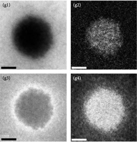
The microemulsion synthetic method is characterized by the presence of both aqueous and oil phases in the precursor solution. The form of this precursor solution changes depending on the properties of the surfactant. Depending on the functional groups of the surfactant, the droplets formed within the micelles can be either of water or of oil [87]. When oil droplets exist in a water medium, the system is called an oil-in-water system. Conversely, when water droplets are present in a continuous oil medium, the system is called a water-in-oil system, also termed reverse microemulsion (Figure 2e) [88]. PBAs are synthesized primarily via the reverse microemulsion method. The precursor ion dissolves exclusively in an aqueous solvent, thus confining the precursor ions to the water-filled spaces within small micelles [44, 89]. Subsequently, micelles containing transition metal ions combine with those containing Fe(CN)6 ions to form PBA crystallites [35, 89]. Critical conditions for PBA synthesis involve mixing oils such as cyclohexane and n-pentanol with an aqueous solution containing the ferrocyanide ligand (i.e., MxFe(CN)6). During this process, surfactants such as cetyltrimethylammonium bromide and isooctane promote the uniform dispersion of the ligands and metal ions in the water droplet interphase, thereby facilitating the formation of a stable microemulsion [44, 90].
A vital feature of the microemulsion method is the use of surfactants to form micelles of a consistent size, which in turn enables the synthesis of PBA crystallites of very uniform size. The size of the water droplets, or micelles, formed during the synthesis process determines the final PBA particle size. This particle size subsequently affects the electrochemical performance when the prepared PBA is used as an active electrode material [28]. The size of the micelles is determined by the water-to-surfactant molar ratio (w = [H2O]/surfactant), thus enabling the control over particle size during PBA synthesis through the adjustment of this molar ratio (Figure 2f) [89, 91]. However, in several studies, this synthesis method is claimed to be less predictable in determining particle size than other PBA synthesis methods.
The reverse microemulsion method uses surfactants to form nanoscale water droplets, ultimately yielding nanosized PBA particles [92]. The micelles generated during the synthesis must be thermodynamically stable in the solvent to form uniformly sized PBA particles. A stable dispersion system enhances micelle dispersion and promotes nanodroplet formation. This increase in dispersion increases the entropy of the system, spontaneously forming many nanodroplets and forming more uniformly sized particles [93]. Additionally, particle size control has been considered using the type and concentration of surfactants or auxiliary cosurfactants during the synthesis as mentioned above, surfactants must form a surface film and micelles with low interfacial tension. Thus, cosurfactants have been added to further decrease the interfacial tension [94]. Because of these properties, adjustment of the ratio of the two types of surfactants enables the control of micelle size, thereby facilitating the synthesis of particles with specific desired sizes (Figures 2f,g) [95].
In the PBA synthesis using the microemulsion method, surfactants and cosurfactants play crucial roles in controlling the micelle size and reducing the interfacial tension for improved micelle stability. However, their use introduces significant challenges, particularly in large-scale production. After synthesis, removing surfactants and cosurfactants from the final product requires extensive solvent washing, which can be a tedious and time-consuming process. Moreover, the possible residual impurities from these agents often make it difficult to obtain pure PBAs. As a result, this method may not be well-suited for large-scale manufacturing, where the presence of impurities and complex recovery processes can limit its practicality [78, 96].
2.2. Multidimensional Nanostructured PBAs: 1D Wire, Tube Shapes, and 2D Films
Section 2.2 summarizes the methods for synthesizing PBA with multidimensional structures, including wires, tubes, and films. PBAs with elongated structures such as wire- and tube-shaped forms are classified as 1D nanostructures, whereas film-shaped PBAs are categorized as 2D nanostructures. Both 1D and 2D structures are synthesized through electrodeposition. The advantage of 1D and 2D structures lies in the benefits derived from their morphology, which promotes fast ion transport [97, 98]. Furthermore, these structures exhibit excellent mechanical properties, offering high flexibility and resistance to volume expansion. In contrast, their morphology also presents particular challenges [99]. Their relatively low specific surface area can lead to reduced rate capability. Moreover, overpotential caused by uneven charge distribution and gas evolution on the electrode during charge/discharge is another issue that must be addressed [98].
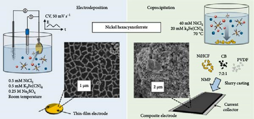
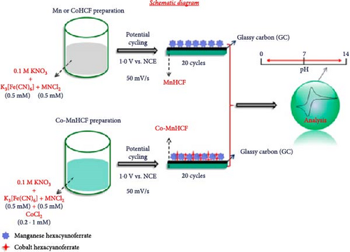
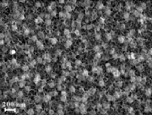
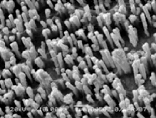
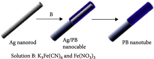
Conventional electrodeposition for producing 1D and 2D materials imparts practical advantages and disadvantages in synthesis. Directly depositing active materials onto a substrate allows binder-free electrode fabrication, simplifying the manufacturing process (Figure 3a) [99]. However, a significant challenge is the detachment of the film from the substrate after repeated electrochemical cycling in aqueous electrolytes [97, 99]. Coating a substrate with a polymer prior to PBA electrodeposition can improve adhesion between the PBA and the substrate, thereby addressing the peeling issue [103]. The surface roughness of an employed substrate can lead to uneven accumulation of PBA crystallite in the local areas, which increases electron transfer resistance. The increased resistance can cause nonuniform distribution and deposition of PBA crystals on the substrate [104]. To form a uniform electrode, surface treatment of the substrate can be performed to induce even formation of PBA crystallite. The experimental parameters for electrodeposition can be optimized to prevent excessive PBA accumulation [105–107].
2.2.1. Electrodeposition Method
Electrodeposition is a simple synthesis method that allows PBA to be synthesized directly on a substrate in a single step [108]. The PBA synthesis using electrodeposition is typically performed in a three-electrode cell configuration to precisely control the applied potential [109–111]. When a scanning voltage within a specific range is applied to a substrate immersed in a solution with transition metal cations and Fe(CN)6 anions using cyclic voltammetry (CV), PBA is deposited on the substrate [112]. The major factors determining the characteristics of 1D and 2D PBAs synthesized by the electrodeposition include the electrolyte concentration, electrolyte pH, the applied potential range, and the type of employed substrate [109]. Abbaspour et al. studied the potential range at which FeHCF deposition occurs by the electrodeposition from a single precursor source. They found that a specific potential range of −0.1 to +0.9 V is essential for the FeHCF synthesis, while a narrower voltage range of −0.1 to +0.6 V failed to assemble FeHCF [113]. Yang, Qian, and Deng [112] identified that a precursor solution with a specific pH is favorable for the FeHCF electrodeposition. They also found that the deposition rate on a gold substrate is faster compared to other substrates. According to Kumar, Joseph, and Phani [114], the fast deposition rate of gold is due to the catalytic effect of the substrate material.
Kumar et al. described the synthesis method for PBA films containing two transition metals (Co and Mn) (Figure 3b) [100]. They electrodeposited Co-MnHCF on a glass carbon substrate using a three-electrode system with a standard calomel electrode as the reference electrode and Pt foil as the counter electrode. The synthesized film was observed through field-emission scanning electron microscopy (FE-SEM) (Figure 3d).
Film, wire, and tube forms of 1D nanostructured PBA synthesized using this method may be densely grown on the electrode surface, as shown in Figure 3b,e. The active electrode material is directly deposited on the substrate; thus, it can be used as an electrode material without any additional electrode manufacturing processes.
In the electrodeposition, like other methods, the decreased rates of nucleation and growth of crystallites on the substrate can lead to the synthesis of high-crystallinity PBA. To reduce the nucleation rate, the electrolyte concentration must be controlled. A higher ion concentration can induce faster nucleation [117]. The pH and composition of the electrolyte can also alter the nucleation rate through the presence of specific ions [118]. Electrodeposition is typically carried out at low current densities and temperatures to retard crystal growth [119]. High current density leads to rapid growth of nuclei formed on the substrate, and rapid particle growth can reduce crystallinity; therefore, it is essential to use an optimized current density for electrodeposition. The loading amount of active material and film thickness can also alter the energy density and diffusion rate. PBA materials with high-rate capabilities can be developed by controlling these factors [99].
3. Factors Affecting the Rate Capabilities of PBA Electrodes
Here, “A” denotes an alkali cation, and “M” refers to a transition metal; “y” represents the ratio of Fe atoms in the PBA, and “w” signifies the amount of water in the structure. In the chemical reaction in Equation (9), the inserted alkali ions (A) are situated at the interstitial sites within the cubic lattice of the PBA. The resistance to ion transport to these sites is primarily determined by the H2O content and Fe vacancies within the crystal, as well as the crystal structure and morphology of the synthesized PBA. This section describes the effects of four physicochemical factors on the charge and discharge rate characteristics during ion transfer. The subsequent discussion focuses on synthesis strategies utilized to improve the rate capability characteristics of charging and discharging from the perspective of each factor.
3.1. H2O-Related Defects
As mentioned in Section 2, water molecules incorporated in PBA during synthesis exist in three forms: coordinated form bonded with transition metals inside the lattice, interstitial form located in the empty spaces between lattices, and adsorbed form (Figure 4a,b) [29]. This section elaborates on the mechanisms through which these types of water are formed during synthesis, followed by a discussion on how these water molecules affect the electrochemical characteristics of the formed PBA. Various methods for controlling the amount of water molecules in the lattice are further detailed.
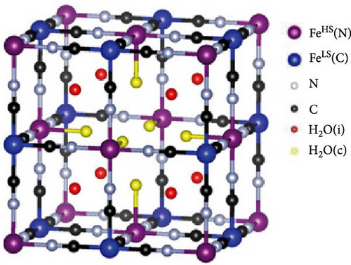
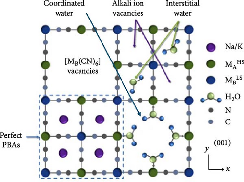
Coordinated water is rapidly formed during the formation of PBA when transition metal ions in an aqueous solution react with Fe(CN)6 anions. In the precursor solution of transition metals, H2O molecules are coordinated around the transition metal ions. When these coordinated transition metal ions encounter Fe(CN)6 ions, they quickly form a nucleus. In this process, coordinated H2O molecules are trapped within the lattice [49, 124]. Several authors have suggested that coordinated water is incorporated to counterbalance charges created by [Fe(CN)6]4− vacancies [59, 124, 125].
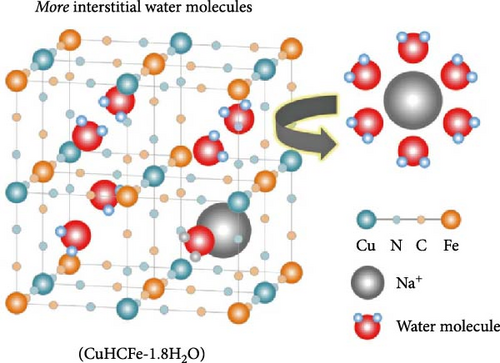
Interstitial water is formed when water molecules from the aqueous precursor solution are incorporated into the internal spaces of the lattice during the nucleation or growth of PBA crystallites, resulting in a structure where H2O is trapped within the interstices of the framework [126]. Unlike coordinated water, interstitial water is located at the center of the unit cell. Hence, there are eight potential insertion sites within the PBA lattice. Water molecules in these interstitial sites either exist independently or are connected to coordinated water via hydrogen bonds [127]. Interstitial water at position 8c occupies the space where alkali ions are inserted into the lattice, potentially impeding ion diffusion within the crystal [30, 127]. Lastly, adsorbed water refers to water physically adsorbed on the external surface of the PBA lattice. During the synthesis, moisture from the surrounding environment can adsorb in the pores of PBA crystals through hydrogen bonding [128, 129].
Coordinated and interstitial water in the PBA framework occupy pathways or storage sites for the insertion/extraction of alkali ions, thereby hindering ion insertion/extraction during charge and discharge [123, 130]. Interstitial water can trap inserted alkali ions during charge and discharge, forming hydrated ions and distorting the structure (Figure 4c) [126]. Furthermore, water and Fe(CN)6 vacancies within the structure disrupt the periodicity of the crystal. The reduced periodicity of the PBA framework can lead to lattice distortion or collapse during ion insertion/extraction, potentially decreasing the rate capability [131]. When PBAs are used as cathode materials in carbonate-based organic electrolytes, water in the lattice can promote electrolyte decomposition at a high working potential of the cathode. The electrolyte decomposition can lead to gas emissions such as HF, which deteriorate the electrode–electrolyte interface stability. Consequently, the decline in electrochemical performance can be accelerated [28]. Therefore, the amount of coordinated and interstitial water must be reduced to enable the rapid diffusion of alkali ions in PBA and ensure stability. At the same time, adsorbed water, which is located in the surface pores of the synthesized PBA particles, does not significantly affect the movement of ions inserted into the lattice. Because adsorbed water is weakly bonded to PBA crystals, it decomposes under high voltage [132]. Additionally, unlike coordinated and interstitial water, adsorbed water can be easily removed through vacuum drying. Hence, it has a smaller impact on the physicochemical properties of PBA materials [48].
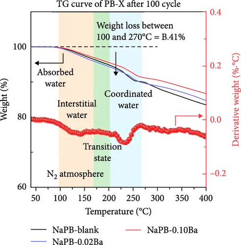
The open-framework structure facilitates rapid ion insertion and extraction, affording high-rate capability when used as cathode materials in SIBs. To ensure effective ion movement within the crystal, the amount of coordinated and interstitial H2O in the ion pathways and sites must be minimized [25]. The H2O types and contents within the structure can be identified and quantified by various experimental techniques [133]. The spectrum obtained from Fourier transform infrared spectroscopy (FT-IR) demonstrates the presence of H2O within the PBAs through the absorption peaks corresponding to the chemical bonding of H2O [134, 135]. X-ray photoelectron spectroscopy (XPS) analysis can distinguish different types of H2O present within the structure by examining the binding energy of the O 1s peak from H2O molecules. Since FT-IR and XPS analyses cannot quantitatively determine the amount of H2O types within the crystal, thermogravimetric analysis (TGA) is typically used to evaluate the content of different kinds of H2O quantitatively. The H2O amount within PBAs can be directly analyzed using 1H magic-angle spinning nuclear magnetic resonance (MAS NMR) spectroscopy [136, 137].
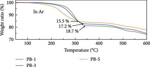
The H2O content in PBAs can be reduced through process and condition control during synthesis or postsynthesis treatment, thereby enhancing the rate capability [130, 138]. Physically absorbed water on the material’s surface is typically removed at around 100°C through thermal treatment in a vacuum or air [48, 139]. It is generally thought that both coordinated and interstitial types of water are removed at temperatures above 200°C [55, 129]. Various previous works performing TGA have reported different temperatures for the removal of different types of H2O (Figure 4d).
- 1.
Selection of type and concentration of guest ions in precursor
- 2.
Use of additives (chelating agents and surfactants)
- 3.
Adjustment of the coprecipitation conditions (pH and solvent)
- 4.
Postsynthesis treatment
3.1.1. Selection of Type and Concentration of Guest Ion
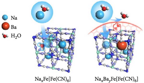
During the synthesis of PBA, alkaline ions from the precursor take a place in the interstitial sites of the lattice as a form of guest ions (A). The radius of the guest ion affects the space it occupies within the lattice. Therefore, the presence of larger ions can reduce the water content of the crystal [141, 142]. Liu et al. [123] added Ba2+ during coprecipitation and showed that intercalated Ba2+ ions prevent the influx of water into the interstitial sites of the lattice (Figure 5a). The insertion of Ba2+ provides additional structural support to the lattice, enhancing its strength and preventing potential structural distortions or collapses that can occur during charge and discharge. This approach enabled fast and reversible insertion and extraction of Na+ ions, achieving a high-rate capability (approximately 82.69%) for a 24-fold increase in discharge rate (6 C vs. 0.25 C). Zhou et al. [144] reported the larger radius of K+ ions compared to that of Na+ ions makes them suitable for occupying the vacant spaces within the MnHCF lattice. The research team synthesized KMnHCF by introducing K+ (1.38 Å) with a larger ion radius than Na+ (1.26 Å) during the synthesis to prevent the H2O inclusion into the lattice. As a result, they blocked the insertion of water into the vacant spaces, inducing shorter lattice constants and less distortions. This approach enhanced the structural stability of the MnHCF lattice, resulting in 79% rate capability for a 20-fold acceleration in discharge rate (20 C vs. 1 C).
During the synthesis of the PBA structure, the concentration of alkali ions in the precursor can be increased to reduce the amount of water. Additional alkali ions occupy vacant spaces in the lattice, thereby preventing water entry into these positions. Li et al. [70] reported that maintaining a high content of Na+ in the lattice reduces the amount of water in the lattice, resulting in the preservation of the reversible structure during cycling. The research team added NaCl during the synthesis process to achieve a Na-rich composition, ultimately obtaining Na1.56Fe[Fe(CN)6]∙3·1H2O with reduced water content (Figure 5b). This approach prevented the insertion of water into the lattice, contributing to the maintenance of structural stability during discharge, as evidenced by the absence of shifts in the X-ray diffraction (XRD) peaks of (200) and (400). The research team also measured the specific capacity at various current densities, confirming improved rate capability.
3.1.2. Use of Additives
When synthesizing PBAs using coprecipitation or hydrothermal methods, slowing down the nucleation and growth rates results in minimization of physical space within the PBA structure. This reduction in internal space within PBAs impedes the insertion of water molecules. Notably, the chelating agents or surfactants in the precursor solution can decelerate nucleation and growth rate of PBA, thereby reducing the amount of water in the synthesized PBA [37]. The chelating agents and surfactants in the solution bind to the transition metal ions and release those slowly, reducing the nucleation and growth rates. Furthermore, surfactants prevent the agglomeration of particles, maintaining particle separation during nucleation and growth, thus controlling the initial nucleation rate.
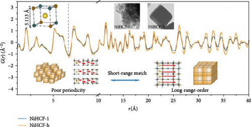
Wu et al. [145] slowed the crystallization of CoHCF through the addition of sodium citrate. In the presence of the chelating agent, Co2+ ions bonded with citrate rather than with water, forming Co citrate, enabling the gradual release of Co2+ ions. This strategy decreased the rate of coprecipitation reaction in an aqueous solution, thereby reducing the nucleation rate. As a result, Na1.85Co[Fe(CN)6]0.99∙2·5H2O with a lower water content in the lattice was obtained. Its rate capability showed above 50% for a 20-fold faster discharge rate (20 C vs. 1 C). Xu et al. [131] reduced the water content of NiHCF by adding Na4P2O7 as a chelating agent during synthesis. They obtained Na0.22Ni[Fe(CN)6]0.76∙3·67H2O, producing highly crystalline NiHCF with reduced water content. Figure 5c presents the pair distribution function (PDF) curve of NiHCF-l and NiHCF-h. A higher intensity in the PDF corresponds to greater periodicity. The NiHCF-h sample exhibited higher periodicity at longer distances than the NiHCF-l sample due to the higher crystallinity from the reduced amount of water. This reduction in water content facilitated the movement of Na ions resulting in the rate capabiltiy of over 82% for a 25-fold increase in discharge rate (5 C vs. 0.2 C) (Figure 5c). Park et al. [146] introduced a surfactant (polyvinylpyrrolidone [PVP]) to weaken the electrostatic interactions between CN ligands and water molecules, thereby preventing the incorporation of water. Owing to the polarity of PVP, the hydrophilic part attracted water molecules, whereas the hydrophobic part repelled them, indirectly regulating the electrostatic forces between CN ligands and water molecules and preventing the entry of water molecules during the formation of Mn-Co-PBA@CF crystals. The obtained material showed a high-rate capability, 69% for a 10-fold increase in discharge current density (1 vs. 0.1 A g−1).
3.1.3. Adjustment in pH and Concentration of Precursor Solution
You et al. [138] synthesized FeHCF by hydrothermal method in an acidic environment to reduce the nucleation rate, ultimately decreasing the amount of water in the lattice. In an acidic environment, Fe(CN)64− slowly decomposes into Fe2+, and during the process, part of Fe2+ is oxidized to Fe3+. The reaction between Fe3+ and [Fe(CN)6]4− resulted in a slow growth of the product, leading to the synthesis of highly crystalline HQ-NaFe with fewer vacancies and a composition of Na0.61Fe[Fe(CN)6]0.94. In contrast, a sample synthesized under constant pH conditions, LQ-NaFe with more vacancies and a composition of Na0.13Fe[Fe(CN)6]0.68, exhibited a specific capacity of 110 at 150 mA g−1. For LQ-NaFe, no discharge capacity was observed at a higher current density of 600 mA g−1, indicating a 0% rate capability. Conversely, HQ-NaFe demonstrated an improved rate capability of approximately 64% with a fourfold increase in discharge rate (600 vs. 150 mA g−1).
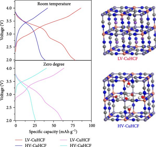
Wang et al. [143] used ethanol as a solvent in the coprecipitation of CuHCF to prevent direct bonding between Cu2+ ions and water. This approach aimed to reduce the amount of water incorporated in the lattice. By partially substituting the water solvent in precursor solution with ethanol, low-water-content CuHCF (LV-CuHCF) with a Fe/Cu ratio of 0.931 was synthesized (Figure 5d). LV-CuHCF exhibited a enhanced rate capability than HV-CuHCF (68% vs. 40%) at a 50-fold increase in discharge rate (50 C vs. 1 C). This was attributed to the lower content of coordinated water in LV-CuHCF, which was synthesized by partially replacing water with ethanol.
3.1.4. Postsynthesis Treatment
The two distinct types of water in the PBA lattice have been identified, both of which are removed at temperatures exceeding 200°C. Although the amount of incorporated water may be reduced using certain methods during synthesis, the water content in the lattice may be reduced through heat treatment. Wang et al. [48] annealed FeHCF at 270°C to remove incorporated water, obtaining Na1.76FeFe(CN)6∙2·5H2O. This process minimized the water content within the structure and led to high rate capability at various current densities.
3.2. Fe Vacancies (Fe(CN)6 Vacancy)
Fe vacancies are formed during the rapid coprecipitation of transition metal ions and Fe(CN)64− ions, where transition metals may fail to bond to ferrocyanide ions (Figure 6a). The empty site at Fe atom position can be formed within the crystal structure [29]. These voids are filled by coordinated water molecules, indicating a deficiency or defect in the [Fe(CN)6]4− lattice [28, 148]. As mentioned in Section 3.1, when transition metals (M) coordinate with water within the PBA structure, direct bonding between M and Fe via cyanide (–CN–) becomes impossible. Therefore, the formation of coordinated water leads to the generation of vacancies at Fe sites. The structural instability resulting from forming Fe vacancies hinders the movement of alkali ions within the lattice and impairs their insertion and extraction. Therefore, the quantity of Fe vacancies within the PBA structure must be minimized. The controlling Fe vacancies could be done by controlling rapid crystallization kinetics through different parameters such as synthesis temperature, pH, and concentration of the precursor solution [109].
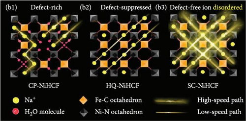
The electric charge storage in PBAs involves redox reactions of Fe or transition metals. The vacancies generated at the Fe sites reduce the active charging sites where these reactions occur, thus decreasing the nonelectrochemical capacity [30]. This reduction may exceed 10%, thereby complicating the achievement of theoretical capacity in PBA materials [92]. Furthermore, these vacancies can disrupt the pathways for electron movement within the material, thus impairing electrical conductivity [149]. Finally, based on the principle of electric neutrality, positively charged Fe vacancies reduce the overall positive charge of the structure, leading to a decrease in the concentration of alkali ions and, subsequently, a reduction in capacity [28].
Fe vacancies also decelerate the diffusion of ions within the PBAs. Besides, the generation of Fe vacancies within the PBA framework disrupts the continuity of Fe-CN-M bonds, leading to unstable structure (Figure 6b). This compromised bonding weakens the mechanical strength of the PBA structure. The structure may deteriorate during repetitive insertion and extraction of alkali ions during charge and discharge. Structural degradation reduces the charge storage capacity and lifespan based on capacity fading during cycling; additionally, the collapsed structure can obstruct ion pathways, leading to reduced rate capability [24, 66]. Furthermore, the collapsed structure disrupts the continuous pathways for electron conduction within the lattice, potentially reducing electrical conductivity. Reduced electrical conductivity in PBAs decreases the speed of ion movement [150]. Therefore, minimizing Fe vacancies within the lattice is essential for enhancing the capacity and achieving high-rate capability in PBAs.
- 1.
Introduction of dopants into the precursors, thereby inhibiting the coordination of H2O
- 2.
Addition of additives (chelating agents and surfactants) in the precursor to induce the gradual release of transition metal ions, enhancing crystallinity
- 3.
Adjustment of the coprecipitation reaction condition (pH, solvent type, and temperature)
3.2.1. Introduction of Dopants to the Precursors
FeHCF possesses two distinct oxidation states of iron (Fe2+ and Fe3+) coordinated with C and N, unlike other PBAs. The high-spin Fe (FeHS; Fe3+) predominantly contributes to redox reactions, whereas low-spin Fe (FeLS; Fe2+) only partially participates in [153]. The substitution of Zn dopants at FeHS sites has been reported to reduce Fe vacancies, accordingly enhancing the rate capability [154]. This rate capability enhancement is attributable to the replacement of coordinated water molecules at the FeHS sites by dopant. The Zn substitution in FeHS sites leads to a decrease in water content and consequently a reduction in Fe vacancies. A dopant can be introduced into the transition metal site in PBA using precursor solution including a doping element in coprecipitation synthesis [155].
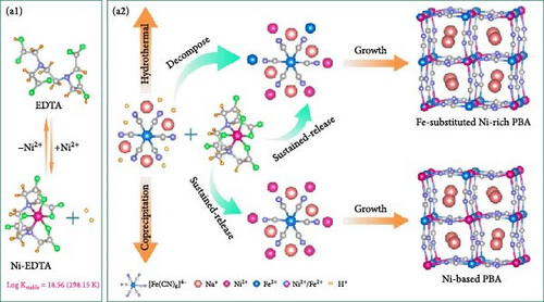
Shen et al. used Ni as a dopant at Fe sites and added the chelating agent ethylenediaminetetraacetic acid (EDTA) to reduce Fe vacancies in the prepared material and enable it to maintain structural stability during charge and discharge (Figure 7a) [151]. When Ni is doped into FeHCF, Ni2+ replaces Fe3+. The substitution of Fe3+ with inactive transition metal inhibits the formation of coordinated water and consequently Fe vacancies. This approach resulted in a reduction in the content of coordinated water. The doping of a FeHCF sample (H-PBA) with Ni yielded Na1.59Ni0.65Fe0.35[Fe(CN)6]0.97·2·28H2O with a Fe vacancy content reduced by approximately 6%. Through this approach, they secured the Na+ migration pathways, significantly increasing rate capability, to approximately 78% for a 50-fold discharge acceleration (500 vs. 10 mA g−1).
3.2.2. Use of Additives
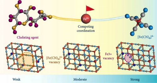
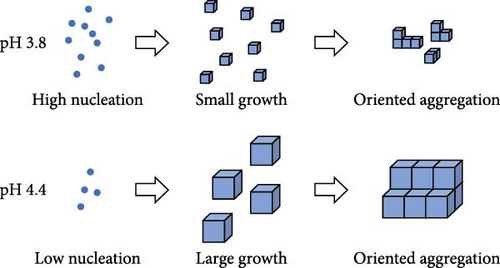
Section 3.1 discussed the addition of chelating agents and surfactants during the synthesis of PBA to reduce the H2O content as was discussed. Fe vacancies are generated owing to the rapid nucleation and growth of PBA, necessitating control over the reaction kinetics. Therefore, chelating agents and surfactants minimizes coordinated water within the PBA, thereby reducing Fe vacancies (Figure 7b).
Xu et al. [152] induced slow crystallization during the coprecipitation synthesis of NiHCF by adding Na4P2O7 as a chelating agent. Ni2+ chelates with P2O74−, preventing Ni2+ from bonding with water and causing the slow release of Ni2+. This approach slowed the coprecipitation reaction in the aqueous solution, thus reducing the amount of coordinated water. As a result, the prepared PBA maintained its structure even after multiple charge–discharge cycles, resulting in a significantly improved rate capability, 78% rate capability for a 50-fold faster discharge rate (50 C vs. 1 C).
3.2.3. Adjustment of the Coprecipitation Reaction Conditions
- 1.
The reduction of Fe vacancies through solvent control is achieved by substituting water with an organic solvent. PBAs are synthesized through hydrothermal coprecipitation in aqueous solutions, which can lead to the generation of coordinated H2O during synthesis. However, the use of solvothermal methods, with organic solvents instead of water, can reduce coordinated water. As mentioned above, the formation of coordinated water creates vacancies within the lattice, leading to the generation of Fe vacancies. Therefore, reducing the amount of incorporated water can decrease the number of Fe vacancies.
- 2.
The nucleation and growth of PBAs can be slowed by controlling synthesis temperature, thus reducing the amount of lattice water incorporated during synthesis and minimizing Fe vacancies. Synthesizing PBAs at the appropriate temperature for each material can result in more stable crystal growth, thus inhibiting the formation of Fe vacancies.
- 3.
The adjustment of pH may be used to change the ratio of Fe2+ to Fe3+ in synthesizing FeHCF. Changes in the concentration of H+ ions affect the quantities of Fe2+ and FeFe(CN)62− present during FeHCF synthesis (Equations (10) and (11)) [138, 157]. In acid environment, the precursor Fe(CN)6 can rapidly dissociated Fe2+ which reacts with Fe(CN)64– to form FeFe(CN)62-. Therefore, acid decomposition decelerates the nucleation and grain growth rate in general, resulting in the lattice with fewer Fe vacancies [58]:
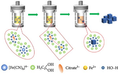
Wang et al. [82] have performed the synthesis using the solvothermal method with ethylene glycol as the solvent to eliminate water incorporation and reduce the reaction rate. Ethylene glycol hinders the interactions between Fe2+ and [Fe(CN)6]4−, serving as an insulator layer and preventing oxidation. The role of the insulator layer is to slow the formation of FeHCF crystals, thereby reducing the number of Fe vacancies and enabling the synthesis of a stable crystal structure (Figure 7c). The M-PB, synthesized with the least amount of Fe vacancies, exhibited an approximately 50% rate capability for an 80-fold increase in discharge current density (4000 vs. 50 mA g−1). Yang et al. [150] reported that a decrease in the crystal growth rate diminishes Fe vacancies at low temperatures. This research team aimed to determine the optimal temperature at which Fe vacancies are minimized by conducting coprecipitation synthesis at various temperatures (0, 40, and 80°C). With the increase in synthesis temperature, the growth of PBA crystals accelerates, generating more Fe vacancies. Therefore, sample (Na1.73Fe[Fe(CN)6]0.98 0.02) synthesized at the lowest temperature contained less Fe vacancies than that (Na1.12Fe[Fe(CN)6]0.92 0.08) at the highest temperature, exhibiting an around 71% improvement in rate capability when discharged at a much higher rate (8 C vs. 0.1 C).
Li et al. [157] decreased synthesis pH by adjusting the amount of HCl, which determines the pH of the hydrothermal solution and a material with fewer vacancies. The decrease in pH, as described by Equation (10), promotes the formation of Fe2+ and stabilizes them because Fe2+ ions are more stable in an acidic environment, which prevents easy oxidation to Fe3+. Ultraviolet-visible spectroscopy, which measures a sample’s light absorbance in the ultraviolet and visible ranges, was employed to analyze the oxidation state of Fe in the FeHCF. Neale et al. reported that the change in absorbance peak at 700 nm indicates charge transfer between low-spin Fe2+ and high-spin Fe3+. This peak decreased when the FeHCF sample was prepared from a higher pH precursor solution, suggesting a higher concentration of high-spin Fe2+ in its reduced form. In addition, at lower pH levels, the reaction rate decreases (Figure 7d). The reduction in Fe vacancies attained through this strategy improved the stability of the prepared PBA material by preventing structural changes during K+ insertion and extraction. This reduction in Fe vacancies resulted in a 29% improvement in rate capability for a 120-fold increase in discharge current density (9000 vs. 75 mA g−1).
3.3. Crystal Structure
Metal hexacyanoferrates synthesized via various methods in previous studies primarily have cubic structure (). In this structure, transition metal M is connected to N in the C≡N groups of the PBA framework, whereas Fe is connected to C atoms. In other words, octahedra consisting of MN6 and FeC6 units are continuously linked to form a cubic structure. Specifically, in the case of FeHCF, Fe is divided on the basis of its spin state into a structure combining high-spin FeN6 and low-spin FeC6 units [58, 60]. The oxidation state and spin state of the transition metals in PBAs can be analyzed based on the X-ray absorption near edge spectroscopy (XANES) with X-ray irradiation. The peak shift to a higher energy range in the XANES spectrum can identify an increase in the oxidation state of transition metals. For instance, Pham et al. [158] analyzed the changes in the oxidation state and spin state of Fe and Mn during the charge and discharge of MnHCF using operando XANES. Mansour et al. [159] examined the oxidation state of Fe in crystals synthesized using different precursors for FeHCF through XANES analysis.
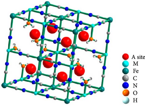
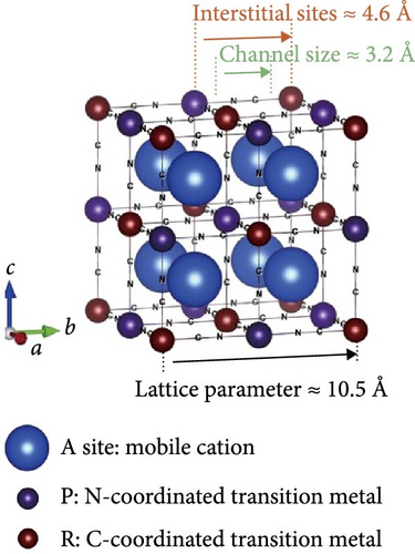
Cubic structured PBAs have a rigid open framework that includes a sufficiently large interstitial “A” site (≈4.6 Å diameter) capable of accommodating large alkali ions and wide channels (3.2 Å, <100> direction; Figure 8a) [24]. Therefore, from a crystal structure perspective, its excellent rate capabilities for charge and discharge were attributed to the rapid insertion and extraction of alkali ions. At the same time, the structure of PBA can vary depending on the concentration of alkali ions (A) denoted by “x”; the amount of Fe(CN)6 vacancies (y), as explained in Section 3.1; and the quantity of coordinated interstitial water within the lattice (w), as defined by the following formula: AxM[Fe(CN)6]y∙wH2O. In other words, the PBA structure can change based on these factors [127]. Generally, PBA exhibits a cubic structure when the alkali-ion (x) concentration is low ( = deficient). In contrast, alkali-rich (x > 1) PBA materials tend to form monoclinic (P21/n) or rhombohedral () structures, as shown in Figure 8b [37, 56].
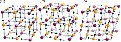
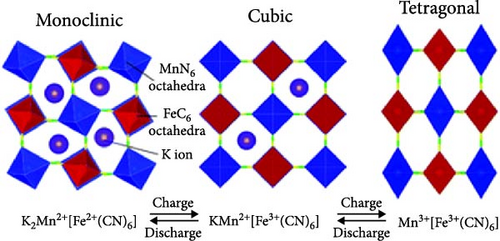
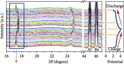

A study analyzing structural changes during charge and discharge through density functional theory (DFT) calculations demonstrated that the rhombohedral structure is more stable than the cubic structure when alkali ions are inserted (sodiated), leading to phase transitions [164]. Changes in the PBA structure occurring during charge, discharge, or afterward can be elucidated through various analysis methods beyond XRD. Raman analysis may be used to gain insights into the reversible phase transition procedures, revealing the overall structural changes in the material. Local structures within the material can be investigated using X-ray absorption spectroscopy, X-ray absorption near edge structure, and extended X-ray absorption fine structure analyses [28]. PBA undergoes phase transitions during charge and discharge, which can induce lattice deformation and potentially reduce mechanical stability [34].
- 1.
Addition of dopants to induce a stable phase, mitigating structural distortions during charge and discharge
- 2.
Addition of chelating agents and surfactants to increase the PBA crystallinity or synthesize stable PBA phase with increased alkali-ion contents
- 3.
Control of the synthesis temperature to reduce the H2O content and Fe vacancies within the lattice, resulting in high crystallinity
3.3.1. Addition of Dopant
Partial substitution of the transition metal sites in PBA through doping can be used to control the structure of PBA. Dopants are selected based on the bond characteristics of the transition metal (bond length and coordination number). Doping reduces the bandgap of the synthesized PBA, induces transitions to stable phases, and alleviates structural distortions during charge–discharge processes, allowing rapid ion diffusion.
Quan et al. [169] used a coprecipitation synthesis method to induce a phase transition from cubic to a more stable monoclinic structure in CoHCF (Na2CoFe(CN)6) via doping with Ni. They explained that Ni-doping altered the lengths of bonds between atoms, leading to the phase transition from cubic to monoclinic (Figure 9a). Furthermore, doping contributed to electron transfer, reducing the band gap from 1.1 to 0.81 eV. Their DFT calculations indicated that the introduction of external electrons by Ni ions improved charge transfer. The reduced band gap and improved charge transfer in their turn increased the electrical conductivity. In addition, the transformation into a more stable monoclinic structure minimized structural distortions occurring during ion insertion and extraction, allowing for a 72% improvement in rate capability at a significantly faster rate (1000 vs. 20 mA g−1).
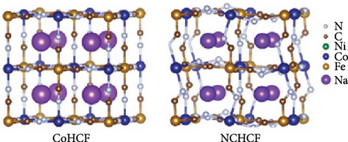

Kim et al. [171] achieved a high-rate capability by doping CoHCF with Zn at the Co site, thereby reducing structural distortions occurring during charge and discharge. In the CoHCF structure, Co is weakly bonded to N in the CN group, leading to the dissolution of Co due to structural distortion during charge and discharge. The added Zn is connected to six Fe atoms and CN groups in CoHCF, bonding with four neighboring Fe atoms (Figure 9b). Zn-doping reduced the lattice parameter, and the interaxial angle approached 90°. The substitution of 0.07 Co with Zn alleviated structural distortion during charge and discharge, suppressing Co dissolution. They reported an ~81% rate capability improvement when the charging rate was increased by 20-fold (2.0 vs. 0.1 A g−1).
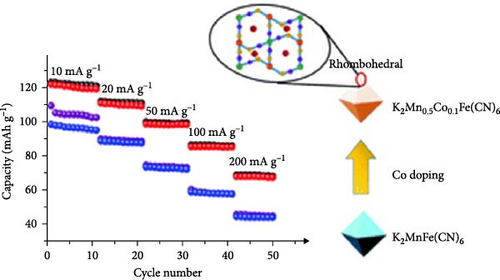
Jiang et al. [173] reduced the structural distortions caused by Mn3+ in MnHCF by doping Fe into Mn sites. During charge and discharge, MnHCF undergoes structural distortion due to the Jahn–Teller effect caused by the generation of Mn3+, resulting in a transition from a monoclinic to a tetragonal structure [164]. DFT calculations showed that doping Fe into Mn sites reduced the density of Mn3+. In addition, Fe doping reduced the band gap from 3.8 to 2.7 eV, reducing the activation energy of ion diffusion and increasing ion conductivity, which induced a phase transition from the tetragonal phase to a less structurally distorted monoclinic phase during charge/discharge. It reduced structural distortion during charge and discharge, enabling rapid ion insertion and extraction, resulting in ~63% rate capability for a 12-fold increase in discharge rate (120 C vs. 10 C). Jiang’s research team also doped Co into the Mn sites of MnHCF, resulting in an improvement in rate capability through a phase transition to a less distorted rhombohedral structure (Figure 9c) [172].
The high-entropy strategy can be employed to achieve the stable PBA electrode [174–176]. The high-entropy material typically involves mixing five or more elements in equimolar ratios to produce fewer phase alloys for a stable material based on the increased configurational entropy [177]. In synthesizing PBAs from aqueous precursors, the inclusion of H2O-related defects and Fe vacancies within PBAs would induce structural instability during Na-ion insertion/extraction, potentially degrading stability and rate capability. High-entropy PBAs maintain a single phase during charge and discharge reaction, allowing Na-ion transport via a solid-solution mechanism. No phase transition in the storage mechanism results in stable charging and discharging behavior [175]. Ma et al. manufactured a stable PBA by incorporating five metal cations at a high-spin nitrogen-coordinated site, which undergoes charging and discharging through a phase transition-free solid-solution phase, achieving near zero-strain.
3.3.2. Addition of Additives
The addition of an alkali-ion-containing chelating agent in the PBA synthesis via coprecipitation can increase the concentration of alkali ions within the PBA crystals, inducing a stable rhombohedral or monoclinic structure. Rhombohedral and monoclinic structures have lower band gaps and energy barriers for alkali-ion insertion than cubic structures. In addition, these structures allow reversible phase transitions during charge and discharge, thereby reducing mechanical stress and enhancing rate capability [25, 139].
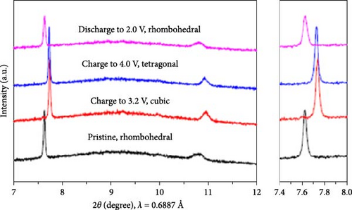
Wang et al. [168] added sodium citrate as a chelating agent during the coprecipitation of FeHCF, which elevated the sodium ions contents within the prepared FeHCF. This high sodium contents enabled reversible phase transitions between the rhombohedral, cubic, and tetragonal structures of PBAs during charge and discharge (Figure 9d). Furthermore, the elevated concentration of sodium ion within the lattice led to the formation of a rhombohedral structure. This high sodium ion resulted in reduced water content in the PBA, which may enhance the rate capability. In addition, the rhombohedral structure, known for its ability to facilitate rapid ion diffusion, exhibited a high sodium-ion diffusion coefficient. As a result, when sodium content in the structure reached 1.73 through citrate addition, the product exhibited a rhombohedral structure, which was effectively restored during charge and discharge. Owing to the reversible maintenance of the structure, the synthesized PBA showed a rate capability of 83% for a 50-fold increase in discharge rate (500 vs. 10 mA g−1).
The incorporation of a chelating agent during coprecipitation has been reported to slow the release of transition metal ions. This sluggish ion release minimizes the formation of vacancies and coordinated water in the crystal, enhancing the structure’s periodicity and stability [33, 178]. The structure with increased crystallinity maintained ion pathways during charge/discharge, enabling high-rate capability [130]. Jiang et al. [39] used sodium carboxymethylcellulose (CMC), commonly used as a binder, as a chelating agent in the coprecipitation PBA synthesis. According to DFT calculations, the bonds with CMC (binding energy: −4.39 eV) are more robust than those with citrate (bonding energy: −3.69 eV). As a result, CMC formed strong bonds with Fe3+ ions, causing a slow release of Fe3+. This, in turn, reduced the binding rate with Fe(CN)6 ions, slowing crystal nucleation and growth and further inhibiting Fe vacancy formation. The reduction in Fe vacancies maintain high crystallinity and allowed the structure to remain reversible during ion insertion and extraction. Consequently, the prepared PBA showed a rate capability of 78.5% for a 100-fold increase in discharge rate (1 C vs. 0.01 C).
3.3.3. Control of Synthesis Conditions (Temperature)
During coprecipitation synthesis, particle nucleation and growth rates may be controlled using reaction temperature. In other words, higher synthesis temperatures not only favor particle growth but also lead to faster crystal growth. Therefore, it is essential to conduct synthesis under appropriate temperature conditions.
Xie et al. [170] explained that during the coprecipitation synthesis of NiHCF at 0°C or 25°C, a rhombohedral structure may be obtained because of the reduced nucleation and growth rates of crystals. Synthesis at lower temperatures has a similar effect to the addition of chelating agents, slowing crystal growth and inhibiting the generation of Fe vacancies and incorporation of water. The reduction of these types of defects was accompanied by an increase in Na content within the lattice, leading to the formation of a stable rhombohedral structure. NiHCF synthesized at lower temperatures exhibited a structure with minor lattice distortion, allowing it to maintain a reversible rhombohedral–cubic structure during charge and discharge. Rhombohedral NiHCF (Na1.3Ni[Fe(CN)6]0.81) exhibited a rate capability of 78% for a 200-fold increase in discharge rate (40 C vs. 0.2 C).
3.4. Morphology
In the synthesis of PBA powder in an aqueous environment, the rapid binding of transition metal ions and Fe(CN)6 ions leads to the immediate formation of crystal nuclei and aggregation of irregularly shaped particles to form PBA [29, 152]. The aggregation of irregularly shaped particles results in stacking and forming larger particles. This reduces the interfacial area between the electrode material and the electrolyte, limiting the rates of ion insertion and extraction and consequently impairing the rate capability [44, 179]. Therefore, rate capability may be improved through the control of the nucleation and growth rates of particles, forming uniform, small-sized cubic-shaped particles [180]. In the case of FeHCF, the morphology of crystals varies depending on the ratio of growth rates along the (111) and (100) directions during crystal nucleation and growth. The facets of cubic FeHCF are oriented along the (100) plane [181, 182]. Consequently, cube-shaped FeHCF exhibits smooth alkali-ion insertion and extraction through the exposed (100) plane, resulting in good rate capability [183]. However, cube-shaped PBAs with a solid interior have limitations regarding their rate capability due to the extended diffusion path of alkali ions [184]. Consequently, numerous morphological engineering studies are being conducted to facilitate ion diffusion by assembling advantageous forms for the promoted ion diffusion, like core–shell or hollow shell structures [127].
The size and shape of PBA particles affect the rates of alkali-ion insertion and extraction because these characteristics determine the ion diffusion path and the interfacial area of electrode–electrolyte. A decrease in particle size increases rate capability by reducing the diffusion distance of ions within the crystal [26]. In addition, smaller particles extend the contact area between the electrolyte and electrode, reducing the interfacial impedance (Rct) and enabling rapid ion insertion and extraction [185]. The shape of PBA particles may also be designed to facilitate the movement of ions at the electrode surface in the electrolyte. As mentioned above, cubic particles exert considerable resistance to ion diffusion toward the interior upon electrode penetration, leading to decreased rate capability [34]. Therefore, the fabrication of particles with a morphology favorable for rapid ion insertion and extraction is necessary to improve the output performance. Furthermore, morphological engineering is required to minimize the structural strain generated at the electrode during charge and discharge. The volume of particles undergoes repeated changes by the insertion and extraction of ions; thus, the reducing particle size enhances structural stability and elevates rate capability. Consequently, the electrode composed of smaller particles becomes suitable for a stable electrode, particularly at high-rate condition [186].
- 1.
Reduction in the particle size for extended insertion sites and short ion path
- 2.
Fabrication of unique structures (hollow shell and core–shell) for reduced ion path and minimized volume change
- 3.
Etching particle for expanded electrode/electrolyte interface and additional ion pathway
3.4.1. Reducing Particle Size
Smaller particles have a greater specific surface area than larger particles, increasing the area of the interface between the electrode and the electrolyte. As a result, more active sites are available for the intercalation/deintercalation of alkali ions. Furthermore, the expanded contact area between the electrolyte and the PBA electrode reduces Rct, allowing more ions to participate in the charge–discharge reactions [67].
Kim et al. [187] reduced the size of CoHCF particles by synthesizing them at low temperatures. During coprecipitation synthesis, increasing the precursor precipitation temperature accelerates nuclei growth, forming larger particles. Conversely, a low process temperature favors nucleus generation over growth, resulting in smaller particles (Figure 10a). These smaller particles are believed to provide shorter diffusion pathways for the inserted alkali ions. Rapid insertion/deinsertion of Na+ ions in these tiny particles results in high-rate capability, 89% for a 20-fold increase in discharge rate (2 vs. 0.1 A g−1).

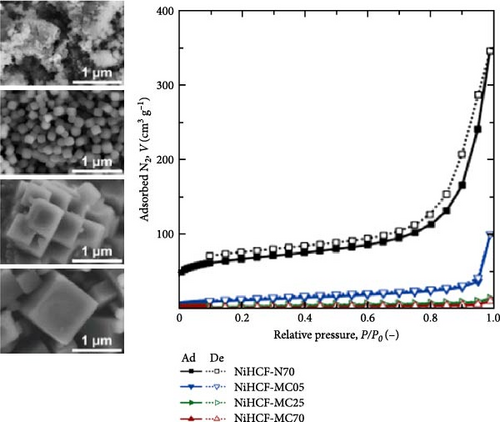
Park et al. synthesized various NiHCF samples through coprecipitation at various temperature conditions (5–70°C) similar to CoHCF fabrication; smaller particles were produced when synthesized at 5°C. This material showed a 79% rate capability for a 100-fold increase in discharge rate (100 C vs. 1 C) [45]. In contrast, the material synthesized at 70°C showed a rate capability of only 48% under the same conditions (Figure 10b).
Choi et al. [46] reduced particle size by decreasing the mixing time of the precursor solution and decreasing the concentration of the chelating agent. They also compared the effects of these changes on electrochemical performance [46]. The decrease in the mixing time of the precursor from 12 h to direct mixing shortens the growth duration, resulting in a reduced average particle size. Similarly, a decrease in the concentration of the chelating agent from 0.1 to 0.03 M increases the nucleation rate, inducing smaller particles. These adjusted synthesis conditions resulted in a decrease in particle size, shortening the path for alkali ions within the particles and increasing the rate capability.
At the same time, the reduced citrate-ion concentration in synthesis resulted in a higher possibility of transition metal ions binding with H2O, leading to the higher formation of H2O-related defects within the PBA structure. This also induced many Fe vacancies in the PBA, leading to a decrease in the number of active sites and deterioration of the specific capacity. In contrast, the reduction in mixing time induced less particle size reduction compared to samples with reduced citrate-ion concentration. However, the quantity of Fe vacancies within the crystals was preserved, resulting in improved capacity, rate capability, and stability in CoHCF.
3.4.2. Formation of Unique Particle Shapes (Hollow Shell and Core–Shell)
In PBA particles with a hollow shell structure, the pathways for alkali-ion movement are elongated because of the empty interior. To shorten these pathways, hollow shell or core–shell morphologies with the same shape may be prepared (Figure 11a,b). The hollow shell morphology with an empty center offers several advantages: (1) it provides a shorter pathway with a thin shell and a widened interface, promoting effective mass diffusion and reactions [186, 193], and (2) it provides space to accommodate volume changes during charge and discharge, enhancing the stability of the prepared material [190]. The hollow shell morphology can be achieved through etching; detailed information about etching is provided below.

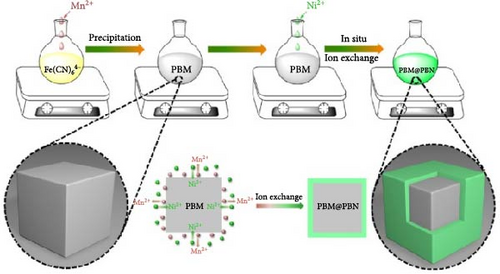
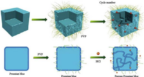
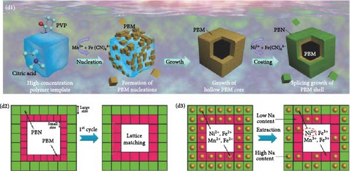


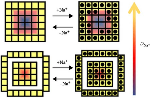
Wan et al. [193] induced a hollow morphology with a stepwise surface during hydrothermal PBA synthesis with benzoic acid. The prepared material showed decreased volume expansion and ion diffusion distance during charge and discharge. Furthermore, they fabricated a composite material from the synthesized material and CNTs to produce a binder-free cathode with high electrical conductivity (Figure 11c). It showed a rate capability of approximately 23% for a 1000-fold increase in discharge rate (100 C vs. 0.1 C).
A core–shell structure with two overlaid shells may effectively increase the kinetics of ion movement within the electrode [38]. Feng et al. prepared a PBM@PBN core–shell structure consisting of MnHCF particles coated with NiHCF to suppress the leaching of Mn2+ during the charge and discharge of MnHCF particles (Figure 11b) [189]. In addition, the external coating layer reduced the volume change of internal particles during cycling. In other words, owing to the NiHCF protective layer, a reversible phase transition in MnHCF was induced during charge and discharge, enhancing the electrode stability. Because of the improved structural stability, this core–shell structure exhibited ~69% rate capability for a 10-fold increase in discharge rate (10 C vs. 1 C).
Huang et al. designed an electrode using PBM@PBN, which consists of a hollow-core–shell structure composed of a MnHCF hollow shell with a NiHCF shell on top (Figure 11d) [190]. This structure prevented the expansion of the hollow-core configuration, thereby enhancing stability by inhibiting the dissolution of Mn3+ due to the Jahn–Teller effect during the charge and discharge of MnHCF. Simultaneously, the shell provided pathways for ion movement. As a result, the material showed a rate capability of ~44% when discharged at a 64 times higher current density (3200 vs. 50 mA g−1).
Here, n, A, and C0 represent the number of electron moles transferred in the redox reaction, the electrode area, and the concentration of active material at the interface, respectively. The ion diffusion coefficient (D) can be obtained from Equation (15). In EIS, ion conductivity can be analyzed from the slope of the low-frequency region in the Nyquist plot, which is related to ion diffusion resistance. Both CV and EIS confirmed that the shortened ion diffusion path in the nanoflower morphology enhances the ion diffusion coefficient compared to the cubic morphology in PBAs. Synthesizing unique PBA structure with a short ion diffusion path is a practical approach to improve the rate capability of electrodes.
Here, τ represents the pulse duration, MB is the mass of the active material, VM is the molar volume of the active material, S is the surface area of the electrode, MB is the molar mass of the active material, ΔEs is the steady-state voltage change after the current pulse, and ΔEt is the voltage change during the current pulse. By substituting ΔEs and ΔEt obtained from the GITT experiments into Equation (16), the ion diffusion coefficient can be calculated. GITT analysis showed that the ultrathin nanosheet-assembled FeHCF exhibited a higher ion diffusion coefficient (D) than the nanoball-structured FeHCF, indicating that the morphology of active particles plays a crucial role in determining ion diffusivity [197].
3.4.3. Etching Surface
Cubic PBA particles can be etched to provide additional pathways for the insertion and extraction of alkali ions while simultaneously reducing the ion diffusion distance within the electrode (Figure 11e,f) [28, 183, 192]. Cubic PBA particles undergo etching starting from the defect-rich regions. They dissolve in a sequence from the corners or edges to the next face, resulting in a morphology resembling concave cubes or nanoframes (Figure 11g) [192]. This increased particle surface area can enhance ion diffusion rates [40, 198].
The pH of the etching solution and etching time must be precisely controlled to achieve selective etching, allowing precise particle morphology control [28]. This means that etching can be broadly categorized into acidic or alkaline etching based on the pH of the etching solution [28]. Notably, etching must be performed within an appropriate pH range because excessively low pH can lead to chemical reactions between H+ and Fe(CN)64− [37]. The reaction between H+ and cyanide creates Fe vacancies within the PBA structure and reduces the number of cyanide groups. The reduced cyanide content within the PBA can be analyzed through the decreased peak around 2500 cm−1 in FT-IR spectra, corresponding to the C≡N triple bond. For instance, Wang et al. confirmed a reduction in the cyanide FT-IR peak in FeHCF synthesized in a highly concentrated HCl solution. This result indicates that FeHCF synthesis in low pH precursor solutions induces significant amount of Fe(CN)6 vacancies [71].
Liu et al. [40] etched the edge portion of PBA in an acidic environment using HCl, obtaining particles with a concave shape. The partial etching and transformation into a concave shape increased the surface area. Despite the external shape changes, crystal structure analysis revealed that the original crystalline structure was well-maintained. As a result, the prepared material exhibited approximately 77% rate capability for a 25-fold increase in discharge rate (5 vs. 0.2 A g−1).
At the same time, Ren et al. [191] induced a unique nanoflower morphology by etching the electrode material using NaOH. In this study, the team used NaOH to disassemble the Fe–C≡N–Ni bonds at the edges of cubic NiHCF, causing their dissolution. During etching, dissolution occurred at the edges of the particles, but the plane surface remained unchanged, allowing ion diffusion through the surface. The shortened ion diffusion distance due to etching enabled efficient ion insertion and extraction (Figure 11h). As a result, the ion diffusion coefficient (DNa+) increased. The material exhibited approximately 46% rate capability for an approximately 40-fold increase in discharge rate (40 C vs. 1.1 C).
4. Summary and Outlook
SIBs highlight their potential to overcome the scarcity and cost of LIBs using abundant sodium. Traditional cathode materials for LIBs struggle with stability and ion transport in SIBs due to larger and heavier sodium ions. PBAs with open cubic frameworks emerge promising for SIBs, facilitating better ion transit and rate capability. The two transition metals composing the PBA determine its electrochemical properties, which in turn affect the choice of electrolytes and the resulting electrochemical performance. Additionally, the open structure of PBA allows for the accommodation of various ions, making it applicable as a cathode material for LIBs, SIBs, and multivalent ion batteries. The versatility of PBAs enables the development of energy devices with tailored properties for diverse applications. This review focuses on the factors affecting the versatility of PBAs with respect to rate capability and discusses synthesis strategies to achieve desired properties. The synthesis conditions play a critical role in determining PBAs’ electrochemical behavior, including the rate capability. Accordingly, the mechanisms of various syntheses are described to understand how the properties were induced. PBAs are synthesized in 0D powder and 2D film forms to suit different electrode needs using methods like coprecipitation, solvothermal, and microemulsion, and electrodeposition. The selected synthesis method affects the PBAs’ physicochemical properties, impacting their rate capability in SIBs.
During the PBA crystallite formation, by combining transition metal cations with hexacyanoferrate anions in an aqueous solution, water is trapped in the crystals in coordinated or interstitial forms. Both forms of H2O defects can hamper charge and discharge kinetics by either being positioned in the pathways of alkali ions inserted into PBA, forming hydrated ions upon interaction with these ions, or distorting and potentially collapsing the framework. When H2O is coordinated with the transition metals in the PBA lattice, it prevents the bonding of Fe(CN)6 anions, forming Fe vacancies. These vacant sites induce structural instability, impeding the insertion/extraction of alkali ions. In addition, Fe is an active charging site; thus, Fe vacancies decrease specific capacity. They also decrease electrical conductivity by disrupting the electron transfer pathways. To enhance the rate capability and stability, it is essential to reduce the quantity of water-related defects and Fe vacancies.
The cubic structure of PBA changes depending on the contents of H2O-related defects, Fe vacancies, and inserted alkali ions. The structure determines the movement of alkali ions and the PBA’s structural stability when used as an electrode material. The defects related to Fe vacancies or water in the lattice are known to partially influence the alteration of the structure. PBA’s phase transition during cycling can induce lattice distortion, potentially impairing mechanical stability. Higher crystallinity mitigates the structural deformation, enhancing the electrode’s mechanical stability. Increasing the crystallinity of PBAs by reducing H2O-related defects and Fe vacancies is essential. The immediate formation of crystal nuclei during PBA synthesis results in the formation of irregular and agglomerated particles, hindering rapid ion insertion/extraction. Therefore, decreases in nucleation and growth rates are expected to result in the formation of uniform and appropriately sized cubic particles, thereby improving rate capability. The size and shape of the particles significantly affect the ion diffusion distance and the specific surface area of the electrode, impacting the alkali-ion kinetics. Essential properties for optimizing PBA’s rate capability include (1) H2O-related defects, (2) Fe vacancies, (3) crystal structure, and (4) morphology, which can be controlled through synthesis conditions (Table 1).
| Shapes of PBAs | Method | Process | Processing condition |
|---|---|---|---|
| 0D | Coprecipitation | Mixing two precursor solutions |
|
| Solvothermal | Heating a precursor solution in an autoclave at high temperature and pressure |
|
|
| Microemulsion | Introducing reactant into a mixture of water and oil |
|
|
|
Electrodeposition | Applying a current or voltage to a substrate in precursor solution |
|
PBAs have shown promising performance as electrode materials for high-rate SIBs because of their open-framework structure. However, the instantaneous nature of PBA synthesis leads to the formation of H2O-related defects and Fe vacancies within the lattice, which reduce the crystallinity, nonelectric capacity, and rate capability of the prepared materials. Therefore, elucidation of the reaction mechanisms of various synthesis processes is essential for comprehending the formation of these defects. Based on the principles of synthesis processes, we discussed process conditions that can be used to control these defects. In addition to defects, morphology and crystal structure considerably affect the electrochemical properties of PBAs. Many researchers have strived to control these characteristic factors to achieve high-rate capability. To this end, researchers have investigated the effects of various synthesis methods and factors on the physicochemical properties and rate capability of PBAs. Table 2 summarizes their findings, highlighting the key parameters that influence these characteristics. The growing demand for high-output energy sources necessitates the understanding and control of the kinetics of alkali-ion insertion and extraction in PBAs to make PBAs practical electrode materials for various high-power devices.
| Controlled factor | Approach | Condition | Sample (composition) |
Controlled property | Synthesis method | Specific capacity (mAh g−1) |
Rate capability (%) | Stability (%) | Working Potential (V) |
Ref |
|---|---|---|---|---|---|---|---|---|---|---|
| H2O-related defects | Selection or concentration of intercalated guest ion |
|
|
Reduced water contents | Coprecipitation |
|
|
|
|
[123] |
|
|
Coprecipitation |
|
|
|
|
[144] | |||
| Na-rich FeHCF synthesis |
|
Coprecipitation |
|
|
|
|
[199] | |||
| Use of additives in precursor solution | Sodium citrate additive |
|
Coprecipitation |
|
|
|
|
[145] | ||
|
|
Coprecipitation |
|
|
|
|
[200] | |||
| PVP additive |
|
Hydrothermal |
|
|
|
|
[146] | |||
| Adjusting pH and concentration of precursor solution |
|
|
Coprecipitation |
|
|
|
|
[138] | ||
| Precursor solution prepared with ethanol (solvent) |
|
Coprecipitation |
|
|
|
|
[143] | |||
| Postsynthesis treatment | Postannealing |
|
Coprecipitation |
|
|
|
|
[48] | ||
| Fe vacancies | Introducing dopants | Ni doping in Fe site |
|
Reduced Fe vacancies | Hydrothermal |
|
|
|
|
[151] |
|
Coprecipitation |
|
|
|
|
[201] | ||||
| Use of additives in precursor solution |
|
|
Coprecipitation |
|
|
|
|
[131] | ||
|
|
Coprecipitation |
|
|
|
|
[130] | |||
|
|
Coprecipitation |
|
|
|
|
[202] | |||
| Adjustment of the coprecipitation reaction conditions |
|
|
Solvothermal |
|
|
|
|
[82] | ||
|
|
Coprecipitation |
|
|
|
|
[150] | |||
|
|
Coprecipitation |
|
|
|
|
[156] | |||
|
|
Hydrothermal |
|
|
|
|
[157] | |||
| Crystal structure | Addition of dopant | Ni doping in Co site |
|
Induced monoclinic (P21/n) phase | Coprecipitation |
|
|
|
|
[169] |
| Zn doping in Co site |
|
Induce rhombohedral () phase | Coprecipitation |
|
|
|
|
[171] | ||
| Fe doping in Mn site |
|
Reduced structural distortion during cycle | Coprecipitation |
|
|
|
|
[173] | ||
| Co coping in Mn site |
|
Induce rhombohedral () phase | Coprecipitation |
|
|
|
|
[172] | ||
| Addition of additives in precursor solution | Sodium citrate (chelating agent) |
|
Reduced structural distortion during cycle and discharge | Coprecipitation |
|
|
|
|
[168] | |
| Sodium carboxymethyl cellulose (CMC) (chelating agent) |
|
Coprecipitation |
|
|
|
|
[39] | |||
| Control of synthesis condition |
|
|
Induced rhombohedral phase | Coprecipitation |
|
|
|
|
[170] | |
| Morphology | Reducing particle size |
|
|
|
Coprecipitation |
|
|
|
|
[187] |
|
|
Coprecipitation |
|
|
|
|
[45] | |||
| Short mixing time and use of chelating agent |
|
|
Coprecipitation |
|
|
|
|
[46] | ||
| Formation of unique particle shapes | Etched by benzoic acid precursor solution (solvent) |
|
Stepwise shaped cube particle | Hydrothermal |
|
|
|
|
[193] | |
| Coated with other PBA |
|
|
Coprecipitation |
|
|
|
|
[189] | ||
|
|
Coprecipitation |
|
|
|
|
[190] | |||
| Etching surface |
|
|
|
Hydrothermal |
|
|
|
|
[40] | |
|
|
|
Coprecipitation |
|
|
|
|
[191] | ||
- Note: Some values were reprocessed to present consistent significant figures for uniformity from the values reported in references. Some values were calculated based on figures presented in the paper in instances where numerical values were not explicitly provided.
Disclosure
The article is based on a review of existing literature.
Conflicts of Interest
The authors declare no conflicts of interest.
Author Contributions
San Chun Kang and Na Yeong Song contributed equally to this work.
Funding
This work was supported by the National Research Foundation of Korea (NRF) grant funded by the Korean government (Ministry of Science, ICT & Future Planning) (NRF-2022R1A2C1009922).
Acknowledgments
This work was supported by the National Research Foundation of Korea (NRF) grant funded by the Korean government (Ministry of Science, ICT & Future Planning) (NRF-2022R1A2C1009922).
Open Research
Data Availability Statement
No original data were generated, and all data sources are derived from previously published literature, which has been cited within the article.


