Enhancing Hydrogen Storage Performance of Metal Hydrides in Ships: A Review
Abstract
Some metals and metal alloys can store gaseous hydrogen (GH2), making the storage of hydrogen in metal hydrides (MHs) possible. The present work aims to explore the development of marine MHs and technologies for enhancing hydrogen storage performance while identifying future research priorities. First, the mechanism of MHs hydrogen storage is summarized and its applications in the maritime field are introduced. Subsequently, the technical and economic feasibility of utilizing MHs hydrogen storage technology in ships is analyzed along with the application scenarios and requirements of ship-based MHs. Furthermore, to meet the target requirements for hydrogen storage properties in ship power systems, this review focuses on several aspects: the hydrogen storage materials, reactor structural parameters, hydrogen storage operating conditions, and thermal management optimization. The factors influencing the performance of MHs hydrogen storage systems and their impacts are summarized. Strategies to enhance the performance of MHs hydrogen storage are proposed and technologies for heat transfer enhancement in MHs hydrogen storage, along with the corresponding thermal management systems, are introduced. Finally, future research directions for ship-based MHs hydrogen storage are outlined: developing new synthesis routes for novel MH hydrogen storage materials; creating microchannel hydrogen storage reactors with excellent hydrogen storage and heat transfer performance and conducting combined optimization analyses of multiple reactor structural parameters and operational parameters; coupling phase change materials (PCMs) to enhance the energy utilization efficiency of the hydrogen absorption and desorption process; reasonably regulating the kinetics of the hydrogen storage system to ensure the dynamic stability coupled with hydrogen fuel cells; and constructing intelligent hydrogen storage systems based on deep learning methods to improve the predictive and decision-making capabilities for hydrogen storage performance and thermal management. Through exploring these research directions, MHs hydrogen storage technology is anticipated to achieve greater efficiency and wider applications in the future.
1. Introduction
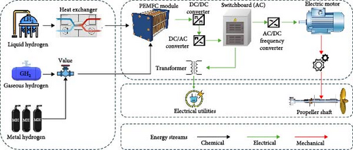
The shipping industry is facing the growing challenge of increasing greenhouse gas emissions [1]. The International Maritime Organization (IMO) has established a long-term goal to reduce greenhouse gas emissions by 50% by 2050 compared to 2008 levels [2–4]. In light of the increasingly stringent domestic and international carbon emission regulations, green shipping has evidently become a focal point of global research. To achieve emission reduction targets, the shipping industry typically employs the following strategies: installing renewable energy systems on vessels [5]; using low-emission energy sources to replace traditional fuels [6–8]; and optimizing ship design to reduce resistance and energy consumption [9]. Among the potential alternative fuels, hydrogen energy has emerged as one of the most promising energy carriers due to its high energy density (high calorific value of ~142 MJ/kg), abundant availability, and clean and carbon-free characteristics. It is widely applied in transportation, industry, power generation, and other fields [10, 11]. Specifically, hydrogen-powered vessels are gaining significant attention as low-carbon and environmentally friendly transportation options in the energy transition of the shipping industry [12]. The energy flow diagram of a hydrogen powered ship is shown in Figure 1.
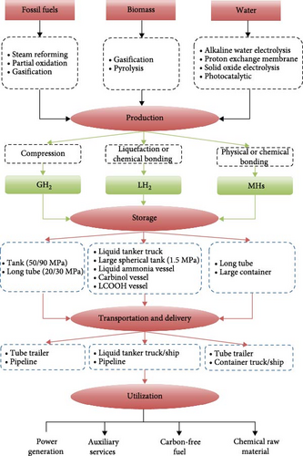
Despite the above advantages, the adoption of hydrogen as a primary energy carrier still faces considerable obstacles, mainly related to hydrogen storage and transportation [11, 14]. As shown in Figure 2, the entire hydrogen energy industrial chain consists of three key links: hydrogen production, hydrogen storage, and hydrogen utilization. Advances in hydrogen production technology can reduce the cost of hydrogen production, while storage and transportation technologies are the bottlenecks for the large-scale commercial application of hydrogen energy [15–18]. Currently, there are three main methods for hydrogen storage: gaseous hydrogen (GH2) storage, liquid hydrogen (LH2) storage, and solid-state hydrogen storage [19–22]. The physical and chemical properties, production characteristics, and safety features are the three main indicators for evaluating hydrogen storage technologies [23], as shown in Table 1.
| Performance | 70 MPa Type IV thanks [21–28] | Liquid hydrogen [26–30] | Liquid ammonia [43] | Methanol [37–41] | Methylcyclohexane [32] | Dibenzyl-toluene [33] | Ethyl-carbazole [34] | MgH2 [44–52] |
|---|---|---|---|---|---|---|---|---|
| Mass density (%wt) | 5.9 | – | 17.8 | 12.5 | 6.2 | 6.23 | 5.8 | 7.6 |
| Volume density (kg/H2/L) | 0.059 | 0.071 | 0.109 | 0.099 | 0.047 | 0.048 | 0.056 | 0.11 |
| Calorific value (Ml/l) | 244 | 294 | 451 | 410 | 195 | 199 | 235.7 | – |
| Energy density (kWh/L) | 2.3 | 2.8 | 4.3 | 3.3 | 1.85 | 1.9 | 2.25 | – |
| Synthesis conditions | – | – |
|
|
|
|
|
|
| Dehydrogenation conditions | – | – |
|
|
|
|
|
200–300°C |
| Hydrogen storage energy consumption |
|
|
|
|
15.41 | 12.57 | 12 | 12 |
| Explosive limit | 4%–75.6% | 4%–75.6% | 16%–25% |
|
6.7% | Nonexplosive | Nonexplosive | 4%–75.6% |
| Toxicity | No | No |
|
Yes | Slightly | No | Yes | No |
| Corrosivity | No | No |
|
No | Yes | No | No | No |
| Circulating medium | – | – | Ammonia | Carbon | Organic carrier | Organic carrier | Organic carrier | Mg |
High-pressure GH2 storage technology occupies an important position in the current hydrogen energy industry due to its relative maturity and lower costs, leading to widespread application [21, 24, 25]. However, there are some significant issues concerning its physical and chemical properties. First, the low mass density of hydrogen poses a major challenge. For example, the mass density of GH2 at 70 MPa is only 1/6 that of gasoline at the same volume, meaning that the energy stored in hydrogen gas is far lower than that of gasoline when considering the same volume [26]. These characteristics limit the competitiveness of high-pressure GH2 storage technology in terms of energy density. Second, using low alloy steel for hydrogen storage and transportation can lead to hydrogen embrittlement. Because the Bohr radius of hydrogen atoms is small (only 0.053 nm), they can easily diffuse into the gaps of the metal lattice, leading to crack initiation and affecting the pressure resistance of the tank [27]. So, high-pressure GH2 storage technology is advancing towards higher pressures (such as 70 MPa) and improved tank types (such as Type IV). Type IV hydrogen storage tanks utilize a dense resin structure for the inner layer, combined with high-toughness carbon fiber and high-strength glass fiber, significantly reducing the risk of hydrogen embrittlement. These improvements have resulted in a 27% reduction in the cost of hydrogen cylinders under the same pressure conditions, while the mass density has increased to 5.9%wt, further enhancing their market competitiveness [28]. Despite the advantages of high pressure GH2 storage technology in terms of simple operation, continuous improvements in its physical and chemical properties are still needed to meet the growing demand for hydrogen energy and safety standards.
Compared to GH2, LH2 offers higher storage density and capacity [26]. Estimates indicate that the volumetric density of LH2 is 1.2–1.5 times that of GH2 at 70 MPa [29]. However, the production process involves significant energy consumption and technical challenges. First, the storage process of LH2 involves gas compression, heat release, heat transfer for cooling, heat absorption during expansion (Joule–Thomson effect), liquefaction, and storage. The total energy consumption represents approximately one-third of the energy contained in the LH2 itself [30]. Second, LH2 storage tanks must be constructed using ultralow temperature materials, and there are strict requirements for insulation and prevention of evaporation during storage and transportation [31]. Organic hydrogen storage, which falls under the category of LH2 storage, involves reacting hydrogen with unsaturated organic compounds to store hydrogen in organic liquids such as methylcyclohexane, dibenzyl toluene, and ethyl carbazole [32–34]. To ensure the stability of hydrogen storage performance, hydrogenated compounds typically require inert carriers. The dehydrogenation process must occur at high temperatures (150–400°C) and under precious metal catalytic conditions, making it a high-energy process. Additionally, organic LH2 storage involves a multiphase mixed reaction process that requires complex reactor structures, which somewhat limits the applicability of this technology [35, 36]. Existing vessels can also be equipped with carbon capture, utilization, and storage (CCUS) systems to capture the carbon dioxide emitted from diesel combustion. This captured carbon dioxide can be mixed with hydrogen and after being pressurized and heated, it can be synthesized into methanol using a catalyst in a synthesis tower for use as an alternative fuel. From a production perspective, methanol requires the lowest hydrogen storage energy consumption, approximately 1/8–1/11 of that required for other fuels [37–41]. However, strictly speaking, this solution is not carbon-free and therefore does not meet the long-term carbon reduction targets set by the IMO [42]. Additionally, nitrogen can be separated from air and mixed with it to synthesize liquid ammonia as an alternative fuel using the Haber process. Liquid ammonia has excellent physical and chemical properties, with a mass density of 17.8%wt, a volumetric density of 0.109 kg H2/L, a calorific value of 451 mol/L, and an energy density of 4.3 kWh/L [43]. Furthermore, ammonia consists only of nitrogen and hydrogen, making it a carbon-free energy storage option. Despite the advantages of hydrogen storage technology in terms of storage density and capacity, there are still challenges related to production characteristics, particularly regarding energy consumption and technical complexity. Further optimization of the production and storage processes is needed.
Metal hydrides (MHs) hydrogen storage refers to the reversible chemical reaction between certain metals or alloys and hydrogen gas, allowing hydrogen to be stored in the crystal lattice as MHs [45]. This method has favorable physical and chemical properties as well as safety features [44–46]. Taking magnesium-based hydrogen storage as an example, it has the highest volumetric density among various hydrogen storage methods, approximately 0.11 kg H2/L [47–49]. Magnesium-based solid-state hydrogen storage is also nontoxic, noncorrosive, and the cycling medium magnesium can be reused multiple times. The hydrogen storage conditions for ferrotitanium and rare earth alloys are less severe than those for GH2 and LH2 [50–53]. However, the thermal effects during hydrogen absorption and desorption reactions can inhibit the progress of the reactions, often necessitating a more complex reaction structure or external means to address the issue of heat transfer during the reactions.
To address the research challenges, the study of MHs hydrogen storage technology mainly focuses on the following aspects: Preparation of high-performance MHs hydrogen storage materials: Synthesizing novel composite materials with higher gravimetric density, superior reaction kinetics, and better cycling stability. Optimization of MHs hydrogen storage reactor structural parameters and operating conditions: Improving the heat exchange in the reaction process by optimizing structural and operational parameters to achieve maximum reaction rates and hydrogen storage capacity. Optimization of thermal management systems: Enhancing energy utilization efficiency while increasing the dynamic stability of the system.
2. Mechanism of Hydrogen Absorption and Release of MHs
2.1. MHs Hydrogen Storage Technology
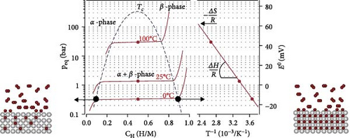
The hydrogen absorption and desorption reaction of MHs is a reversible process accompanied by strong thermal effects and mass transfer, involving the adsorption, dissolution, and release of hydrogen, as shown in Equation (1) [54]. The thermodynamic characteristics of this reaction process can be tested and studied using pressure–composition–temperature (P–C–T) diagrams, which include three stages, as illustrated in Figure 3: As the concentration of hydrogen gas increases, the system pressure gradually rises. At this stage, hydrogen does not react with the material, and the hydrogen storage alloys remain in the solid solution (α-phase). When the system reaches the equilibrium pressure (Peq) at that temperature, hydrogen molecules adsorb onto the metal surface and dissociate into atoms, which then diffuse into the metal lattice to form a solid solution. The hydrogen concentration increases while the system pressure remains constant. This indicates that the increased hydrogen concentration is not entirely absorbed by the material. The hydrogen storage alloys are transformed into MHs (β-phase). Further increases in hydrogen concentration result in the material being unable to absorb hydrogen normally, leading to a continuous increase in system pressure. In the coexistence of α- and β-phases, the P–C–T curve exhibits an equilibrium state [55].
In addition, MHs hydrogen storage is a complex multiphysical field coupling process that includes mass transfer of hydrogen within the reactor, heat transfer between the heat transfer fluid and the bed, momentum transfer during fluid flow, and the chemical reaction processes between the hydrogen storage material and hydrogen gas. The mass transfer process involves the introduction of mass balance equations, while the fluid heat transfer process requires the inclusion of energy equations. The specific processes are as follows:
2.2. Application of MHs in the Maritime Sector
In marine applications, hydrogen storage devices can be used as ballast weight for vessels to mitigate the effects of the low mass density of MHs and reduce the impact of ballast water sloshing on the stability of the ship [57]. At the same time, autonomous underwater vehicles (AUVs) require larger ballast weights to submerge and compensate for the buoyancy of low-density payload spaces [58]. Additionally, due to factors such as vibrations, shocks, high humidity, and salt spray corrosion that ships encounter during navigation, as well as the flammable and explosive nature of hydrogen, which is prone to leakage due to its low density, the safety of hydrogen storage is crucial for the widespread application of hydrogen-powered vessels. Compared with traditional hydrogen storage methods, MHs have the characteristic of lower storage pressure, which reduces the risk of leakage [59]. Additionally, MHs avoid the issue of hydrogen embrittlement in containers, thus, enhancing safety [60].
MHs were first applied in the military sector. In 1990, the German company HWD modified the hydrogen-powered submarine “U212,” which features a propulsion system composed of a traditional power system and an air-independent propulsion (AIP) system. AIP system comprises nine sets of PEM fuel cells, two liquid oxygen storage tanks, and titanium-iron alloy hydrogen storage containers, with each set having a power output between 30–50 kW for slow cruising. Using the PEMFC alone, the cruising speed can reach 8 knots [61].
Over time, technology gradually developed and was applied to civilian vessels and AUVs. In 2003, the German company MTU developed the “Sailing Boat,” which uses a MHs hydrogen storage container coupled with a PEMFC unit to provide power for the vessel. The ship has a rated power of 4.8 kW and can travel 225 km at a speed of 6 km·h−1 [62]. In 2005, the Japan Agency for Marine-Earth Science and Technology developed the “URASHIMA” AUV, which also uses an MHs hydrogen tank coupled with a PEMFC unit for power. This AUV can achieve an average cruising speed of 2.8 knots at a depth of 800 m, with a cruising time of 54 h [63]. In 2007, the University of Birmingham in the UK and the EMPA laboratory in Zurich jointly developed the “Ross Barlow,” a hydrogen-powered canal boat. Its propulsion system consists of a Ti0.93Zr0.05(Mn0.73V0.22Fe0.04)2 hydrogen storage container, a 1 kW PEM fuel cell, lead–acid batteries, and a permanent magnet motor. The MHs hydrogen storage capacity of this vessel is 4 kg and after 1000 hydrogen absorption/desorption tests, the capacity loss was only 5% [64]. The innovative zero-emission vessel “ZEUS,” funded by Fincantieri–Isotta Fraschini S.p.A and the Italian Ministry of Economic Development (MISE), has a power system consisting of a 144 kW PEM fuel cell and two lithium battery packs (storing 150 kWh of energy), with a MH hydrogen storage system that can store 50 kg of hydrogen [65]. In 2024, the Dutch shipyard Next Generation will launch the world’s first salt-storage solid-state hydrogen-powered ship, “Neo Orbis,” which will enter operation. This vessel utilizes sodium borohydride (NaBH4), a salt that releases hydrogen when in contact with water and a catalyst, to power its fuel cells. At a speed of 12 km·h−1, it can sustain operation for up to 7 h [66].
3. Feasibility Analysis of MHs for Marine Applications
3.1. Technical Feasibility
First, due to the lower gravimetric energy density of MHs, which means for storing the same amount of energy, the weight of MHs is greater. This is one of the reasons why the hydrogen storage method using MHs has not been widely applied in mobile applications [8, 66, 67]. However, in the maritime sector, this drawback can be mitigated because MHs reactors can serve as ballast for the vessel, thereby countering the impact of the low gravimetric energy density of MHs [57]. This is particularly relevant for AUVs, which require a greater ballast weight for submersible operations, while also compensating for the buoyancy caused by low-density payload space [58].
Second, as maritime transport vehicles, ships have strict spatial requirements, especially when the fuel tank space is limited, necessitating special attention to the volume of fuel and storage devices [68, 69]. Compared to conventional fuels, larger fuel storage spaces are required [70]. Micco et al. [71] analyzed the feasibility of replacing a diesel engine with an 8.3 MW PEMFC system based on a chemical tanker and compared the volume and mass of the engine room and fuel tanks for both scenarios. The results showed that, compared to the diesel engine system, the new power system reduced the occupied engine room space by approximately 3.5% and mass by about 40.5%, creating additional space in the engine room for fuel storage. Estimates of the additional mass brought by compensating hydrogen storage technologies indicated a reduction in the ship’s cargo capacity: a decrease ranging from 1.3% to 1.1% for GH2, 0.1% for LH2, and 9% for MHs. To promote the commercial viability of shipboard MHs hydrogen storage systems, researchers should explore multiple approaches to increase the volumetric energy density of MHs, which is crucial for enhancing the hydrogen storage capacity of shipboard MHs. Furthermore, designers have placed the MHs hydrogen storage devices in the keel area. This not only addresses the issue of the large space occupied by MHs hydrogen storage devices but also enhances stability during navigation [72].
Another complex issue is the thermal management system, ideally one that utilizes the waste heat or byproduct heat from the ship’s systems to efficiently desorb hydrogen from the MHs [73]. This will be discussed in more detail later. Cavo et al. [65] established a thermal coupling model between the MHs hydrogen storage tank and the PEMFC based on offshore operating conditions. The research found that the thermal power required for hydrogen desorption necessary for the normal operation of the PEMFC is approximately 25% of the heat generated by the PEMFC. On the one hand, this makes waste heat utilization possible, improving energy efficiency; on the other hand, it reduces the investment costs associated with separate thermal management systems.
3.2. Economic Feasibility
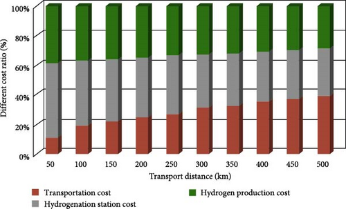
From the perspective of the three major indicators, there is no perfect hydrogen storage solution; comprehensive costs and application scenarios must be considered. As shown in Figure 4, the current high cost of hydrogen is largely due to excessive transportation costs, which account for approximately 30%–40% of the total cost [74]. Therefore, reducing costs has become the key to overcoming the “bottleneck” issues in hydrogen storage [15, 75].
3.2.1. Economic Analysis of Hydrogen Refueling
In a recent study, Zhang et al. [74] evaluated the overall economic costs of the hydrogen supply chain, from hydrogen production plants to terminal refueling stations. They included equipment investment costs, operating costs, labor costs, and maintenance costs associated with the hydrogen storage and transportation process, considering the impact of transportation distance. The assessment results are shown in Table 2: when the transportation distance exceeds 200 km, the storage and transportation costs of hydrogen account for more than 20% and increase with the transportation distance. Since there is no need to invest in raw gas compression and liquefaction equipment, MHs hydrogen storage demonstrates a clear advantage in operating costs over gaseous and liquid storage methods for distances within 500 km. However, in the field of mobile applications, the economic cost analysis should focus primarily on two aspects: the cost of hydrogen refueling and the storage costs during the transportation process [57, 76].
| Hydrogen storage mode | 100 km | 300 km | 500 km |
|---|---|---|---|
| GH2 | 7 RMB | 21 RMB | 35 RMB |
| LH2 | 18 RMB | 20 RMB | 22 RMB |
| MHs | 4 RMB | 12 RMB | 20 RMB |
The refueling of GH2 can cause a rapid increase in both temperature and pressure inside the hydrogen storage tank. On the one hand, this can result in the pressure of the refueling machine equalizing with the pressure inside the storage tank, leading to an interruption of the refueling process. On the other hand, it can damage the walls of the storage tank, ultimately posing safety risks. Typically, additional compressors or cascading equipment are required to address these issues, as hydrogen is reintegrated into the high-pressure buffer tank of the cascading system via the compressor [77]. The refueling of LH2 has stringent requirements for temperature and pressure. It usually requires a low-temperature and high-pressure pump to transport the LH2 to an evaporator. The high-pressure hydrogen gas produced from vaporization also needs to be directed into a high-pressure buffer tank, where it is precooled to −40°C using a cooling device before being used to refuel mobile equipment [14]. The introduction of high-pressure buffering equipment means that these two types of refueling stations must be equipped with systems that have higher pressure control precision and faster response times. Additionally, the precooling treatment before refueling is crucial for the safe operation of the refueling station. All these factors somewhat increase the refueling costs. The hydrogen refueling scheme for MHs is relatively simpler. During hydrogen refueling, it only requires increasing the pressure to be increased via a compressor to match the equilibrium pressure for hydrogen absorption by the MHs. When using a high-pressure hydrogen source for refueling, the pressure must be reduced to connect to a buffer tank that is close to the hydrogen absorption pressure of the MHs for the refueling process [78]. Therefore, compared to the refueling processes of GH2 and LH2, the hydrogen refueling process for MHs operates at lower pressures and has simpler control systems, significantly reducing the investment costs of refueling stations.
Danebergs and Deledda [57] calculated the costs associated with different hydrogen production and onboard storage schemes, considering the costs of hydrogen production, compression, transportation, land storage, distribution, and tank costs. Two hydrogen production methods were evaluated: distributed local production of compressed hydrogen (Scheme A) and centralized production of compressed hydrogen (Scheme B). The onboard hydrogen storage solutions included GH2 storage, LH2 storage, and MHs storage. The study discussed two different supply scenarios representing low daily demand (100 kg/day) and high daily demand (1500 kg/day). Economies of scale resulted in varying costs among the different schemes. Specifically, the MHs storage option, due to its simpler refueling process, exhibited lower costs for the centralized hydrogen refueling scheme under low demand conditions. Conversely, in the case of high demand, the increased refueling volume helped distribute the costs of production and compression facilities more effectively, while the proportion of transportation costs significantly decreased. This made the local hydrogen production and refueling scheme more economically advantageous in high-demand scenarios.
Thus, based on the cost analysis of the hydrogen energy full industry chain and the hydrogen refueling segment for mobile devices, MHs hydrogen storage technology has certain advantages, particularly for refueling scenarios with relatively low demand and transportation scenarios over shorter distances.
3.2.2. Cost Analysis of Hydrogen Storage System
The cost of hydrogen storage depends on the costs of hydrogen storage materials and hydrogen storage reactors. The preparation of materials requires alloying metals, nanostructuring, catalysis, or further processing to enhance the hydrogen storage performance of the materials [79]. Similarly, the structural design of the reactor is crucial. The complex heat exchange structure can enhance the heat transfer efficiency. Particularly in confined spaces like ship compartments, a separate thermal management system may also need to be implemented. All these factors significantly constrain the costs of MHs hydrogen storage systems.
Amica, Larochhette, and Gennaria [78] developed competitive Mg(NH2)2–2LiH composite hydrogen storage materials based on the locally abundant reserves of Mg and Li metals. They established a hydrogen storage module with a capacity of 4 kg, with a unit cost of $28,000–$35,000. It is estimated that when production reaches 10,000 units, the unit cost will decrease to $5300–$6700. Additionally, they compared the costs of MHs hydrogen storage systems and high-pressure hydrogen storage systems. The cost ratio between these two options is at least 2:1 or even higher. Furthermore, the U.S. Pacific Northwest National Laboratory [80] established a dual-reactor module based on NaAlH4 hydrogen storage material, with a storage capacity of 5.6 kg. They estimated that when production reaches 10,000 units, the cost of the hydrogen storage system would be approximately $20,200, with material and reactor costs each accounting for 50%. If production is further scaled up to 500,000 units, the cost of the hydrogen storage system would drop to $8,000. In the maritime sector, although most hydrogen-powered vessels launched domestically and internationally currently use high-pressure gas cylinders as the hydrogen energy source for propulsion, neither gaseous nor LH2 storage fundamentally resolves the safety issues associated with large-scale hydrogen storage. Moreover, when comparing technologies of varying maturity, there remains potential for optimization in the use of MHs for hydrogen storage, which is an area of ongoing research and effort among scientists.
4. Research on MHs Hydrogen Storage Systems in Ship
In the field of ship applications, the MHs hydrogen storage system is required to fulfill the hydrogen reserve demands of the power system during the ship’s navigation and the hydrogen release rate requirements of the PEMFC for the MHs reactor. The most straightforward method is to meet the hydrogen reserve requirements by increasing the hydrogen storage material capacity in a single reactor or the number of reactors. Nevertheless, this would raise the thermal management cost and equipment cost. This involves several distinct factors: First, the hydrogen storage material must possess the optimal mass hydrogen storage density, hydrogen absorption and desorption kinetics performance, and cycle stability. Second, the hydrogen storage performance of the MHs reactor must be guaranteed within the specific application space and weight constraints. Third, the MHs reactor must complete the hydrogen absorption and desorption process with the highest efficiency within the prescribed time. Therefore, the MHs hydrogen storage materials, the structure of the MHs reactor, operating conditions, and thermal management are of crucial significance for the research of the MHs hydrogen storage system [81]. The following will carry out an in-depth discussion from these aspects.
4.1. MHs Hydrogen Storage Material
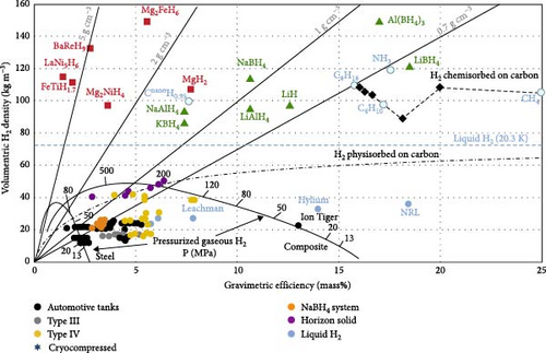
In the context of hydrogen energy’s potential as a clean energy source being widely acknowledged, research into MHs hydrogen storage materials has garnered increasing attention [44, 82]. Materials suitable for MHs hydrogen storage must fulfill specific criteria, primarily encompassing mass hydrogen storage density, thermodynamic properties, and kinetic characteristics [83]. Figure 5 illustrates the volume and mass hydrogen storage densities of various hydrogen storage methods. Presently, studies on marine MHs hydrogen storage materials predominantly concentrate on intermetallic compounds, including AB2, AB5, MgH2, and AB types [85]. The corresponding mass hydrogen storage densities are detailed in Table 3. Due to inherent material characteristics, the mass hydrogen storage density of MHs is relatively low. However, for ships, endurance is a critical factor in evaluating performance, and the mass hydrogen storage density of MHs significantly influences this endurance. Consequently, synthesizing MHs with enhanced mass hydrogen storage density remains a pivotal research direction.
| Alloy typic | Typical representative | Mass hydrogen storage density (%) | Operating temperature (°C) | Working pressure (MPa) |
|---|---|---|---|---|
| AB2 | TiMn2 | 2.00 | −21 | 0.84 |
| AB5 | LaNi5 | 1.49 | 12 | 0.18 |
| Mg-based | MgH2 | 7.6 | 320 | — |
| AB | TiFe | 1.86 | −8 | 0.41 |
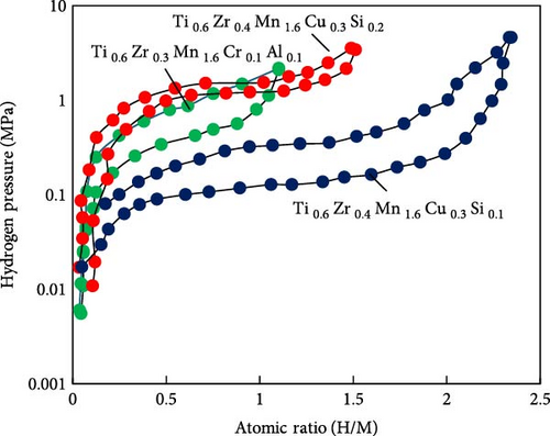
The A-side of AB2-type hydrogen storage alloys is predominantly composed of Ti and Zr elements, while the B-side typically includes V, Ni, Mn, Cr, Cu, and other elements. Common series include Ti–Mn, Ti–Cr, Zr–V, and Zr–Mn. Due to its advantages such as ease of activation, rapid reaction kinetics, robust cycle stability, and low cost, TiMn2 has become the most widely used material in this category [86]. For instance, Bevan et al. [84] developed a hydrogen-powered river boat that utilized a power system combining PEMFC with an MHs reactor. The hydrogen storage material for the MHs reactor was TiMn2 alloy, achieving a mass hydrogen storage capacity of up to 2.0%. However, this alloy exhibits high hydrogen absorption pressure (0.8–1.2 MPa) and significant reaction lag. To address these issues, Fiori et al. [87] reviewed a range of MHs materials suitable for submarines. They proposed that incorporating elements such as Zr, Cr, V, Ni, Cu, Al, and Si into Ti–Mn alloys could form more complex atomic structures, thereby, significantly enhancing the performance of TiMn2. This approach aims to increase the ship’s hydrogen storage capacity and improve its autonomy (independent air propulsion). Additionally, optimizing the elemental ratios can yield MHs hydrogen storage materials with superior performance. For example, adding Si can enhance hydrogen storage capacity to some extent, but excessive Si content negatively impacts both hydrogen storage capacity and equilibrium pressure, as illustrated in Figure 6. Currently, typical marine applications of TiMn–based AB2-type hydrogen storage alloys include hydralloy C5 (Ti0.95Zr0.05Mn1.46 V0.45Fe0.09) [88] and HWT5800 (Ti0.98Zr0.02V0.43Fe0.09Cr0.05Mn1.5) [89].
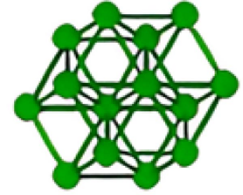
As a quintessential representative of traditional MHs hydrogen storage materials and AB5 alloys, LaNi5 exhibits several advantages including facile activation (operable at room temperature and a pressure of 1.8 bar), rapid reaction kinetics, and resistance to impurities. Consequently, it is extensively utilized in scenarios where the temperature differential remains below 100°C, such as in submarines [90, 91]. The hydrogen storage performance of this material can be further enhanced through elemental substitution. For instance, substituting Ni with small quantities of Al, Co, and Mn (other potential elements include Cu, Cr, Sn, Fe, Ga, Ge, Zn, Pt, etc.) can improve various properties. Replacing Ni with Al enhances cyclic stability while reducing the reaction equilibrium pressure. Partial substitution of Al with Mn decreases the reaction equilibrium pressure without compromising hydrogen storage capacity. Incorporating Co in place of some Al improves electrochemical oxidation resistance. Substituting part of La with Ce, Pr, and Nd (or using rare earth element mixed metals like Mm) increases the reaction equilibrium pressure [92]. For example, Minato et al. [93] experimentally compared the hydrogen storage characteristics of MmNi4.16Mn0.24Co0.5Al0.1 alloy and LaNi5 alloy. Their findings indicated that by controlling hydrogen pressure, the hydrogen storage capacity of MmNi4.16Mn0.24Co0.5Al0.1 alloy is approximately double that of LaNi5 alloy. Moreover, after 1000 cycles, the hydrogen storage capacity of the alloy remains 7% higher than its initial value. Additionally, considering the high cost of rare earth elements like La, they can be substituted with Ti, Zr, or Mg. Presently, commonly employed AB5-type hydrogen storage alloys include La0.5Nd0.5Al0.1Fe0.4Co0.2Ni4.3 and LaNi4.8Al0.2, among others.
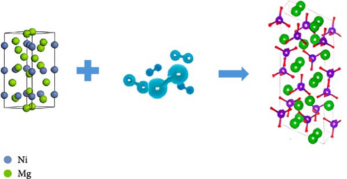
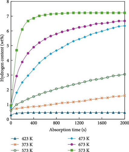
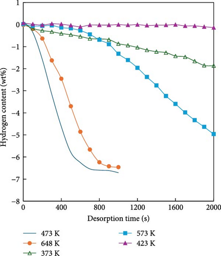
MgH2 exhibits a high mass hydrogen storage density and magnesium is cost-effective and readily available. However, several challenges hinder its application in mobile systems such as ships. First, the hydrogen diffusion rate within MgH2 is relatively slow, resulting in low rates of hydrogen absorption and desorption. Second, the strong chemical bond between Mg and H requires significant energy for hydrogen desorption, approximately 75 kJ/mol H2 [94], leading to a high reaction temperature of around 300°C. This high temperature not only complicates transportation but also induces sintering of Mg, thereby, degrading the material’s cycling stability. To address these issues, the hydrogen storage performance of MgH2 can be enhanced through alloy doping, nanoscaling, nanoconfinement, and the addition of catalysts [95]. Specifically, to address the thermodynamic instability and challenging decomposition of MgH2, Reilly and Wiswall [94] introduced elemental Ni into MgH2 to synthesize Mg2NiH4. As illustrated in Figure 7, the enthalpy changes of Mg2NiH4 decreased from 75 to 64.5 kJ/mol. This reduction is attributed to the weaker bond energy between Ni and H compared to that between Mg and H, thereby lowering the dissociation energy during dehydrogenation. Similarly, alloying studies have incorporated various monometallic elements such as Ti, Fe, Co, Pd, Ag, binary alloys (e.g., ZrMn2, TiMn2) and multicomponent alloys (e.g., Ti0.4Cr0.15Mn0.15V0.3). Table 4 summarizes the hydrogen storage capacities and enthalpy values of different Mg-based hydrogen storage alloys [94–101]. Through these alloy doping methods, the dehydrogenation temperature can be reduced by approximately 100 K. Another approach involves processing materials into nanoscale powders, including three-dimensional nanoparticles (NPs), two-dimensional nanofilms, one-dimensional nanowires, and zero-dimensional nanoclusters, using techniques such as ball milling, electron beam evaporation, ultrahigh vacuum sputtering, vapor deposition, and chemical reduction [44, 102–107]. These processes enhance the material’s relative surface area, surface energy, and grain boundary density [108–111]. Huot et al. [112] compared the hydrogen absorption and dehydrogenation properties of MgH2 with and without ball milling, as shown in Figure 8. The hydrogen desorption temperature of MgH2 was reduced by 64 K and the hydrogen desorption rate was enhanced fivefold through ball milling. Furthermore, Liu et al. [113] posited that higher nanometricity in hydrogen storage materials correlates with lower energy requirements for hydrogen absorption. To further enhance the hydrogen storage performance of Mg-based materials, embedding or encapsulating them within polymer catalysts has emerged as a research focus. Carbon-based and graphene-based polymers, known for their excellent thermal conductivity and adjustable porosity, can modify the surface chemistry of MgH2 and improve its surface-to-volume ratio. Bu et al. [114] utilized atomic layer deposition and ball milling to incorporate amorphous TiO2 into MgH2 particles, forming an effective hydrogen transport channel, resulting in a novel MgH2-20nmTiO2@Gra material. Subsequently, graphene nanosheets were coated onto the surface of MgH2 particles containing amorphous TiO2. This structure significantly lowered the hydrogen desorption temperature from 563 to 472 K, a reduction of 91 K. At 573 K, this material releases 6.00 wt% hydrogen within 3 min, maintaining a capacity retention rate of 95.5% after 50 cycles. This approach not only improves the hydrogen absorption and desorption kinetics of MgH2 but also enhances its cycling stability, demonstrating promising application potential.

| S. no. | Study | MH alloy | ∆H (KJ.mol−1H2) | Capacity (wt%) | References |
|---|---|---|---|---|---|
| 1 | Reaction of hydrogen with alloys of magnesium and nickel and the formation of Mg2NiH4 | Mg2Ni | 64.5 | 3.6 | [94] |
| 2 | Characteristics of magnesium-based hydrogen storage alloy electrodes | Mg2Ni/Mg2Ti | 59.5 | 4.2 | [95] |
| 3 | Altering hydrogen storage properties by hydride destabilization through alloy formation: LiH and MgH2 destabilized with Si. | Mg2Si | 36.4 | 5.0 | [96] |
| 4 | Hydrogen storage in Mg2Fe(Ni)H6 nanowires synthesized from coarse-grained Mg and nano sized γ-Fe(Ni) precursors | Mg2FeH6 | 87.0 | 5.5 | [97] |
| 5 | Altered desorption enthalpy of MgH2 by the reversible formation of Mg(In) solid solution | Mg0.95In0.05 | 68.1 | 5.3 | [98] |
| 6 | A new reversible Mg3AgH2 system for hydrogen storage | Mg3Ag | 68.2 | 2.1 | [99] |
| 7 | The hydrogen storage behavior of Mg3La and Mg3LaNi0.1 | Mg3La | 81.0 | 2.89 | [100] |
| 8 | Preparation and hydrogen storage properties of Mg2CoH5 nanocrystals with 18-electron structure | Mg2Co | 79.0 | 4.5 | [101] |
The most widely utilized AB-type hydrogen storage alloy is TiFe [87, 115]. A notable example occurred in 1990 when the German company HDW retrofitted the Type 209/1200 submarine and subsequently developed the first Type 212A AIP submarine equipped with hydrogen fuel cells [61]. During synthesis, the PCT properties of TiFe, similar to other MHs, can be significantly enhanced by substituting certain alloying elements. Although TiFe offers cost advantages, AB-type hydrogen storage alloys, particularly TiFe, generally exhibit greater activation difficulty compared to AB5 and AB2 types. This is primarily due to two factors: First, the passive oxide film on the particle surface hinders hydrogen dissociation; second, increased material toughness complicates the process. Activation of TiFe alloy requires temperatures between 300–400°C, after which hydrogen begins to penetrate the passivation layer on the particle surface, initiating the first stage of activation. Once atomic penetration begins, the second activation stage commences, characterized by alloy particle cracking and the exposure of new surfaces [87]. Additionally, TiFe exhibits significant resistance to fracture, with a very slow rate of second-phase fracture. High-purity TiFe necessitates approximately 200 h for complete activation. In contrast, TiFe0.8Mn0.15 can endure up to 30,000 cycles without any capacity degradation [116].
4.2. MHs Hydrogen Storage Reactor
The MHs reactor serves as the container hydrogen storage materials undergo hydrogen absorption and desorption reactions, constituting a pivotal component of the hydrogen storage system [117, 118]. Within this reactor, multiple physical phenomena co-occur, including the mass transfer of hydrogen and MHs materials, heat exchange between the heat transfer fluid and the reactor bed, momentum transfer during fluid flow, and chemical reactions between MHs and hydrogen [119].
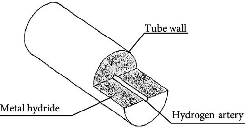
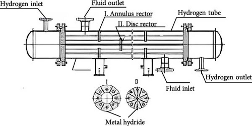
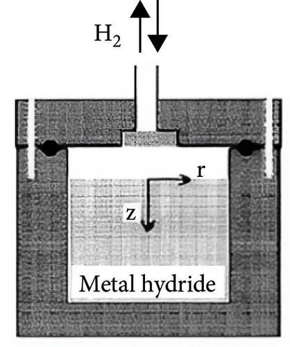
Based on their physical configurations, MHs reactors can be categorized into tubular reactors, disk reactors, and tank reactors [117, 120, 121]. As shown in Figure 9, initially, the design of marine MHs hydrogen storage reactors primarily adopted tubular or tank structures, with little consideration given to heat transfer mechanisms. However, a review of the hydrogen absorption and desorption mechanisms reveals that the width of the PCT curve plateau region is indicative of the hydrogen storage performance of MHs, which is significantly influenced by temperature. During hydrogen absorption, as temperature increases, the plateau region narrows and the gravimetric hydrogen storage density decreases. Additionally, temperature variations affect equilibrium pressure, thereby influencing the rates of hydrogen absorption and desorption reactions in MHs. Furthermore, it has been established that the hydrogen uptake and release rates in MHs reactors are typically constrained by heat transfer rates rather than the intrinsic kinetic properties of the hydrogen storage materials [122]. In other words, while the geometric configuration of MHs reactors does not directly impact the hydride formation process, it can influence hydrogen storage performance through its effect on heat transfer.
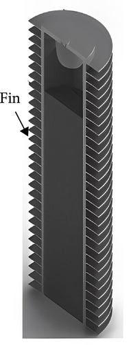
This trend is also evident in recent marine applications. Lazar et al. [123] designed a hydrogen storage tank for marine and inland shipping vessels, incorporating a heat transfer enhancer with five primary fins and five secondary fins, as illustrated in Figure 5. This optimized design enhances cooling efficiency by 46.1% and reduces refueling time by 41%. Consequently, an increasing number of researchers have begun to focus on the structural design of MHs reactors. Given the limited research and projects dedicated to the structural optimization of MHs reactors for maritime applications, this paper aims to summarize the current state of structural optimization to facilitate better application in the field of marine engineering.
4.2.1. Optimization of MHs Reactor Hydrogen Storage Performance
For the marine MHs reactor, it is imperative to ensure both the hydrogen storage capacity and the hydrogen absorption and discharge rates, which are critical design parameters. While increasing the diameter or height of the reactor can enhance hydrogen storage capacity to some extent, this approach is constrained by the limited heat and mass transfer efficiency of the MHs reaction bed. As the reactor diameter increases, maintaining rapid and complete MHs reactions becomes challenging due to insufficient heat exchange area. Therefore, optimizing the reactor to improve hydrogen storage performance is essential. This optimization primarily involves two aspects: enhancing the effective thermal conductivity of the MHs reaction bed and optimizing the structural design of the MHs reactor.
4.2.1.1. Enhance the Effective Thermal Conductivity of MHs Reaction Bed
Currently, research aimed at enhancing bed heat conduction predominantly centers on improving the thermal conductivity of the bed. The primary methods encompass: (1) insertion of high thermal conductivity solid matrices or compaction of MHs [126–135]; (2) utilization of high-porosity MHs [136–138]; and (3) incorporation of materials with high thermal conductivity [136, 137].
Owing to the micrometer-scale dimensions of the solid particles, the thermal conductivity of the MHs reaction bed is inherently low. This limitation can be mitigated by incorporating a high thermal conductivity solid matrix into the MHs reactor or by densifying the MHs. Commonly employed methods include the use of multiwave plates [126], linear substrates [127], metal fins [128–130], metal honeycomb structures [131–134], and metal foams [135, 136]. Figure 10 illustrates several typical techniques designed to enhance thermal conductivity and thereby improve the heat transfer performance of MHs reactors. Studies have demonstrated that the addition of metal fins or copper wire matrices to the reaction bed can elevate thermal conductivity from 0.1 W·m−1·K−1 to approximately 2.0 W·m−1·K−1 [128, 132, 134]. However, these approaches still present challenges in enhancing the hydrogen storage performance of the reactor: the inclusion of a solid matrix increases the overall weight, reduces hydrogen storage capacity, and may adversely affect the cycle stability of hydrogen storage materials [134].



In addition, metal foams characterized by high porosity, elevated thermal conductivity, and a large surface area relative to their small volume have found extensive application in enhancing heat transfer within MHs systems [135–137]. As illustrated in Table 5, incorporating metal foams can elevate the thermal conductivity of MHs reaction beds to over 4 W·m−1·K−1, more than doubling that of solid substrates such as those with inserted metal fins. Moreover, the inclusion of metal foam promotes a more uniform temperature distribution within the reactor [138]. Laurencelle et al. [136] investigated the impact of adding aluminum foam with a porosity of 0.9 to LaNi5 alloy on the hydrogen absorption and desorption performance of MH reactors. Their findings revealed an increase in thermal conductivity from 0.15 to 10 W·m−1·K−1, along with a 7.5-fold enhancement in hydrogen absorption and desorption rates compared to reactors without aluminum foam. Additionally, Mellouli et al. [137] conducted numerical simulations to examine the influence of metal foam on the hydrogen storage performance of MHs systems, as depicted in Figure 7. The results indicated that the addition of metal foam reduced the time required to achieve 90% hydrogen storage capacity by 60% compared to reactors without metal foam. However, the primary challenges associated with this technology include high contact thermal resistance between alloy powders and metal foam; difficulties in achieving powder densification within the metal foam; and higher costs that hinder commercialization.
| Metal alloy | Augmentation techniques | ETC of metal alloy | ETC with augmentation | Ref |
|---|---|---|---|---|
| LaNi4.61Mn0.26Al0.13 | Copper fins | 0.61 | 1.6 | [128] |
| LaNi5 | Copper fins and flakes | 0.1 | 1.36 | [129] |
| LaNi5 | Copper wire matrix | 0.1 | 0.2–2.5 | [132] |
| TixCr2-yMny | Aluminum honeycomb | — | 2–3.6 | [141] |
| LaNi5 | Aluminum foam | 0.1 | 10 | [135] |
| MmNi4.5Al0.5 | Aluminum foam | — | 4 | [142] |
| ZrCo | Copper foam (98% porosity) | 0.82 | 4.95 | [136] |
| Copper foam (95% porosity) | 12.15 | |||
| Copper foam (90% porosity) | 24.15 | |||
| LaNi5 | Compacts with aluminum | 0.5 | 8–23 | [143, 144] |
| LaNi4.85Sn0.15 | Expanded graphite MH compact | — | 19.5 | [145] |
| LaNi4.5Co0.5 | Carbon nanotube synthesis | — | 10 | [146] |
| LaNi5 | Copper coating on MH particles | 0.22 | 5 | [144] |
| LaNi5 | Cu encapsulation þ Sn binder | 0.1 | 2.9–6.2 | [147] |
Compacting metal powder can significantly enhance its thermal conductivity and improve hydrogen storage performance [140]. Additionally, this process increases the apparent density of MHs, thereby enabling higher hydrogen storage capacity. Manai et al. [148] performed numerical simulations on compacted MHs powder to investigate its hydrogen storage characteristics. Their results demonstrated that thermal conductivity increased from 1 to 1.221 W·m−1·K−1, hydrogen storage capacity improved by approximately 1.3 times and the hydrogen absorption and desorption rates were nearly eightfold higher compared to uncompacted powder materials. Furthermore, blending alloy powders with high thermal conductivity materials such as carbon, expanded graphene, or aluminum alloy corundum powder can further enhance the thermal conductivity of the MHs reaction bed, thus improving the overall hydrogen storage performance of the reactor. Ron, Bershadsky, and Josephy [143, 149] investigated the formation of porous MHs through the compaction and sintering of mixed Al and LaNi5 alloy powders, examining the impact of varying aluminum powder mass fractions on thermal conductivity. Their findings revealed that the thermal conductivity of the MHs reaction bed increased from 8 to 23 W·m−1·K−1 as the aluminum powder mass fraction ranged from 0.1 to 0.5. However, the high-pressure requirements for sintering led to thermodynamic losses in material properties. To address this issue, Kim et al. [144] developed a novel composite hydrogen storage material by copper-coating LaNi5 and cold-pressing it with a low-melting-point metal binder, achieving a thermal conductivity enhancement of 5 W·m−1·K−1. Nevertheless, incorporating metallic materials into MHs can increase heat loss and reduce hydrogen storage capacity. Moreover, compacting MHs decreases porosity and permeability, thereby, limiting heat transfer within the reaction bed. Adding carbon or graphene to compacted MHs can mitigate these challenges. Madaria and Anil Kumar [150] evaluated the heat transfer performance of three types of MHs reaction beds: MHs powder, MHs mixed with graphene fibers, and MHs mixed with graphene powder embedded in copper wire. Their results indicated that graphene fibers enhance both heat transfer and hydrogen storage properties of MHs. Sánchez, Klein, and Groll [145] compared the effects of adding aluminum foam versus expanded graphene on the thermal conductivity of MHs. They found that the expanded graphene reaction bed exhibited higher thermal conductivity (>19 W·m−1·K−1) compared to the foamed aluminum reaction bed (8 W·m−1·K−1). Additionally, expanded graphene offers a cost advantage over metal foam.
4.2.1.2. Optimization of MHs Reactor Structure
From a macroscopic perspective, the heat transfer mechanisms within an MHs reactor primarily encompass heat conduction inside the reactor and convective heat transfer between the reactor wall and its surrounding environment. Despite enhancing the thermal conductivity of the bed material, relying solely on natural convection in the surrounding environment, particularly in relatively enclosed spaces such as cabins, cannot fulfill the rapid heat transfer requirements of MHs reactors. Consequently, it is imperative to optimize the reactor structure. Common optimization strategies include incorporating internal cooling structures (e.g., internal fins and internal heat exchange tubes), external cooling structures (e.g., external fins and external cooling water jackets), and integrating phase change materials (PCMs) for enhanced thermal management.
4.2.1.2.1. External Cooling Structure: External Fins and External Cooling Water Jackets. External fins enhance heat transfer performance through an increased contact area with the external environment or heat transfer fluid. The outer water jacket augments heat exchange between the reactor and its surroundings by elevating the external convection heat transfer coefficient.
Jemni, Nasrallah, and Lamloumi [151] investigated the design of a conventional tank hydrogen storage reactor. During the initial stage of hydrogen absorption, which is an exothermic reaction, the MHs near the inner wall of the tank can be effectively cooled. However, heat dissipation from the central region is challenging, leading to rapid temperature increases and significant temperature gradients within the reactor. This uneven temperature distribution results in suboptimal hydrogen storage efficiency. Building on this work, Kaplan [152] examined three reactors of identical nominal size but with different heat transfer structures: traditional tank reactors, reactors with external fins, and reactors with external cooling water jackets, as illustrated in Figure 11. Under identical operating conditions, the researchers conducted experimental studies on the hydrogen absorption and desorption performance of these reactors and calculated the effective heat transfer coefficients for each reactor based on their findings. The results indicate that the effective heat transfer coefficients for the three reactors are 5.5, 35, and 113 W·m−2·K−1, respectively. Further analysis of the temperature distribution reveals that the reactor equipped with an external cooling water jacket exhibits superior heat transfer performance, significantly enhancing the reactor’s heat exchange efficiency and optimizing hydrogen storage capabilities. However, the positive impact of the external cooling fluid is not sustained indefinitely. Askri et al. [153] investigated the influence of external fins on hydrogen absorption performance under both natural and forced convection heat transfer conditions. Their findings demonstrate that, under natural convection, the hydrogen absorption rate of reactors with external fins is approximately 10% faster compared to those without fins. In contrast, under forced convection, the presence of external fins does not confer any significant advantages. This suggests that when considering methods to increase the outer surface area of the reactor for enhanced heat transfer, it is crucial to evaluate whether incorporating external forced convection structures or controlling the flow rate of the external heat transfer fluid would be more cost-effective, thereby, avoiding unnecessary expenses.

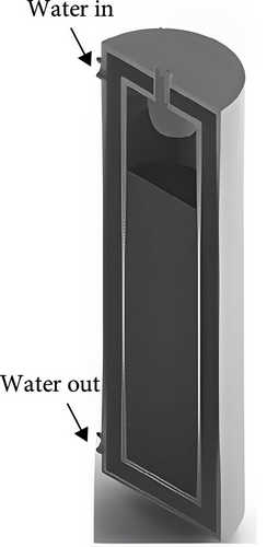

In addition, Askri et al. [153] modified the external heat transfer structure to an internal straight tube heat transfer design. Under identical reactor shape, size, MHs type, filling amount, and operating conditions, the time required for the reactor with the internal straight tube heat transfer structure to achieve 90% hydrogen filling was reduced by 56% compared to the externally cooled reactor. This clearly demonstrates that the thermal management efficiency of internal heat transfer significantly surpasses that of external heat transfer. Subsequent studies have predominantly focused on enhancing internal heat transfer methods. Researchers have designed and investigated various approaches to improve internal heat transfer, including internal fin/honeycomb structures, straight tube heat transfer, spiral tube heat transfer, and microchannel heat transfer, addressing issues such as inadequate external heat transfer performance, limited hydrogen storage capacity per unit, a large number of hydrogen storage units, and complex Anlu valve systems.
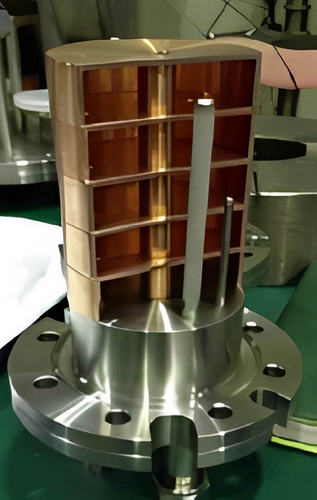
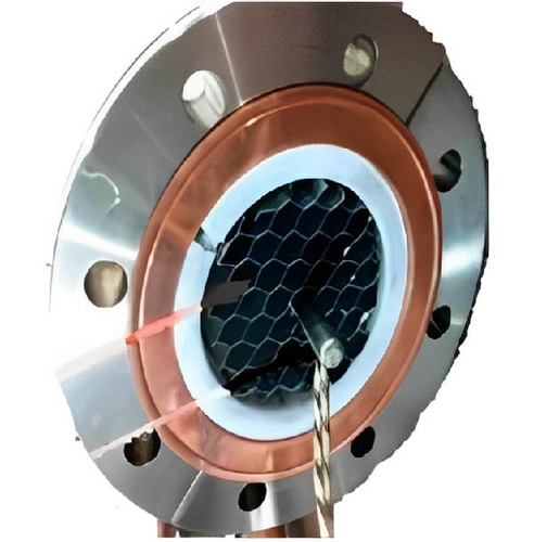
4.2.1.2.2. Internal Cooling Structures: Internal Fins and Internal Heat Exchange Tubes. Unlike external fins, the internal fin structure theoretically enhances the heat transfer area within the reaction bed and increases the local effective thermal conductivity of the reaction bed. Weckerle, Bürger, and Linder [154] developed a novel flat-plate MHs reactor, as illustrated in Figure 12a. The multilayer cross-plate heat exchange structure inside the reactor reduces the overall heat exchange path length, thereby accelerating the heat transfer rate. Experimental results indicate that this reactor can significantly reduce the reaction cycle time. However, this design is primarily suitable for small-scale, integrated, and compact applications, enabling rapid response to hydrogen absorption and desorption requirements. Corgnale et al. [133] introduced a new honeycomb-finned MHs reactor, featuring an internal heat exchange structure with a regular hexagonal arrangement of thermal fins, as shown in Figure 12b. A 100 W electric heater placed at the center of the honeycomb structure provides the necessary heat for hydrogen desorption. Within a short period, the 0.5L container can release approximately 45% of its hydrogen content.
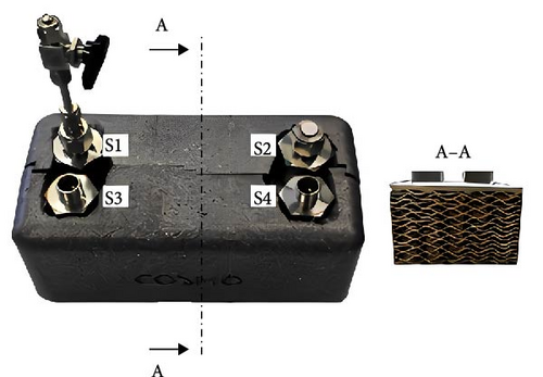
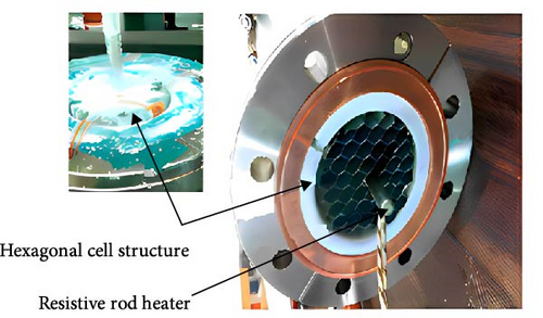
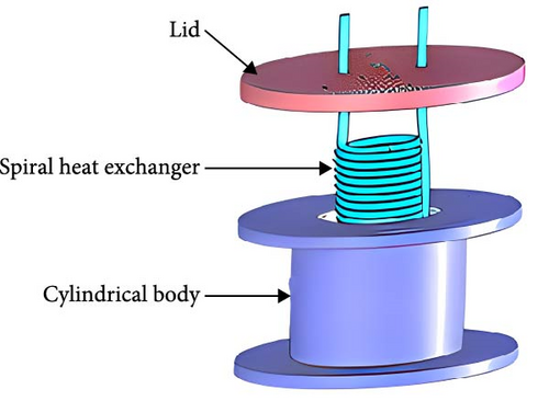
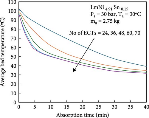
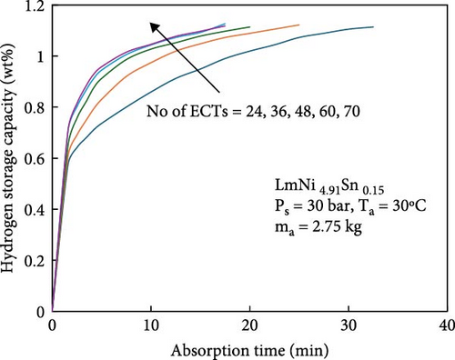
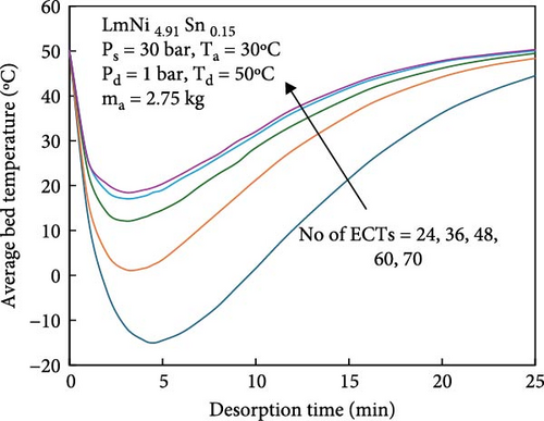
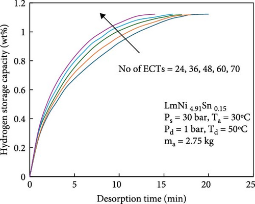
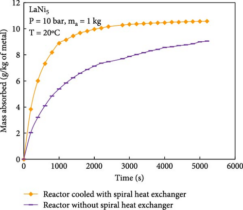
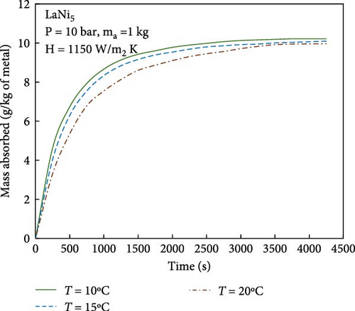
During the hydrogen absorption and desorption process, the cooling extent between the reactor’s outer wall and the core region varies. The alloy near the heat exchange device is more significantly affected, leading to localized temperature extremes that negatively impact the heat transfer mechanism and overall performance of MHs reactors. Consequently, the number, shape, and size of heat exchange tubes are critical parameters influencing MHs reactor performance. Anbarasu, Muthukumar, and Subhash [155] employed a combination of numerical simulation and experimentation to investigate the effect of varying the number of internal heat pipes on hydrogen storage performance in MH reactors, as illustrated in Figure 13a. Their findings, presented in Figure 14, indicate that increasing the number of internal heat pipes from 24 to 70 significantly enhances heat transfer efficiency and reduces the required hydrogen storage time by nearly 30%. However, beyond a certain threshold, further increases in the number of heat pipes yield diminishing returns in terms of heat exchange performance improvement and may even reduce hydrogen storage capacity. Therefore, while increasing the number of internal heat pipes can substantially decrease thermal resistance and improve heat transfer, optimizing this number during the design phase is crucial to ensure that hydrogen storage capacity remains unaffected. Mellouli et al. [156] introduced an MHs reactor equipped with a built-in spiral heat exchange tube, as illustrated in Figure 13b. They conducted experimental studies on hydrogen absorption and desorption processes. The results are presented in Figure 15. Under identical operating conditions, the hydrogen storage time for the reactor without the built-in spiral heat exchange tube was found to be five times longer compared to the reactor with the built-in spiral heat exchange tube. Furthermore, the coolant temperature significantly influenced the hydrogen storage time. Tong et al. [157] investigated the impact of different heat exchange tube configurations (no heat exchange structure, internal straight tube, and internal spiral tube) on the performance of the MHs reactor under the same reactor volume. Their findings revealed that the time required to reach 90% hydrogen storage capacity was 1531, 1012, and 419 s, respectively. The spiral tube heat transfer structure demonstrated superior hydrogen storage performance due to its larger heat exchange area compared to the straight tube. Additionally, a lower coolant temperature reduced thermal resistance, thereby, increasing the effective heat transfer coefficient of the reactor and enhancing both hydrogen absorption and desorption efficiency.
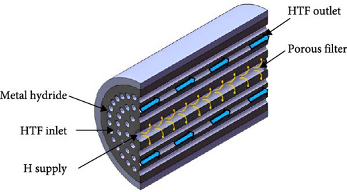
For the reactor with internal heat exchange channels, heat exchange between the heat transfer fluid and the bed primarily occurs via the wall surface. To enhance heat transfer between the heat exchange fluid tube and the reaction bed, high thermal conductivity fins can be integrated into the heat exchange channel. This not only shortens the distance for heat transfer from within the bed to the heat exchange tube but also improves the efficiency of heat removal from the reactor through the heat exchange fluid. For instance, Sekhar et al. [158] investigated the effects of four different cooling configurations on the hydrogen absorption performance of MHs reactors under identical reactor volumes using numerical simulations, as illustrated in Figure 16. The configurations included an internal cooling tube, an internal spiral coil, and external heat exchangers with or without internal fins. The results indicated that the hydrogen absorption performance, from lowest to highest, was cooling tube < external cooling without fin < spiral coil < external cooling with internal fin. This demonstrates that the cooling configuration significantly influences the performance of MHs reactors. To further investigate the impact of fin parameters on heat transfer and hydrogen absorption/desorption performance, Gupta and Sharma [159] conducted a parametric study by varying the number, height, and thickness of fins, ultimately determining the optimal structural design. Their findings revealed that the optimal fin structure comprised 12 fins, each with a height of 12 mm and a thickness of 2 mm. Compared to conventional designs, this optimized configuration reduced the maximum temperature rise by 22.3 K during hydrogen absorption and by 6.8 K during hydrogen desorption. These results highlight that appropriate fin parameter design can substantially improve the reactor’s heat transfer performance and enhance hydrogen absorption efficiency.
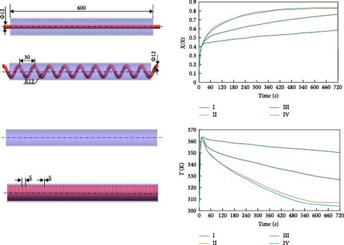
In recent years, the microchannel heat transfer structure reactor has emerged as a research hotspot aimed at maximizing the heat transfer efficiency of internally displaced hot channels. For the straight-tube microchannel MHs reactor (MCR) described above and illustrated in Figure 17a, several notable drawbacks have been identified: First, during the initial stages of hydrogen absorption, the reactor bed experiences a sharp temperature rise, leading to significant thermal stress within the MCR. This stress can cause bending and deformation of the straight tube, potentially resulting in the separation of solder joints. Second, some MHs expand by over 20% during hydrogen absorption [121], which may exert excessive pressure on the straight tube and welded sections of the MCR, leading to potential damage and instability or even hazardous conditions over prolonged periods. Additionally, the miniature straight tube’s small diameter results in a relatively limited heat transfer area and operational adjustability. Consequently, an increasing number of researchers have focused on developing innovative microchannel reactors to mitigate these adverse effects. The novel spiral MCR (SMCR) proposed by Li et al. [160], depicted in Figure 17b, significantly enhances the reactor’s thermal performance and hydrodynamic characteristics through its distinctive structural design. Research findings indicate that the spiral tube design not only effectively alleviates stress induced by temperature changes and volume expansion but also increases turbulence intensity and heat transfer efficiency. In the parameterization study of the SMCR, researchers optimized the spiral tube’s structural design, determining the optimal parameters: a spiral tube radius of 2.2 mm, an axial pitch of 5 mm, a main radius of 5.5 mm, and three tubes. Moreover, the radial projection area of the heat exchange tube was identified as a critical factor influencing heat transfer. To address this issue, Wang et al. [161] introduced a novel radiating tube–based MCR (RMCR) with a water jacket, inspired by the tree trunk bionic structure, as illustrated in Figure 17c. Through numerical simulations, the researchers performed parametric studies on various design parameters, including dispersion number, main pipe radius, branch pipe radius, axial pitch, and main pipe center distance. The optimal structural design was determined to be: three dispersion numbers, a main pipe radius and branch pipe radius of 2 mm, an axial pitch of 5 mm, and a main pipe center distance of 8.5 mm. The results indicate that the RMCR reduces hydrogen absorption time by 54% and hydrogen release time by 20%. Sensitivity analysis revealed that the wheelbase and main pipe center distance are the most critical structural parameters, which should be prioritized for optimization in practical engineering applications. Building on this foundation, the team proposed a new branch tubular MCR (BMCR) with a water jacket, based on the vein bionic structure, as shown in Figure 17d. By optimizing the number of branches and the center distance of branch points, the final design includes three branches and a branch point center distance of 8.5 mm, while maintaining the previously determined optimal main pipe radius, branch pipe radius, axial pitch, and main pipe center distance. The BMCR reduces hydrogen absorption time by 13% and hydrogen release time by 16% and achieves a more uniform reactor wall temperature distribution, thereby enhancing overall reactor performance. This research highlights the integration of structural design and fluid dynamics, providing a crucial theoretical foundation and practical guidance for future reactor development.


Further studies on the structural optimization of MHs reactors are summarized in Table 6. In summary, the primary driving force behind the evolution of MHs reactor structures is to enhance hydrogen storage capacity while ensuring intrinsic safety. Additionally, improvements in thermal management aim to optimize hydrogen absorption and desorption performance. Currently, MHs reactors are trending toward microheat transfer channel structures that offer superior heat transfer efficiency. However, it is crucial to note that beyond addressing heat transfer challenges, frequent hydrogen absorption and desorption cycles can cause damage to the reactor. Moreover, the materials used in MHs reactors must withstand the volumetric changes associated with hydride formation, maintain mechanical integrity without degradation, and prevent internal material from becoming powdered during hydrogen absorption and desorption processes.
| S. no. | Study | MH alloy | Heat transfer structure | Thermal conductivity enhancement technique | Significant results | References |
|---|---|---|---|---|---|---|
| 1 | Three-dimensional modeling and simulation of hydrogen desorption in MH hydrogen storage vessels | LaNi5 | NA | NA | As the reaction progresses, the difference in the degree of cooling between the outer wall and the central area of the tank will lead to uneven distribution of internal temperature and reaction rate | [162] |
| 2 | Experimental comparison on heat transfer-enhancing component of MH bed | ZrCo | Cooling fin structure | Copper foam/fins | The copper foam bed takes 20% less time to absorb hydrogen than the copper fin bed | [163] |
| 3 | Experiments on solid state hydrogen storage device with a finned tube heat exchanger | LaNi5 | Copper fins | The shortest charging time found is 490 s for the absorption capacity of 1.2 wt% at a supply pressure of 15 bar and cooling fluid temperature and velocity of 288 K and 1 m/s, respectively | [164] | |
| 4 | Optimization of internal heat exchangers for hydrogen storage tanks utilizing MHs | LaNi5 | Copper fins (transverse and longitudinal) | The optimal designs for both the transverse and longitudinal fin designs point toward closely spaced, small cooling fluid tubes | [165] | |
| 6 | Parametric studies on MmNi4.7Fe0.3 based reactors with embedded cooling tubes for hydrogen storage and cooling application | MmNi4.7Fe0.3 | Cooling tube structure | Cooling tubes | Increasing the number of embedded heat exchange tubes can shorten the time of hydrogen absorption and discharge | [166] |
| 9 | Hydrogenation behavior in rectangular MH tanks under effective heat management processes for green building applications | LaNi5 | Cooling tubes | Compared with the single-row and mixed-row reactors, the multi-row rectangular hydrogen storage device has excellent hydrogen absorption and discharge performance | [167] | |
| 10 | Improvement in hydrogen desorption performances of magnesium-based MH reactor by incorporating helical coil heat exchanger | Mg2Ni | Cooling tubes | The reactor with helical coil heat exchanger offers greater heat and mass transfer than reactors with straight tube and finned tube | [168] | |
| 12 | Experiments on a MH–based hydrogen storage device | MmNi4.6Fe0.4 | Cooling fin coupling cooling tube | Copper fins + cooling jacket | Cold fluid temperature is found to have a significant effect on hydrogen storage capacity at lower supply pressures | [169] |
| 13 | Experimental and comparative study of MH hydrogen tanks | LaNi5 | Copper fins + cooling tube | The coil heat exchanger is more efficient than cooling tubes | [170] | |
| 15 | Performance simulation and experimental confirmation of a mini-channel MHs reactor | LaNi5 | Capillary tube bundle | Compared with the traditional reactors, such as tubular reactors and disc reactors, the mini-channel reactor has some obvious advantages, therefore can be recommended for applications | [171] | |
| 16 | Optimization of heat transfer device and analysis of heat and mass transfer on the finned multitubular MH tank | LaNi5 | Copper fins + multitubular | The increase in the fin radius, thickness, and number will result in a decrease of thermal resistance from the analysis results of RT and Rh, f. The fin number has the most significant positive effect on the absorption reaction rate | [172] | |
4.3. Operating Condition Optimization
The architecture of the MHs reactor plays a crucial role in determining its hydrogen absorption and desorption performance. Enhancing the reactor’s structure can significantly improve both heat transfer efficiency and hydrogen absorption/desorption capabilities. Nevertheless, for reactors with a fixed structure, other critical factors influencing the hydrogen storage system’s performance include external hydrogen supply pressure, characteristics of the heat transfer fluid (such as temperature, flow rate, concentration, and type), thermal conductivity of solid and liquid phases, porosity of porous media materials, and MH particle size, among other operational parameters [173].
Yuan, Bao, and Huang [174] employed a numerical simulation approach to investigate the impact of hydrogen supply pressure and heat exchange fluid temperature on the heat transfer performance and hydrogen absorption reaction characteristics of the reactor. Their findings indicated that reducing the hydrogen supply pressure led to a decrease in both the reaction rate and the mean bed temperature. Specifically, when the hydrogen supply pressure was reduced to 0.6 MPa, the reaction rate significantly diminished. Additionally, increasing the temperature of the heat exchange fluid decreased the heat transfer temperature difference, thereby reducing the reaction rate; at 323 K, the reaction became nearly infeasible. Similarly, Wang, Zhang, and Yao [175] conducted a numerical simulation study to examine the effects of thermal oil inlet temperature and hydrogen supply pressure on the hydrogen storage reaction rate. They observed that as the heat transfer oil inlet temperature increased from 548 to 573 K, the reaction rate rose by 158%. However, further increasing the temperature from 573 to 648 K resulted in a 55% reduction in the reaction rate. Moreover, raising the hydrogen supply pressure from 0.5 to 3 MPa shortened the hydrogen storage time by approximately 81.8%, while increasing the temperature by 65 K. These results suggest that there is an optimal reaction temperature for hydrogen storage and heat release processes, with excessively high or low temperatures potentially diminishing reaction efficiency. Furthermore, increasing the hydrogen supply pressure can enhance the reaction rate but also causes a rise in bed temperature. During hydrogen absorption, the time required for reactor saturation increases with higher heat transfer fluid temperatures due to the reduced temperature difference between the reaction bed and the heat transfer fluid.
Conventional heat transfer fluids, such as water, engine oil, ethylene glycol, and mineral oil, have been widely utilized. However, numerous studies indicate that these traditional media exhibit low cooling efficiency due to their limited heat transfer capacity. To address this issue, Choi et al. [176] introduced the concept of suspending NPs in base fluids, thereby enhancing the thermal properties of conventional coolants. This innovation significantly increased the surface area and heat transfer coefficient compared to the base fluid alone, opening a new research direction in heat transfer. Common materials for NPs include metals, metal oxides, carbides, and carbon nanotubes. In a recent study, Kanti et al. [177, 178] investigated the impact of various heat transfer fluids and their concentrations on heat transfer performance and reaction rates in MH hydrogen storage reactors. Specifically, they examined water and its nanofluids (NFs), including graphene oxide (GO), GO-SiO2 (50:50), GO-TiO2 (50:50), and Al2O3. The findings revealed that a 1 vol% concentration of GO NF demonstrated superior heat transfer characteristics compared to water and other NFs. Moreover, it reduced the reaction time required to achieve 90% hydrogen storage capacity by 61.7% under identical conditions. The hydrogen storage efficiency was found to be positively correlated with the concentration of NFs.
Yuan, Bao, and Huang [174] studied the hydrogen absorption and emission properties of hydrogen storage materials under different thermal conductivity (from 0.6 to 1.4 W·m−2·K−1). The results show that when the thermal conductivity is high, the heat inside the bed can be quickly transmitted through the bed to the heat exchange tube, which makes the temperature distribution inside the bed more uniform, thus, significantly improving the reaction rate. However, when the thermal conductivity reaches or exceeds 1 W·m−1·K−1, this enhancement effect is no longer obvious, so it can be inferred that there is an optimal thermal conductivity to achieve the best hydrogen absorption and discharge performance.
In summary, the heat generated during the hydrogen absorption process can reduce the reaction rate. Therefore, it is crucial to rapidly dissipate this heat from within the reactor. To enhance the heat transfer efficiency and the reaction rate of the hydrogen storage system, developing a heat transfer fluid with superior thermal conductivity is recommended. Properly adjusting parameters such as the concentration, initial temperature, and flow rate of the heat transfer fluid can significantly improve the thermal management efficiency of the reaction. Moreover, bed thermal conductivity is an essential parameter to consider when designing hydrogen storage devices. By controlling factors such as hydrogen supply concentration, MH particle size, and porosity, the effective thermal conductivity of the bed can be optimized, thereby enhancing the overall performance of the hydrogen storage system.
4.4. Thermal Management System
4.4.1. Thermal Coupling System (TCS) of MHs Hydrogen Storage and PEMFC
The power system of hydrogen-powered ships typically comprises MHs hydrogen storage unit and PEMFC. Under specific operating conditions, the MHs hydrogen storage unit supplies hydrogen to the PEMFC, which subsequently converts hydrogen energy into electrical energy [12]. As previously noted, the hydrogen storage process in MHs is characterized by significant enthalpy changes and substantial thermal effects. Without effective thermal management, the temperature of the hydrogen storage unit may experience abrupt fluctuations, severely impacting its reaction rate and cycle stability. Additionally, during PEMFC operation, approximately 60% of hydrogen energy is converted into heat energy due to thermodynamic irreversibility. To prevent fuel cell overheating, efficient thermal management is essential [176–178]. Considering the complementary thermal requirements between the MHs hydrogen storage unit and PEMFC (i.e., the heat required for hydrogen venting from the MHs reactor can be supplied by PEMFC waste heat), integrating these components can eliminate the need for a separate and costly thermal management system. Consequently, a coupled TCS for MHs and PEMFC has been developed. This system ensures stable operation of both units, reduces energy consumption, enhances energy efficiency, and lowers costs. Based on control methods, TCS can be categorized into passive and active types. Passive methods include direct heat transfer, heat pipe heat transfer, and radiative heat transfer, while active methods encompass air-cooled and liquid-cooled heat transfer, as illustrated in Figure 18 [179].
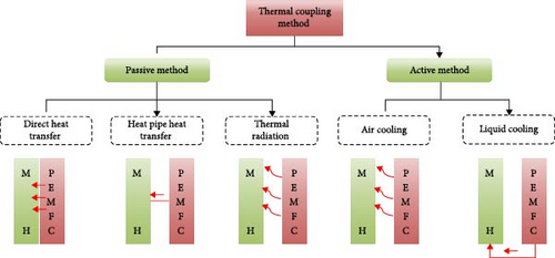
From the perspective of heat transfer, liquid-cooled systems exhibit superior performance compared to air-cooled systems due to the significantly higher heat transfer coefficient of coolants relative to air [180–184]. Considering the operational environment of marine vessels, the implementation of liquid cooling for coupling MHs and PEMFC on ships is particularly suitable, given the abundant availability of seawater resources. Specifically, a heat exchange channel between the PEMFC and the MHs reactor is established, with coolant circulated through this channel by a pump, as illustrated in Figure 16. It should be noted that fluctuations in the ship’s power demand can result in inadequate heat transfer by the MHs reactor, leading to reduced hydrogen release from MHs, which in turn decreases the power output and available heat from the PEMFC. Accumulated deviations from optimal performance can compromise system control, hinder the achievement of control objectives, and reduce overall system efficiency. Therefore, the TCS necessitates a rapid response and high-precision control strategy.
Tong et al. [185] developed control models for the PEMFC, MHs reactor, and liquid cooling system of inland vessels using the Matlab/Simulink software platform. By adjusting the opening of the PEMFC outlet valve, they controlled the fluid temperature entering the MHs reactor, thereby, indirectly regulating the hydrogen discharge rate of the MHs reactor to achieve precise control of PEMFC power output. The findings indicate that valve opening is a critical parameter in liquid-cooled TCS and adjusting this parameter significantly enhances system performance. To further improve the accuracy and response speed of the control model, Cavo et al. [42] utilized ZEUS, a zero-carbon emission ship in Italy, to establish a control model for a seawater-cooled heat transfer TCS. As illustrated in Figure 19, the model comprises two control loops: the first loop adjusts the bypass valves V1A/B and V2A/B to regulate the fluid temperature at the PEMFC outlet; the second loop controls the WGHE outlet temperature by adjusting the V0 bypass valve. The system employs the Ziegler–Nichols oscillation method to fine-tune two PI controllers. The results demonstrate that the hydrogen demand was effectively met during the voyage, allowing the ship to maintain a cruising speed of 6 knots for 7 h.
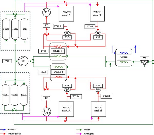
In the simulation research of thermal management system, the number of control variables is usually simplified to 1 or 2 in order to facilitate the application of error-giving control algorithms (such as PI and PID control). While this approach is effective to a certain extent, in more complex thermal management systems, single or two-variable control may not be able to meet the diverse and refined needs [186]. Model predictive control (MPC) is gradually showing its great potential, especially in practical applications involving multiple components and multiple control objectives. By utilizing the dynamic model of the system, MPC can optimize the current control input at each control moment, thus coordinating the behavior of multiple components within a predicted time window [187, 188].
4.4.2. MHs Reactor Coupled PCMs
As previously discussed, the hydrogen storage process is associated with significant thermal effects, which can adversely impact the reaction efficiency. Consequently, Lutz, Linder, and Bürger [189] introduced the concept of adiabatic storage. This approach aims to utilize the heat generated during the hydrogen absorption phase to compensate for the energy required during the hydrogen release phase, thereby, achieving mutual energy compensation between the two processes. Among current heat storage methods, latent heat storage via PCMs is prominent [190]. PCMs store or release heat through melting or solidification at nearly constant temperatures, exhibiting high energy storage density, minimal phase change temperature differences, stable chemical properties, and cost-effectiveness, making them widely applicable in thermal management systems [191].
Previous research has demonstrated the feasibility of integrating MHs with PCMs. Ben Mâad, Askri, and Ben Nasrallah [192] developed a two-dimensional transient mathematical model to predict the coupled heat and mass transfer between an MHs bed and an external PCMs jacket, as illustrated in Figure 20a. The model was validated against experimental results, confirming the viability of storing heat released during hydrogen desorption in the PCMs and subsequently supplying it back to the MHs tank during hydrogen absorption. Additionally, the study revealed that the thermal conductivity and melting enthalpy of the PCMs significantly influence hydrogen storage performance. Specifically, increasing the thermal conductivity to 5 W·m−1·K−1 notably enhances hydrogen absorption efficiency, while reducing the melting enthalpy to 100 kJ·kg−1 decreases hydrogen storage capacity by 16%. Key challenges include the limited heat transfer area and the relatively low thermal conductivity of PCMs, typically ranging from 0.2 to 0.7 W·m−1·K−1.
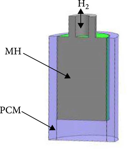
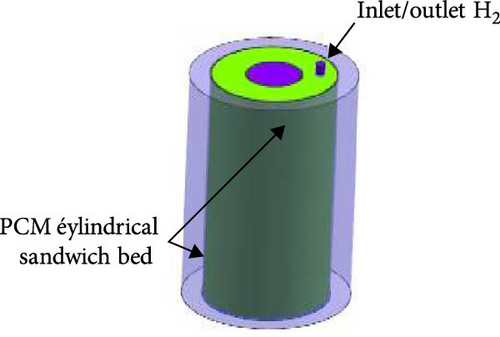
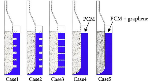

To address the aforementioned limitations, the relative specific surface area of MHs and PCMs was enhanced by optimizing the reactor structure of MHs. Rizzi et al. [193] proposed incorporating an additional layer of PCMs annulus within the MHs reactor, as illustrated in Figure 20b. The results demonstrated that this modification reduced the hydrogen absorption and desorption times by 81.5% and 73%, respectively, compared to the MHs reactor with a single layer of PCMs on the outer wall. Furthermore, Yao et al. [194] developed a coupled thermal management model for a PCMs jacket and MH reactor featuring various fin structures, utilizing paraffin wax as the PCMs material, as depicted in Figure 20c. The results demonstrate that the hydrogen storage reactor integrated with PCMs can achieve high hydrogen storage efficiency without utilizing any external heat source, thereby, enhancing the heat exchange area between PCM and MHs, which facilitates efficient heat storage and release. Given the low thermal conductivity of PCM, it can be combined with metal foam or expanded graphene to form a composite PCMs with enhanced thermal conductivity. The research team optimized the model by incorporating expanded graphene into the PCMs, resulting in an improvement in hydrogen storage efficiency from 69% to approximately 72%. Shrivastav et al. [195] introduced copper fins within both MHs and PCMs and investigated the impact of fin quantity, thickness, and pitch on the hydrogen absorption rate.
In the optimization of MHs reactor structure, an additional PCMs/MHs heat transfer channel was introduced based on the existing MHs/PCMs configuration. Mahmoodi and Rahimi [196] embedded various structural forms of PCM heat exchange tubes (including spherical shells, hexagonal tubes, and cylindrical tubes) within the MHs reactor, using sodium nitrate (NaNO3) as the PCM while retaining the external PCMs jacket, as illustrated in Figure 20d. The findings indicate that the geometric shape of the PCMs heat exchanger significantly influences system performance, particularly with the cylindrical phase-change heat exchanger achieving a 58% improvement in hydrogen absorption time compared to the basic configuration. However, this approach may reduce the hydrogen storage capacity of the MHs device to some extent. Ye et al. [197] proposed a novel PCMs–based MHs reactor array layout, incorporating a high specific surface area heat transfer interface. They observed that increasing the number of array units substantially increased the heat transfer area, leading to a significant doubling of hydrogen absorption efficiency in a seven-unit array reactor compared to a traditional single-unit reactor under the same MHs volume. Nevertheless, this effect has limitations, necessitating optimal utilization of heat storage performance within the confined PCMs substrate. Additionally, increasing system pressure can enhance reaction dynamics and widen the temperature difference between PCMs and MHs, thereby, improving heat transfer and reaction efficiency.
5. Conclusion
Based on the above review contents, we summarized the current basic problems, program problems and direction problems of marine MHs hydrogen storage technology, as shown in Figure 21. The basic problems include reaction rate, hydrogen storage capacity, heat transfer efficiency, and cycle stability; the solution problems include alloying and nano and catalyst, high pressure and atmospheric pressure (relative), high temperature and low temperature (relative), internal cooling structure and external cooling structure and mixed cooling structure, high flow rate heat transfer and low flow rate heat transfer; directional issues include efficiency, capacity, heat transfer, safety, and cost. The above issues, academic heat from high to low, industrial importance from high to low.
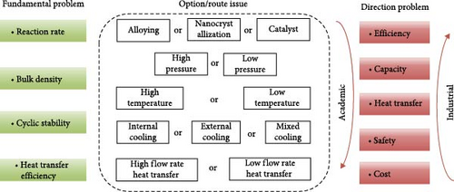
- •
Proposing new synthesis routes for MH hydrogen storage materials and improving the characterization techniques of MH storage materials should be future development goals. Methods to enhance the hydrogen storage performance of MHs include alloying, adding catalysts, and nanostructuring. Among these, alloying and nanostructuring technologies are relatively mature. The introduction of metal-based catalysts and carbon composites can effectively improve the kinetics of hydrogen absorption and desorption in the materials. However, these approaches are still in the theoretical and experimental stages, especially concerning the selection of precious and nonprecious metals and have not yet been widely implemented in engineering applications.
- •
Optimizing the structure of MHs reactors in combination to improve heat exchange performance and enhance hydrogen storage capacity: For example, many current studies aim to improve the overall performance of MHs reactors by increasing the surface area-to-volume ratio and enhancing the convective heat transfer pathways within the reactor. However, there is a lack of research focused on the combinatorial optimization of these methods. Additionally, as MH reactors evolve towards microchannel structures, there is a tendency to overlook the cyclic stability of hydrogen storage materials and the structural integrity of the reactor. This will be an important direction for future research.
- •
Improving the operating conditions of MHs reactors: For a reactor with a defined structure, operating parameters such as hydrogen supply pressure, temperature, heat transfer fluid characteristics, and effective thermal conductivity of the bed are crucial factors that influence the reaction rate and storage capacity of the hydrogen storage system. Therefore, it is particularly important to reasonably regulate the operating conditions of the reaction process (especially the development of high-performance heat transfer fluids) and to predict their effects (developing predictive models for effective thermal conductivity).
- •
Analyzing the dynamic coupling characteristics between MHs reactors and PEMFCs should also be a key focus of future research. By establishing simulation or experimental models of a coupled solid state hydrogen storage PEMFC power system, a detailed analysis of the impact of structural parameters, operating parameters, and other factors on the system’s power can be conducted. This will enable more stable applications in vehicles, ships, aircraft, and other fields in the future.
- •
The analysis of the thermal and dynamic coupling characteristics between MHs reactors and PEMFCs should also be a key focus of future research. By effectively utilizing the thermal complementarity between MHs and PEMFC, it is crucial to develop MPC algorithms with high response speed and accuracy to ensure the stability and precision of the hydrogen supply rate from the MHs and the power output of the PEMFC, thereby meeting the actual navigation requirements of vessels.
- •
In addition, the use of computational tools in the research and development of materials and systems should be more widespread. In terms of model prediction for energy storage and heat transfer issues, machine learning methods (such as genetic expression programming (GEP), adaptive neuro-fuzzy inference systems (ANFIS), Gaussian process regression (GPR), boosted regression trees (BRT), AdaBoost, XGBoost, and genetic algorithms) clearly serve as viable alternatives to more traditional methods like experimentation and simulation for large volumes of material and system data. AI management systems will be widely applied in hydrogen storage systems, enabling cloud computing and decision-making implementation.
Conflicts of Interest
The authors declare no conflicts of interest.
Author Contributions
Chaohe Chen: conceptualization, validation, formal analysis, investigation, supervison, and writing–review and editing. Yingkai Dong: conceptualization, validation, formal analysis, investigation, writing–review and editing. Mengjie Jiang: investigation, resources, and visualization. Lianbin Zhang: investigation, resources, and visualization.
Funding
This research is supported by the Key Area Research and Development Program of Guangdong Province, China (Grant 2021B0707040002).
Open Research
Data Availability Statement
All data generated or analyzed during this study are included in this published article.


