Up-to-Date Review on Flat-Plate Solar Hybrid Photovoltaic Thermal Systems: Absorber Designs and Fabrication Materials
Abstract
Photovoltaic (PV) technology is generally perceived as well-developed but suffers a drop in performance at high temperatures. Faced with this problem, researchers are turning to PV thermal (PVT) systems, which integrate electricity production and thermal energy. Flat-plate PVT systems are the most widely adopted among the various configurations. This article is distinguished by an in-depth analysis of flat-plate PVT systems, drawing on a detailed analysis of recent research. It summarizes the numerous studies on the different layers of PVT systems, providing an overview of advances in this field. The materials used for absorbers and tubes are explored, providing information on their properties and applications and on the research being carried out to optimize their efficiency. The analysis also focuses on heat exchanger, tube, and channel configurations, highlighting innovations to improve their performance. Methods for integrating absorbers and tubes with PV panels, the most efficient types of PV cells, and working fluids for optimizing heat transfer and thermal performance are also discussed. Finally, an overview of software tools for simulating PVT systems and a summary of research on each software tool are provided to help researchers select the most appropriate tools for their modeling. Recommendations for further improvements to the viability of these systems are also provided.
1. Introduction
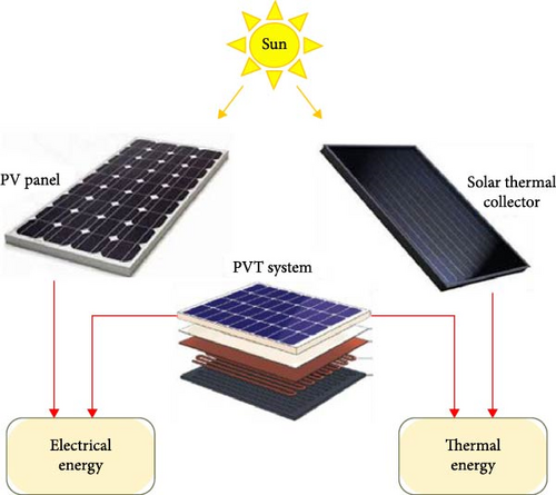
Energy demand is continuously rising owing to the increasing global population [1]. Petroleum, natural gas, and carbon are the main sources for meeting this demand for heat and power generation; however, their massive use raises serious concerns: on the one hand, these resources are finite, and their availability is gradually decreasing; on the other, their exploitation and combustion generate significant greenhouse gas emissions, contributing to global warming, air pollution and ecosystem degradation [2]. Consequently, researchers increasingly turn to alternative energy sources, such as solar, biomass, wind, etc. [3–5]. Solar power’s excellent compatibility with sustainable development and its capacity to continually provide clean power are significant factors in its rising popularity [6]. Solar systems can generate thermal and electrical energy (Figure 1) [7]. Solar thermal systems capture the radiation and convert it into thermal energy using a working fluid, such as air, water, or a mixture of both. Solar photovoltaic (PV) modules remain the primary source of growth in renewable capacity worldwide in 2023, contributing 65% of this expansion [8]. The forecast shows the solar PV industry is growing and will reach 310 GW in 2024, representing a 7% increase compared to 2023 [8]. PV panel transforms sunlight into electrical power. However, as mentioned earlier, the procedure only converts a portion of the sunlight into electrical power. The remaining energy is dissipated as heat, which increases PV panel temperature beyond standard conditions, solar thermal collectors (STCs) (solar irradiance: 1000 W/m2 and cell temperature: 25°C) [9], significantly reducing its efficiency and longevity (Figure 2) [10–13]. This rise in PV panel temperature inherently leads to a contraction of the semiconductor bandgap. This has several consequences: on the one hand, it increases the cell’s ability to take up incident light, which promotes the production of moving charge carriers and increases the short-circuit current (Isc). On the other hand, it reduces the open-circuit voltage (Voc) [14]. It’s important to note that this voltage reduction has a more significant effect on cells with smaller bandgaps, such as silicon (Si) and germanium (Ge), compared to those with larger bandgaps. As the operating temperature rises, crystalline and amorphous Si solar cells successively see their electrical efficiency (EE) decrease by around 0.4%–0.5% K−1 and 0.2% K−1. However, CIS, cadmium telluride (CdTe), and gallium arsenide (GaAs)-based cells decreased their efficiencies by 0.36% K−1, 0.25% K−1, and 0.24% K−1, respectively [14]. As a result, PV thermal (PVT) solar systems have been proposed to improve energy efficiency. PVT systems offer an outstanding solution for heat and electricity generation [15]. This hybridization has increased or even increased PV panel efficiency since cooling its panel and utilizing the dissipated heat to generate thermal power [16]. This technological innovation is of evident interest in various sectors such as housing, industry, agriculture, etc. [17].

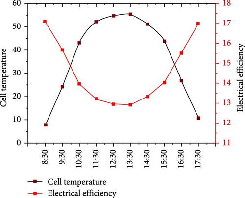
Various methods have been used to ensure the efficient cooling of PV modules. These include water flow control, water spraying, heat pipe operation, water immersion, air-flow management, phase change materials (PCMs), nanofluids, thermoelectric coolants, and transparency cooling [19]. The cooling fluids most commonly used in PVT systems are air and water [20]. However, PVT systems based on the use of air face limitations in terms of heat dissipation efficiency due to their relatively modest thermodynamic properties, notably their low density, limited heat capacity, and reduced thermal conductivity. To overcome these limitations, PVT systems have been developed using water as a coolant to take advantage of water’s superior thermal properties [21, 22].
The history of PVT systems began in the 1970s [23] with the work of Kern and Russel [24]. In recent years, significant advances have been made in developing and improving the efficiency of PVT systems [17]. During this period, the PVT hybrid plate solar system was one of the most popular PVT systems [25]. This system is divided into three distinct parts. First, it comprises solar cells, which can be made from several materials, including monocrystalline Si (m-Si), amorphous Si (a-Si), and polycrystalline Si (p-Si), as well as copper indium gallium selenide (CIGS) and CdTe solar cells [26–29]. Second, it is equipped with encapsulation materials such as ethylene-vinyl acetate (EVA) copolymer, polydimethylsiloxane (PDMS), polyethylene terephthalate (PET), and polyvinyl butyral (PVB) [30]. Finally, it includes thermal absorbers or receiver tubes made from aluminum, copper, copper–aluminum, stainless steel, galvanized steel, polymer, etc. [10].
The structure or geometric configuration of the absorber and the tubes through which the fluid circulates, the choice of heat transfer fluid, the material used to make the absorber and the heat transfer fluid circulation channels, the method of integration, and the type of PV panel used in PVT hybrid systems play a crucial role that can have a decisive impact on their energy conversion efficiency.
- •
A summary of the many studies conducted on the different layers of a flat-plate PVT system, providing an overview of advances in this field.
- •
A summary of the different materials used for absorbers and tubes and the research on each type of material provide a better understanding of their properties and applications.
- •
A detailed examination of possible heat exchanger configurations through a wide range of studies highlights innovative approaches and significant developments in this field of research.
- •
Presentation of the various PVT system simulation software tools, accompanied by a summary of the research undertaken for each software tool, to guide authors toward the appropriate tools for their modeling and simulation needs.
To the author’s knowledge, this is the first document to deal comprehensively with all aspects of flat-plate PV systems and to guide researchers and engineers in this field.
2. PVT Hybrid Solar Systems
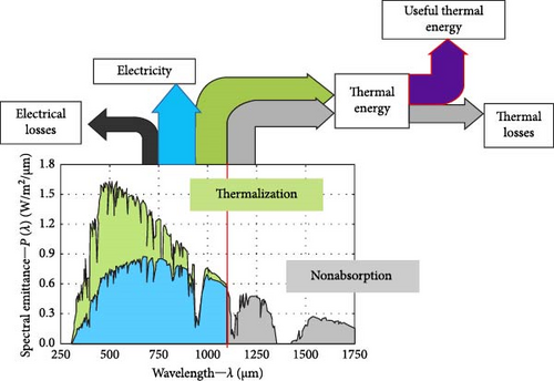
PVT hybrid solar systems, also known as solar cogeneration systems, are advanced technologies that convert solar radiation into electricity and useful heat simultaneously (Figure 3). These systems offer a reliable solution for ensuring energy security while helping to reduce greenhouse gas emissions [11]. To optimize energy production, these systems use a combination of PV cells and STC [31]. PV cells generate electricity from light radiation, while STC captures the heat not used by the cells and helps to dissipate it. In Figure 4, the diagram clearly shows the energy flow inside a commonly used PVT system [32, 33]. This representation highlights the energy losses that result from the thermalization of photons (shown in green) when their energy exceeds the semiconductor’s bandgap (red line) and from the nonabsorption of photons with insufficient energy (shown in gray). In addition, it is important to consider electrical losses that cannot be recovered to maximize the energy efficiency of this type of system. PVT systems offer the significant advantage of keeping PV cells at a low operating temperature by utilizing traditional heat transfer fluids such as water or air [14]. By ensuring constant cooling of the cells, this technique limits losses in EE due to overheating. In addition, the heat extracted from the cells is not lost: it can be recovered to meet thermal needs, such as heating domestic hot water or preheating air in buildings [34]. Thanks to this dual exploitation of solar energy, PVT systems can generate electricity and heat simultaneously, surpassing the performance of PV or thermal systems used separately. This synergy between electrical and thermal production gives PVT systems superior energy efficiency compared with conventional solar solutions operating independently [35].
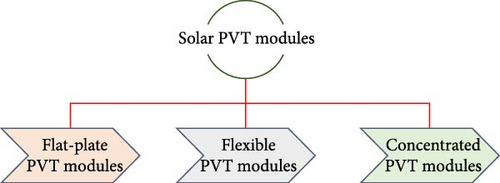
The classification of PVT technologies can be based on the type of PV module they incorporate. Three main configurations can be distinguished (Figure 5) [36]. The first category comprises flat-plate systems, which use conventional rigid PV modules combined with a heat exchanger located at the rear to capture heat. The second category comprises flexible modules, which are characterized by their light weight and ability to adapt to curved or unconventional surfaces, making them particularly suitable for mobile or architectural applications. Finally, the third category comprises concentrating modules, which use optical devices (such as lenses or mirrors) to focus solar radiation onto a reduced surface area of the PV module, thereby increasing efficiency but requiring a more efficient cooling system due to the high temperatures generated. Figure 6 depicts a categorization of PVT systems according to various heat transfer mechanisms, such as air, water, and air–water, and their integration into several conceivable infrastructures. This classification enhances understanding of the characteristics of each system and enables their use to be adapted to specific needs. In addition, PVT systems can be classed based on various system factors, such as absorption plate design, and fluid flow systems, such as forced circulation, number of channels, single-pass, natural circulation, and double-pass [37].
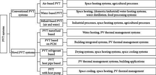
A market analysis was carried out as part of Task 60 of the International Energy Agency (IEA) to evaluate the growth of the PVT systems market and the number of PVT system manufacturers. A total of 26 collector manufacturers and suppliers from 11 countries were surveyed. The results show that most manufacturers focus on liquid-based PVT systems, representing 48% of uncovered PVT systems, 28% of covered PVT systems, and 4% of vacuum tube PVT systems. In addition, 12% of manufacturers produce air-based PVT systems and 8% Concentrated PVT systems [38].
PVT hybrid systems have various benefits and drawbacks that need to be carefully considered, as shown in Table 1.
| Advantages | Disadvantages |
|---|---|
|
|
3. PVT Flat-Plate Systems
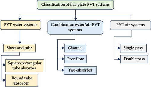
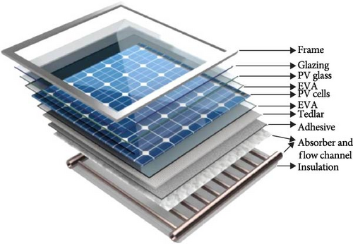
Flat-plate PVT systems are an increasingly popular technology for generating heat and electricity from solar energy. They are composed of a PV panel and a thermal absorber attached to their back surface. The absorber is designed to collect the energy dissipated by the PV panel in the form of heat, thus increasing the overall efficiency (OE) of the system [30]. Figure 7 shows a standard classification of flat-plate PVT systems according to the used refrigerants. These systems’ EE, thermal efficiency (TE), and OE vary according to the selected cooling fluids, ranging from 6.7% to 15%, 22% to 79%, and 40% to 87%, respectively [36]. These systems are frequently used for building heating, air conditioning, industrial heat production, and solar water heating [44]. Due to their simple design and easy maintenance, flat-plate PVT systems offer an economical and reliable solution to thermal energy needs. These systems are designed to enable efficient thermal contact between air or water and the PV module. When air is used as a coolant, it comes into direct contact with the PV panel, while using liquids requires using a heat exchanger to facilitate thermal exchange [14]. These systems are designed to be permanently fixed to an integral part of a building, such as walls or roofs. To ensure the maximum efficiency of these collectors, an appropriate orientation must be chosen for the specific location [6, 39]. The complete design of a PVT flat plate system comprises several components, including a glass cover (tempered glass), a solar cell, an absorber exchanger, and encapsulated materials. Figure 8 clearly illustrates the location of these various components [6, 26].
3.1. Components of Flat-Plate PVT Systems
3.1.1. Glazing
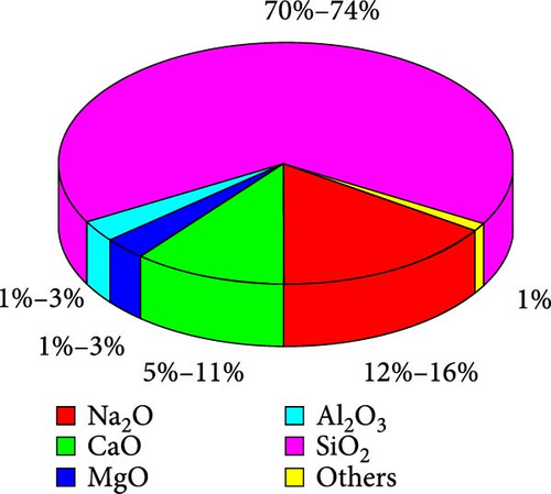
The PVT system is equipped with a first layer of tempered glass, which is essential for the PV module’s sustainability and reliability. This layer of tempered glass, also known as toughened or safety glass, is designed to protect the module from external elements such as water, steam, dust, and dirt [46]. Due to its resistance to external factors, tempered glass is four times stronger than ordinary glass. This glass layer is manufactured from Si oxide (SO2) (Figure 9). Raw materials are heated to extremely high temperatures of over 1560°C to create glass, which is then transformed into tempered glass by heating it to 620°C and rapidly cooling it by air circulation [47].
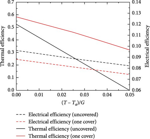
Incorporating additional glazing into the PVT system improves heat absorption and reduces heat loss due to convection, thus improving the collector’s TE [29, 48]. However, this modification also increased PV cell temperature and reflection losses, reducing EE [49, 50]. An interesting study (Figure 10) showed that a covered PVT system has almost twice the TE of an uncovered collector but with a reduction of around 10% in EE [51]. Riffat and Cuce [52] have carried out a comprehensive study of PV and PVT solar systems. This study indicates that using glazing in PVT system installations is not essential. They found that incorporating glazing into PVT systems optimizes thermal and overall energy production. In addition, using unglazed PVT systems offers an advantage over glazed systems in terms of EE since they avoid radiation scattering. Guarracino et al. [29] have conducted a study to assess the effect of glazing on PVT system performance. The results showed that the glazed system recorded 20% lower EE than the unglazed system. In addition, using a glazed cover positively affected the system’s TE. Aste et al. [53] have performed a study to investigate the influence of cover on the performance of a flat PVT system. They used the same system to compare the results with and without a cover. The results of this study indicated that the EEs of the covered and uncovered systems were 6% and 14%, respectively. In addition, covered systems had a higher TE (29%) than uncovered collectors (22%). Pei et al. [54] have shown that glass covering has a positive effect on TE on the one hand and a negative effect on PV efficiency on the other. However, a glass cover improved the system’s global energy efficiency. If the PV panel is to be cooled from above, several layers of glass can be used in front of the module [25]. In this configuration, the glazing layers act as a conduit for the cooling fluid. Using multiple layers has the advantage of improving TE and effectively cooling the PV cells while keeping solar radiation from directly reaching the PV panel [25]. However, a study by Zondag et al. [55] indicated that exceeding three layers of glass is not recommended for PVT systems. Beyond this limit, solar radiation transmission would be significantly reduced, although TE would be improved. Consequently, the authors have recommended three layers of cover glazing to achieve an optimum balance between TE and solar radiation transmission.
3.1.2. EVA
The most commonly used encapsulant is EVA to manufacture crystalline Si PV panels. This choice is explained by the properties of EVA, which have been exploited since 1981 and have enabled us to achieve a current market share of over 80% [56]. It is a thermoplastic material with great commercial importance, produced from ethylene monomer and vinyl acetate, as shown in Figure 11 [57]. The quantity of VA and its variation in the formulation of the EVA encapsulant considerably affect essential properties such as optical transmission, thermal stability, melting point, adhesion force, volume resistivity, and mechanical strength. They are key factors in the reliability of PV modules [58]. EVA has several advantages as an encapsulation material for PV cells [51], particularly its adhesive properties, melt flow, low processing temperature, high elasticity, and high light transmission. Moreover, its low cost makes it a desirable option. However, EVA also has its drawbacks [56], such as low resistance to moisture, heat, and ultraviolet (UV) rays, which lead to rapid degradation and yellowing, resulting in reduced energy conversion efficiency of solar cells.


3.1.3. Tedlar
The back sheet of a solar panel plays an essential role in protecting it against harsh environmental conditions. It presents several important characteristics, such as exceptional adhesion to the EVA encapsulant, satisfactory hydrolytic stability, outstanding weather resistance, durability, and high dielectric strength. It offers adequate protection against physical abrasion, chemicals, and humidity. It also insulates cells and electrical connections from the environment, heat, and UV rays. Its high internal reflection also contributes to improved EE [59, 60]. However, it is essential to note that a conventional back sheet, commonly known as TEDLAR (polyvinyl fluoride), is manufactured from petroleum, which raises significant environmental concerns once it reaches its end-of-life [61]. It is estimated that around 78 million tons of solar panel waste could end up in landfill sites by 2050. In addition, the decomposition process of TEDLAR can lead to chemical reactions that can produce harmful gases [61, 62].
3.1.4. Solar Cells
Currently, various PV cell technologies, based on a wide range of materials, are available on the market, and this variety is expected to expand with technological advancements. They are usually grouped into four generations, depending on the type of material used and their level of commercialization [63]. First-generation PV modules are based on crystalline Si, with wafers produced using techniques already used in the integrated circuit industry. This approach benefits from the expertise acquired in producing Si wafers, giving this generation a remarkable performance [64]. Second-generation PV technologies have been developed to improve the characteristics of first-generation technologies while reducing their costs [64]. This generation includes thin-film technologies such as CdTe, a-Si, CIGS, and GaAs single-junction cells [65]. The third generation consists of innovative PV technologies such as multijunction solar cells, organic PV (OPV) solar cells, concentrating PV (CPV) systems, and dye-sensitized solar cells (DSSCs). Hybrid solar cells of the fourth generation represent an advanced stage in the development of inorganic compound PV technologies. These cells are designed to achieve significantly greater energy transformation efficiencies than third-generation cells, thanks to the use of more efficient materials and new optimization techniques. However, this improved performance comes with a higher initial cost, mainly due to the advanced materials and complex manufacturing processes involved.
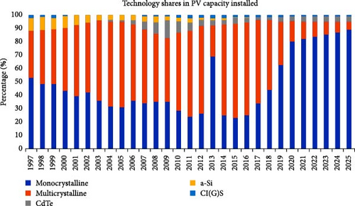
According to a study by the Fraunhofer Institute [66] and estimates by the International Renewable Energy Agency [67], the percentage of second-generation technologies should be around 5% between 2022 and 2025. In addition, amorphous modules (a-Si) are unlikely to be used in practice [68]. Regarding first-generation technology, m-Si modules are expected to outnumber p-Si modules. This tendency is due to the improvement of monocrystalline technology, which has become a viable competition in price while offering superior efficiency [68]. Figure 12 shows a distribution of the market for different solar technologies.
The significant variation in the performance and OE of PV panels is attributable to using different semiconductor materials in each generation [69]. A solar cell material must have a bandgap between 1.12 and 1.7 eV to be considered ideal. Indeed, a smaller bandgap facilitates the transfer of electrons from one band to another, thus increasing the material’s conductivity. In addition, an ideal material must be abundantly available, nontoxic, and easy to manufacture [63]. Extensive investigations have been conducted over many years to increase the performance of PV solar energy systems and achieve optimum efficiency. Recent research results on PVT systems, classified according to the type of PV cell used, are presented in Table 2.
| Year/reference | PV cell | Thermal efficiency (%) | Electrical efficiency (%) | Total efficiency (%) | Type of study |
|---|---|---|---|---|---|
| 2009 [70] | p-Si | 45.0 | 10.0 | 55.0 | Exp |
| 2011 [71] | m-Si | 56.0 | 11.0 | 67.0 | Exp |
| 2012 [72] | InGaP/InGaAs/Ge | 56.0–63.0 | 20.0–23 | 77.0–83 | Theo |
| 2013 [73] | Triple junction | 27.0–58 | 18−24.0 | 45–82.0 | Theo |
| 2014 [74] | Triple junction | 41.60 | 23.10 | 64.70 | Theo + Exp |
| 2015 [75] | Triple junction | 34.10–38.70 | 20.0–25.0 | — | Theo |
| 2016 [76] | Si | 50.0 | 38.0 | — | Theo + Exp |
| 2017 [77] | GaAs | 52.58–56.37 | 7.12–7.94 | 61.0–63.5 | Theo |
| 2018 [78] | m-Si | 24.0–36.0 | 20.0–24.0 | 30.0–47.0 | Exp |
| 2019 [79] | p-Si | 56.70 | 11.80 | 66.40 | Theo |
| 2019 [80] | m-Si | 79 | 8.7 | 88.0 | Theo |
| 2021 [81] | m-Si | 82.55 | 10.45 | — | Exp |
| 2022 [82] | m-Si | 53.50 | 20.80 | — | Theo + Exp |
| 2023 [83] | m-Si | 15.0–52 | 15.0–19 | — | Exp |
- Abbreviations: Exp, experimental; Theo, theoretical.
3.1.5. Isolation
In the field of PVT systems research, different types of materials have been investigated for insulating the back of the absorber to reduce heat loss while increasing the temperature of the fluid leaving the collector [84]. Available options include rock wool, high-density polyethylene, polyethylene foam, and asbestos [48]. In addition, it is common practice to insulate the rear of the PVT system with fiberglass, which is then covered with an aluminum shell to minimize heat loss from the heat absorber [85]. These different insulation methods play an essential role in optimizing the performance of PVT systems, maximizing energy efficiency, and maintaining higher temperatures for the fluid.
3.1.6. Thermal Absorbers for PVT Systems
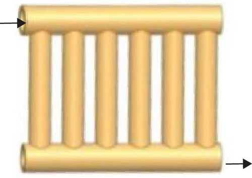
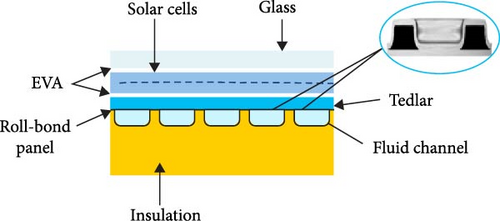
The heat absorber plays a crucial role in a PVT system, evacuating its heat as a working fluid flows through these integrated channels. These channels, located at the back of the absorber, act as heat exchangers. Heat dissipation keeps PV cells cool, improving their EE. Heat transfer between PV cells, fluid, flow channels, and absorbers depends on various factors, such as the integration method of all these elements, structural design, material conductivity, and thermal resistance [86]. The different types of flat absorbers used in PVT systems include sheet and tube, box channel, flat tube, and roll-bond [31, 87]. Sheet and tube PVT collectors mainly consist of a plate and a tube, commonly made of aluminum, steel, or copper due to their excellent thermal conductivity. The tube can adopt a variety of configurations, notably in the form of a coiled tube with one or more paths, such as a heat pipe or parallel tube (Figure 13) [36, 87]. PVT sheet and tube collectors are an effective solution for meeting the hot water needs of residential buildings. Although they may be slightly less performant than channel collectors, they remain an attractive option regarding TE. Moreover, PVT sheet and tube collectors are easy to fabricate and affordable, making them an appealing choice [44]. In the study conducted by Fang et al. [88], the sheet and tube heat absorber were mounted behind the PV module, resulting in a significant decrease in its operating temperature from 52.0 to 8.0°C. This decrease in temperature has a positive effect on the EE of this PV module, with an increase of 23.8%. Ji et al. [89] produced the sheet and tube-type PVT module. Experimental results showed a remarkable EE of 13.7%. However, they observed that welding reduced the heat exchange area between the tube and the PVT system absorber plate. This reduction resulted in higher thermal resistance, limiting the tube’s efficiency in extracting heat [90]. As a result, both TE and EE were lower. To address these problems, adopting a PVT system roll-bond increased the heat exchange surface area, providing an effective solution [90] (Figure 14). According to a comparative study by Del et al. [91], the roll-bond absorber outperforms the sheet-and-tube absorber. Zhou et al. [92] carried out an experimental study to investigate the performance of a PVT system roller bond. The results showed an average EE of 11.8%. The results showed an average EE of 11.8%. Then, Shao et al. [93] realized a concrete application by installing the same type of PVT system on the roof of a building to produce both heat and electricity. The TE and EE obtained are 60.2% and 11.7%, respectively.
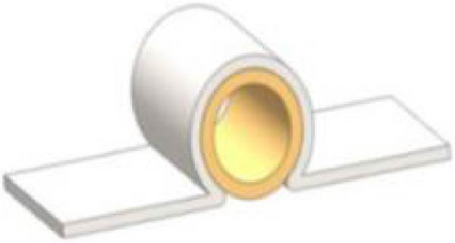



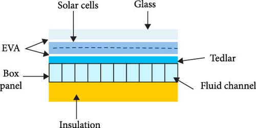
The “box channel” structure comprises parallel ducts of rectangular sections (Figure 15). Usually made of aluminum from an extruded or pultruded profile, this structure can also be made from polymeric materials, such as fiberglass or rubber [84, 95]. However, their high thermal expansion coefficient limits the use of plastics, making it difficult to bond them to the PV panel. In addition, their limited resistance to high temperatures and low thermal conductivity restrict their use in this application [95]. Assembling input and output collectors with the rectangular channel requires specialized components, which entails considerable costs and technical problems [84, 96].
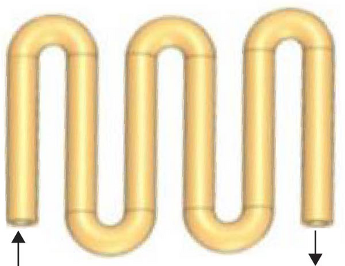
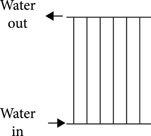
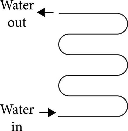
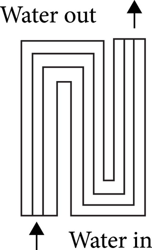
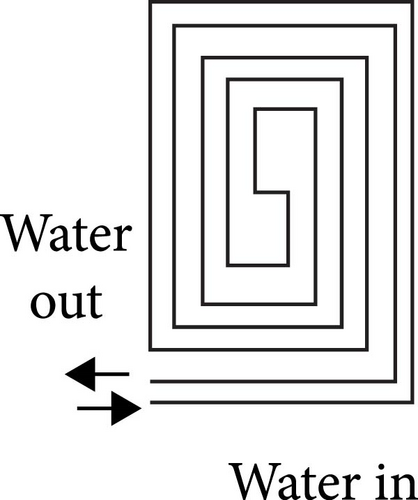
The flat-plate tubular collector presents a specific configuration with circular or rectangular cross-section tubes integrated flat and round into the PV panels. The most commonly used models are the spiral and the serpentine (Figure 16) [87, 97]. These collectors have at least one input and output to circulate the working fluid. These thermal absorbers are designed to improve contact between the absorber and the PV layer. However, this tubular collector has problems, such as increased fluid temperature in the flow direction, high resistance, and potential risks of leakage and obstruction. In addition, most flat tubular absorbers are used exclusively in water-cooled flat PVT systems, limiting their applications [36, 97].

3.1.7. Methods of Integrating Heat Absorbers Into PVT Systems
To realize PVT systems, the primary step is to attach a commercially available PV solar panel to a thermal collector [25]. The choice of collector plate and the fixing criteria are of great importance to ensure the optimum TE of the collector [52]. This can be achieved using mechanical or chemical integration methods [36]. If the thermal contact between the heat absorber and the PV panel is deficient, this leads to inefficient heat transfer [98] and a temperature difference of around 15.0°C for an unglazed system [84]. This results in a reduction in EE and, in the longer term, in thermal deterioration of the PV cells [98]. Previous research has found that improving this thermal contact makes it possible to reduce the temperature of PV cells by 10°C, resulting in an increase in EE of 6%–8% [29]. Furthermore, it should be noted that the presence of tiny air bubbles in the integration layer can lead to considerable thermal resistance between the heat absorber and the PV panel [36]. Consequently, the choice of the integration method and absorber used is essential in PVT systems, as it directly impacts the PV panel cooling process and their EE, TE, and OE [31, 36]. The thermal absorber’s integration layer must have specific essential characteristics to ensure efficient cooling and optimum TE, EE, and OE. First, it must have a high thermal conductivity [31] and adequate thermal capacity. In addition, it must be able to operate over a wide temperature range to compensate for temperature variations between the thermal absorber and the PV layer. It is also essential that the integration layer can expand without degradation to resist temperature differences between the various components. Finally, it must be dielectric to avoid electrical short-circuit problems. Table 3 summarizes the different methods of integrating PV modules with thermal absorbers and outlines each method’s advantages and disadvantages.
| Method | Description | Advantages | Disadvantages |
|---|---|---|---|
| Thermal adhesive | Use an adhesive layer of epoxy, silicon, or elastomers in film or mucilage form to mechanically integrate the PV panel with a thermal absorber. These materials have a thermal conductivity of between 0.8 and 11.4 W/m K |
|
|
| Mechanical fixing | Mechanical fastening is used to firmly attach the heat absorber to the PV panel. This method is commonly used in flat-plate and concentrating PVT collectors. It can involve the use of screws, springs, straps, brackets, clips, etc. |
|
|
| Direct contact integration | Combining thermal absorbers and PV layers by direct contact without adhesives or mechanical fasteners. This method significantly improves TE, with an increase of over 50% |
|
|
| EVA–based lamination | EVA lamination is used to integrate PV modules and heat absorbers. Compared to traditional approaches, this technology reduces the dangers associated with uneven adhesive thickness and the production of tiny air gaps or bubbles between the PV panel and the absorber plate |
|
|
3.1.8. Absorber Materials
The optimum choice of PVT systems material is based on its ability to transfer heat efficiently [48]. High heat transfer coefficients are crucial to improving the thermal management of PVT systems. Thus, it is essential to find an appropriate compromise between the heat transfer characteristics of the absorbent material and those of the fluid used. When the absorber material used in a PVT system has a low thermal conductivity, it becomes necessary to compensate for this limitation by opting for a heat transfer fluid with a higher thermal conductivity to ensure efficient heat extraction and improve overall system efficiency [99]. On the other hand, if the thermal channel is made of a highly conductive material, the use of conventional fluids remains sufficient, as heat dissipation is naturally facilitated. What’s more, in some applications, the properties of standard fluids can be adjusted to suit the characteristics of the absorbing material and the specific thermal requirements of the system [99]. Absorber plates can be avoided to reduce the cost and weight of PVT systems [100]. Traditionally, these plates were mainly made of copper, which is recognized as one of the best thermal conductors. However, these collectors became too expensive with the rise in copper prices. As a result, designers set out to find more affordable alternatives that would still deliver satisfactory efficiency [101]. Many researchers have widely adopted the choice of copper as an absorbent material for designing PVT systems [102]. Nardi et al. [103] tested a commercial PVT system using a copper absorber and water as the heat transfer fluid. In an experimental evaluation carried out over several summer days, they measured the system’s electrical performance. The results showed that this PVT system offered 14%–18% higher EE than a standard PV panel. Kalogirou and Tripanagnostopoulos [50] have realized TRNSYS simulations analyzing two types of PVT systems (two polycrystalline and amorphous PV panels) using copper absorber tubes. Their investigations showed a significant improvement in TE for the amorphous Si module and a 38% increase in annual electrical energy production for the polycrystalline Si module. However, they pointed out that more significant economic benefits would be seen in regions benefiting from more intense solar irradiation. Aluminum is the second-best conductor widely available for plates, just after copper. Although its thermal conductivity is not as high as that of copper (Figure 17), it remains satisfactory [101]. Mojumder et al. [104] have experimentally studied PVT systems using aluminum fins and air as the heat transfer fluid. These experiments explored various mass flow rates (FRs) and solar irradiance (G), ranging from 0.020 to 0.140 kg/s and 200–700 W/m2. The results showed that for the maximum mass, FR of 0.14 kg/s, TE and EE reached 56.19% and 13.75%, respectively. Under various tropical conditions, Dubey et al. [105] conducted experiments on a PVT system using two thermal absorbers: copper and aluminum. Their study showed that the average EE and TE obtained were 11.8% and 40.7%, respectively, for the copper absorber, while those for the aluminum absorber were 11.5% and 39.4%. The use of aluminum is limited by its main drawback: insufficient resistance to corrosion in acidic environments. However, it does have its advantages: its lightweight, high thermal conductivity, and ductility make it a more adaptable material for manufacturing [99]. Copper tubes are widely preferred due to their availability in different shapes and sizes and easy curability. These advantages make copper the most commonly used tube material. Herrando et al. [106] conducted extensive research and concluded that there was no significant difference in thermal performance between copper and aluminum tubes. Similar results were obtained by Nahar et al. [100]. As a result, they suggested that aluminum should be chosen as it is less expensive and lighter. Other researchers have also investigated using steel tubes as absorbers as part of their research on PVT collectors. Kazem et al. [107] studied the performance of a PVT system using a rectangular stainless steel absorber with a direct flow configuration as a collector. Water was used as the working fluid for this system and tested under various climatic conditions in Oman. The results showed that at a mass FR of 0.02 kg/s, the average power produced by the PVT system was 6% higher than that of a standard PV panel. Paradis et al. [108] have conducted a numerical simulation of a PVT solar evaporator, adopting a panel equipped with 60 monocrystalline cells. Their study focused on using a steel absorber and two-phase carbon dioxide (CO2) as the working fluid. The absorber tubes were arranged in serpentine form for this configuration and attached to a stainless-steel sheet. Using a diphasic flow model, results showed an improvement in EE of up to 16.0%. In addition, TE reached an impressive rate of 72.3%. On the other hand, stainless steel has major drawbacks, such as its weight and propensity to corrosion in environments with a pH above 7. These characteristics considerably limit its use in PVT applications, especially on a large scale [99]. Although steel benefits from good thermal conductivity and a high convective heat transfer coefficient, it is often considered unsuitable due to its incompatibility with various fluids and manufacturing constraints [99]. Polymers are preferred as collection materials in modern PVT systems due to their lightness and affordability [98, 106]. The use of polymer materials reduces the weight of the collector by 50% compared to a standard metal collector, greatly simplifying the installation process [109]. Several authors [10, 110] have concluded that certain polymer materials, such as polycarbonate (PC), are attractive for PVT systems. These materials have several advantageous properties, such as low density, no need for specific surface treatment, corrosion resistance, mechanical resistance, ease of series production due to fewer components to assemble, and reduced production costs thanks to economical material availability and reduced manufacturing time. Polymeric materials, while offering certain advantages, also have several notable disadvantages. One of the main disadvantages is their low thermal conductivity compared with metals such as copper and aluminum [10, 110]. This difference can create problems at the interface between PV panels and heat absorbers, affecting overall system efficiency [99]. Moreover, polymers have a relatively high factor of thermal expansion, which means that they expand or contract more with temperature variations, causing mechanical stress on neighboring materials. Finally, these materials have limited resistance to the high temperatures typically encountered in PVT systems, which can reduce their durability and long-term performance [10, 110]. Because of these constraints, polymer materials are not recommended for designing and manufacturing heat absorbers in PVT systems [84].

Metal matrix composites (MMCs) are a recently developed material offering great promise as an absorbent material. They consist of a reinforcement and a metal matrix and present exceptional thermomechanical properties [99, 110]. MMCs are characterized by their ability to resist high operating temperatures, high thermal conductivity, and high specific resistance. Despite these advantages, scientists have not yet explored their use in PVT systems [99].
3.1.9. Absorber Configurations
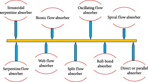
Absorber architecture is paramount in PVT systems, as it determines the ability to extract the heat generated by PV cells efficiently. By ensuring good heat dissipation, it keeps the module temperature at a moderate level, which contributes directly to improving its energy efficiency. Good design enables higher working fluid temperatures to be maintained. Various absorber designs were analyzed to improve heat exchange between the rear surface of the PV panel and the heat collection system (Figure 18). Absorber design depends on panel size, working fluid, thermal energy removal, absorber position, and operating conditions [99].
This section reviews several works on thermal absorbers, highlighting the configurations analyzed as well as their influence on the overall performance of PVT systems.
Ibrahim et al. [111] studied the performance of various PVT system configurations, as shown in Figure 19. They observed that the PVT system with a spiral absorber displays the highest TE and EE, reaching 50.12% and 11.98%, respectively. However, the PVT system with serpentine flow had the lowest efficiency. The study shows that closely spaced absorbers, such as serpentine and oscillating flow absorbers, offer better performance. The EE of PVT systems remains similar regardless of the heat absorber model used. The PVT system with a spiral flow absorber has an EE of 11.98%, while that with a serpentine flow absorber reaches 11.89%.
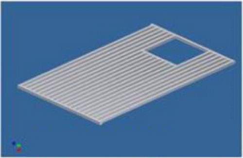

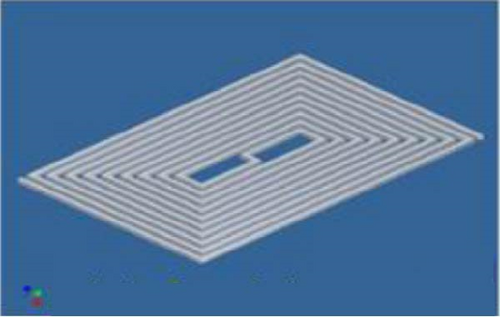

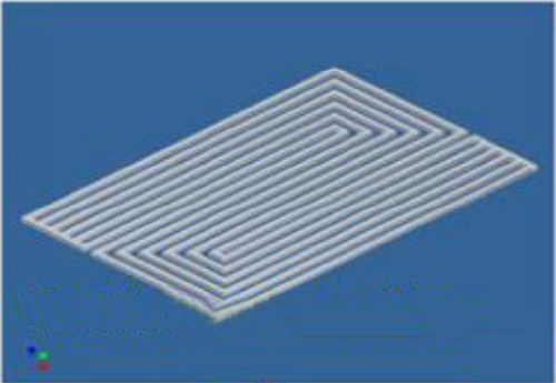
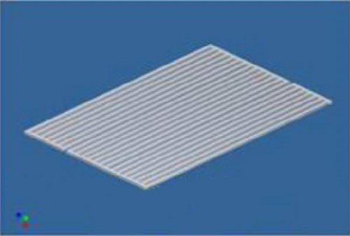
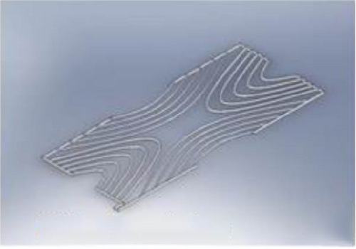
Fudholi et al. [112] evaluated the performance of water-circulating PVT absorbers with three flow configurations (sheet, direct, and spiral) (Figure 19a,c,g) under solar irradiation from 500 to 800 W/m2 and mass FRs from 39.6 to 147.6 L/h. The spiral-flow absorber showed the best results, with a maximum PVT efficiency of 68.4%, a PV efficiency of 13.8%, a TE of 54.6%, and a primary energy-saving efficiency of up to 91%.
Kazem et al. [107] undertook a numerical and experimental study to examine, evaluate, and compare the thermal and electrical performance of three distinct PVT flow configurations compared with standard PV modules. The different flow configurations tested included spiral, sheet, and direct flow (Figure 20). The results of the study show that electrical performance is highest for the spiral-flow system, followed by the sheet-flow and direct-flow systems. Similarly, overall and TEs follow the same trend among the systems analyzed. Conventional PV modules—sheet, direct-flow, and spiral—have average daily EEs of around 7.87%, 8.71%, 8.71%, and 9.11%, respectively. Meanwhile, the average TEs are around 9.8%, 19.3%, and 26.0%. Regarding overall average daily efficiency, PVT systems in sheet, direct, and spiral flow configurations reach around 18.5%, 28.0%, and 35.0%, respectively.
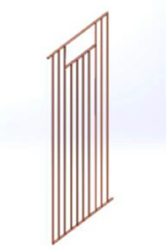
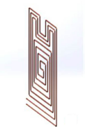
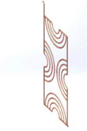
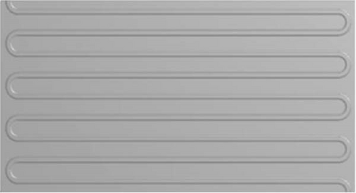
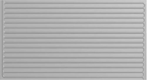
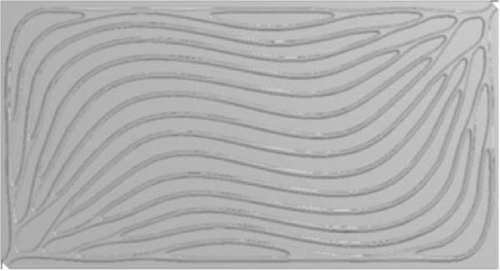
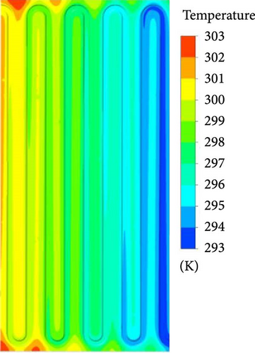
Poredoš et al. [113] conducted a numerical and experimental evaluation to measure the energy efficiency of different water-based PVT system configurations with absorber plates combined with rollers. They studied three types of channels: bionic, series, and parallel (Figure 21). According to the simulation results, the bionic heat exchanger maintained the lowest water output temperature, averaging 44.1°C (Figure 22c), compared with 46.5°C for the series absorber (Figure 22a). In terms of pressure drops, the bionic absorber presented much lower values than the parallel configuration, with an average of 778 Pa, and also proved to be the most energy-efficient.
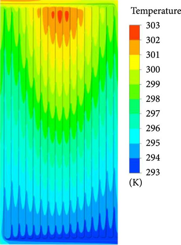

Sheshpoli et al. [114] have carried out numerical and experimental studies to evaluate various cooling configurations for PVT systems. They simulated various configurations (Figures 23 and 24) to determine the best performer and found that serpentine tubes significantly improved EE (7.3%) and TE (48.4%) compared to no cooling. At maximum performance, OE reached 51.76%.
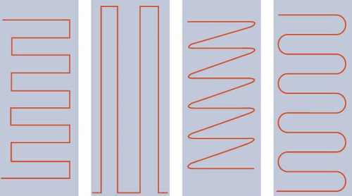
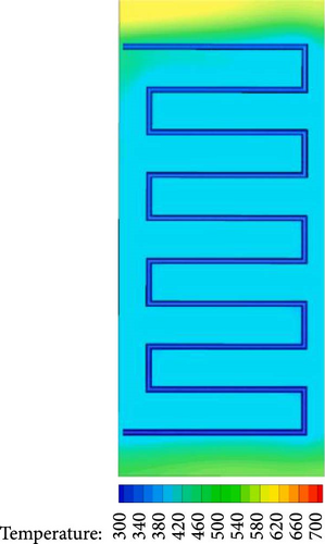
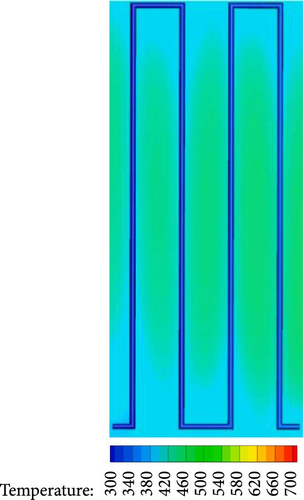
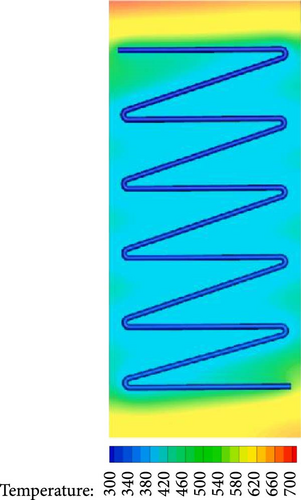
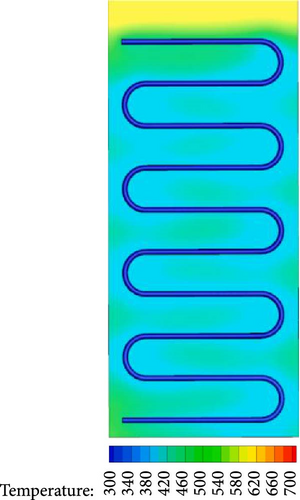
Ibrahim et al. [70] designed and built two PVT systems: one with a rectangular once-through tunnel absorber and the other with a spiral flow (Figure 25). Their study showed that the spiral flow system performed better, offering higher EE and TE.
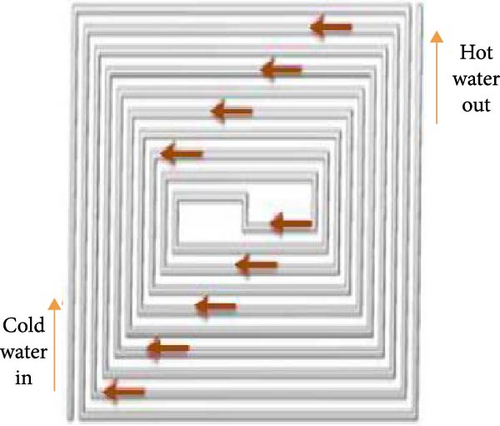
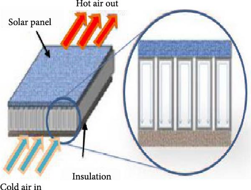
Nasrin et al. [115] have suggested an innovative PVT system design incorporating a nanofluid to optimize system efficiency (Figure 26). A centrifugal pump was utilized to cool the PVT system. This study enhanced the EE and TE by 9.2% and 36.0%, respectively.
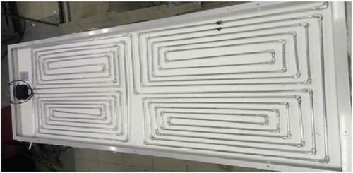
Hossain et al. [116] proposed a PVT system using a Roll Bond collector (Figure 27) with a two-sided serpentine tube tested under the climatic conditions of the Malay Peninsula. The aim of their study was to analyze the performance of a PVT system combined with PCMs. The results showed that this system achieved a TE of 87.72% at a FR of 2 LPM and an energy efficiency of 11.08% at 4 LPM.
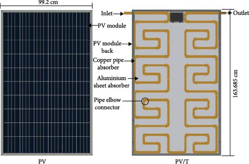
Shahsavar [117] carried out a comparative investigation between a modified sinusoidal coil and a standard sinusoidal coil (Figure 28). The results show that the increase in EE was modest, reaching only 2.32% compared with the standard collector. In contrast, a considerable improvement in TE was observed, with an increase of 30.63% for the modified collector. These findings underline that although the modified manifold offers significant thermal gains, its impact on energy efficiency remains relatively limited.
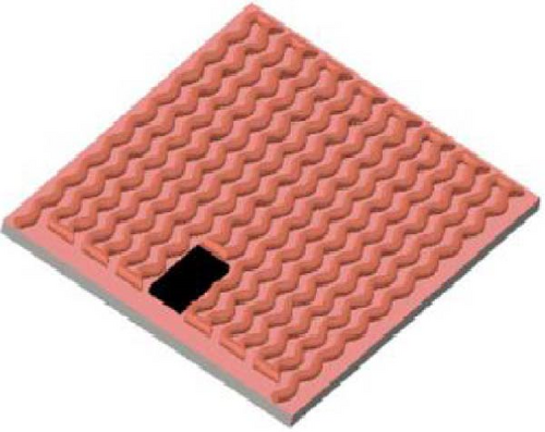
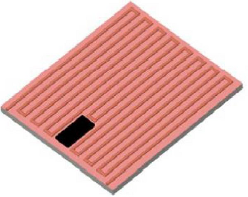
Another comparative study of three water PVT systems in terms of thermal performance was carried out by Sopian et al. [118]. The collectors studied included parallel, fractional, and direct flow models (Figure 29). The results showed that the split-flow collector provided higher thermal performance than the other configurations.
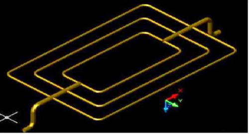
Next, Alshibil et al. [119] developed a new absorber configuration by integrating louvered fins into the tubular absorber to enhance the performance of hybrid solar systems. This study analyzed three different systems: a bi-fluid PVT system, an air-based PVT system, and a conventional PV panel (Figure 30). The average EE and TE of the standard PV panel are around 5.9% and 0%, respectively. The air-cooled system, on the other hand, has EE and TE of 6.7% and 34.26%, respectively. Next, the dual-fluid PVT system achieves EE and TE of 7.56% and 66.17%, respectively. In addition, they showed that this new configuration reduced the temperature of the PV panel by 19.2°C compared with the standard configuration.
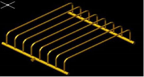
Yu et al. [120] examined channel configuration’s influence on a PVT system’s performance. They compared two types of absorber plates connected by rollers (Figure 31a,b). The results show that the PVT system with a grid channel (PVT-b) outperformed the PVT system with a harp channel in terms of electrical and TE. In addition, the PVT-b was recommended for applications requiring forced circulation.
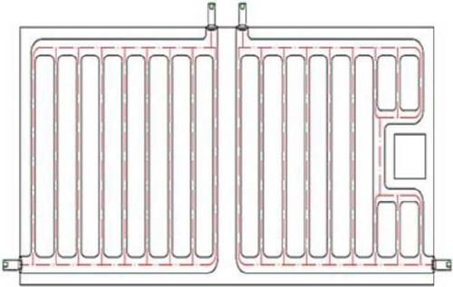
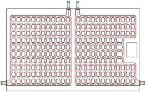
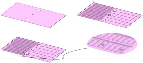
Yildirim et al. [121] presented a new thermal collector for PVT systems. This innovative design was made from an aluminum alloy and comprises three channels for each flow. Each collector section has an input and an output (Figure 32). The three central openings are specifically designed to allow the electrical connection of the PV panel, but they increase the temperature in the area adjacent to these openings. For a mass FR of 0.0140 kg/s and an input temperature of 15°C, the results of this study indicate that the PV panel achieves an EE of 17.79% and a TE of 76.13%.
Abdullah et al. [122] have suggested a new oscillating double-flow copper absorber for a water-cooled PVT system (Figure 33). Combining experimental laboratory tests and MATLAB simulations, they compared the performance of this system with that of an uncooled PV panel. The experimentally validated results showed that the absorber achieves a maximum EE of 11.5%, a TE of 58.64%, and an OE of 66.87% at solar irradiation levels of 500–1000 W/m2 and FRs of between 2 and 6 LPM.
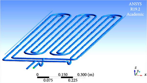
Sachit et al. [123] suggested a new PVT system design incorporating a serpentine-direct flow absorber, which they compared with a conventional serpentine configuration (Figure 34). Using MATLAB-validated simulations, the performance of both designs was evaluated under irradiances ranging from 300 to 1100 W/m2 and for mass FRs between 39.6 and 360 L/h. The results showed that the new configuration achieved a TE of 53% and an EE of 14.3% at 900 W/m2 and 0.06 kg/s. The study also showed that increasing the FR improves cell cooling, reducing cell temperature and increasing EE.

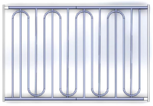
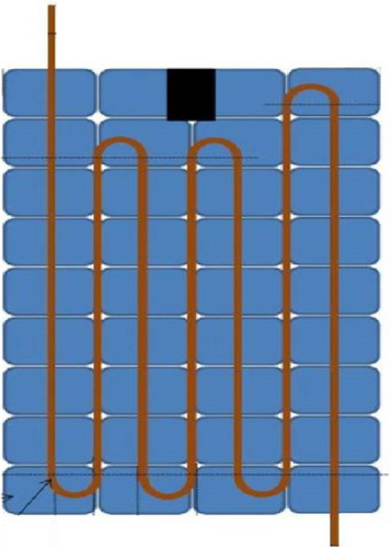
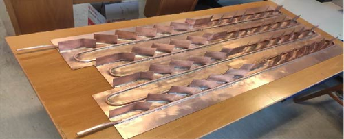
Verma et al. [124] compared a flat plate STC with a spiral configuration to a traditional harp design (Figure 35). At a mass FR of 93.6 L/h, the results showed that the spiral configuration outperformed the harp configuration, with a 21.45% improvement in thermal performance.
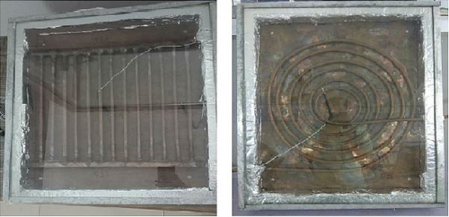
Hossain et al. [125] conducted a study in which they developed an innovative serpentine collector. They then conducted laboratory tests to evaluate PVT systems’ efficiency with this collector (Figure 36). The study concentrated on the effect of water mass FR on system energy efficiency, and the results obtained showed a significant variation in energy efficiency, ranging from 7.16% to 12.98%.
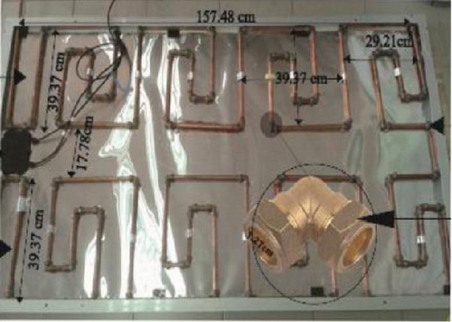
Hocine et al. [126] created a new PVT systems model and tested its electrical and thermal performance. In this study, the absorber was configured using an assembly of two exchangers. The first exchanger comprises parallel vertical tubes, while the second is integrated into an enclosure (Figure 37). They found this design had an EE of 12.7% and a TE of 36.32%.
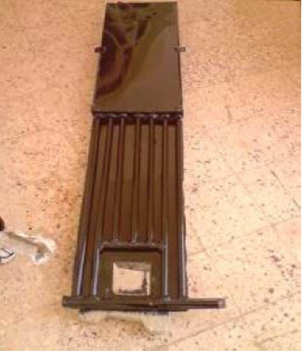
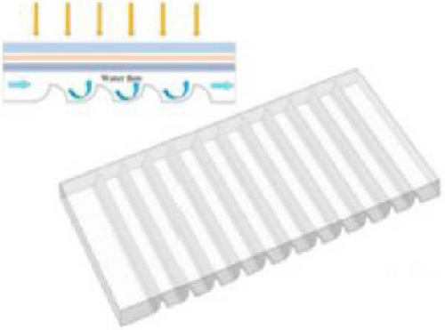
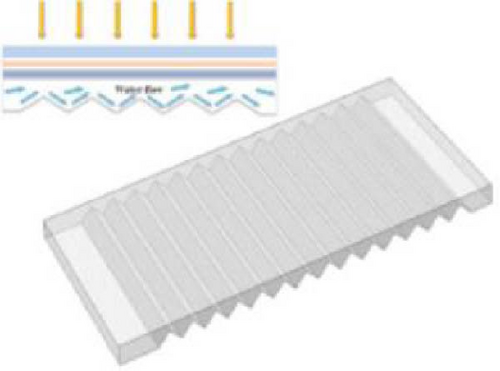
Shen et al. [127] studied a PVT system with an optimized sawtooth cooling channel, which reduced cell temperature by 6.05°C compared with a standard smooth channel. EE increased by 0.5% as irradiance decreased and by 1.11% as cooling water mass FR increased (Figure 38).
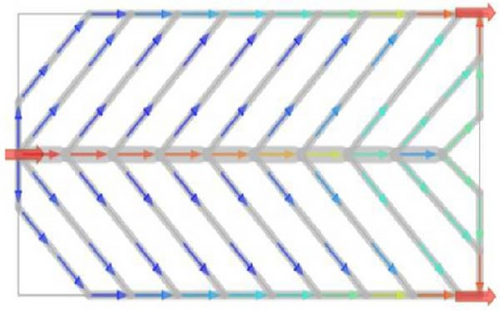
Zhang et al. [128] have studied a symmetrical leaf-like heat exchanger for a PVT system, which offers improved thermal distribution. Compared with a conventional design, it reduces cell temperature by 5.31°C, halves the pressure drop, and improves OE by 4.36% (Figure 39).
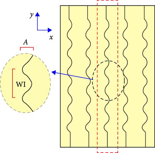
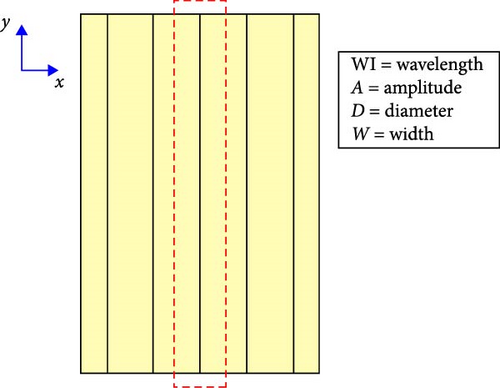
Kazemian et al. [129] studied a PVT system incorporating a wavy collector tube absorber to improve performance. Optimization of wavelength, amplitude, diameter, panel width, and fluid inlet velocity increased overall energy and exergy efficiencies to 85% and 14.67%, compared with 72.41% and 12.72% for a straight-tube system (Figure 40).
Kazemian et al. [130] studied different collector designs and analyzed their impact on system performance. The results show that the PVT system with a multipath serpentine design performs best overall power, achieving an average power of 423.84 W/m2 (Figure 41).

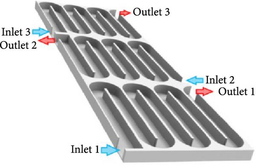
El Alami et al. [131] have investigated a new channel PVT system, optimizing the height of the collectors and the number of channels. Simulations and experimental tests showed that design 8 delivered an OE of 89.42%. The system in aluminum showed a better cost-performance ratio, with a return on investment of 0.823 years and annual cost savings of $459.26, while being 38% more lightweight than the copper system (Figure 42).

Attia et al. [132] investigated the performance enhancement of PVT systems by comparing two cooling configurations using computational fluid dynamic (CFD) analysis. The first configuration uses longitudinal tubes under the panels, while the second incorporates aluminum skeleton tubes under the cells. Air and water cool both systems at a FR of 0.0025 kg/s. The results show that configuration 2 offers better performance: a thermal improvement of 24.3%, an electrical improvement of 0.16% with air, a thermal improvement of 7.27%, and an electrical improvement of 3.98% with water (Figure 43).


Using CFD simulation, Attia et al. [133] analyzed a PVT collector with two cooling channel configurations. The reference system (Figure 44a) uses a zigzag channel, while the modified system (Figure 44b) divides the flow into sections with double-pass tubes (Figure 44). For irradiance levels ranging from 200 to 1000 W/m2 and FRs from 0.001 to 0.005 kg/s, the case of Figure 44b improves TE by 7.23% (water) and 15.75% (air), and EE by 4.0% (water) and 4.6% (air) compared to that of Figure 44A.

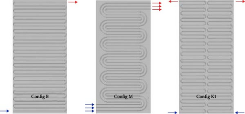
Olmuş et al. [134] used COMSOL Multiphysics to study 25 PVT serpentine system configurations. Configurations K1, M, and B showed the best performance. Higher FRs improved thermal and EE, while higher inlet temperatures reduced them. Pressure drop decreases with the number of inlets (Figure 45).
4. Simulation of PVT Systems
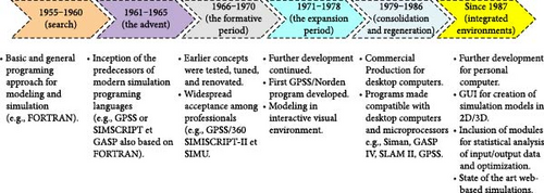
Research can be a challenging endeavor, especially when it comes to solving complex problems. Researchers often need to conduct intensive experiments to achieve their goals. However, many technical and commercial constraints can hinder the implementation of experimental techniques. Physical experiments are usually costly and time-consuming, which can complicate the process. Fortunately, technological advancements have led to increasingly sophisticated modeling and simulation techniques. These simulations are relatively inexpensive and fast, making conducting experiments with iterative parametric configurations easier. Since the 1920s, modeling and simulation have dramatically evolved (Figure 46). The most significant technological advancement was reported in the 1950s when electronics replaced heavy machinery, encouraging simulation development and large-scale industrialization. The 1960s marked a turning point in the history of computing with the introduction of digital computers that significantly advanced modeling and simulation. Finally, computer graphics were introduced to the commercial market in the 1990s, providing a more user-friendly experience and making simulation easier for researchers and professionals across various industries [135, 136].
Research on PVT systems has experienced significant development through the use of software to perform mathematical modeling, whether with or without field experiments. This modeling can provide valuable insights to researchers about possible experimental outcomes. However, it is essential to note that the accuracy of the results depends on the quality of the input data—the more precise the input data, the closer the result to reality. Additionally, the number of factors considered in the modeling also influences the accuracy of the results. However, it is essential to remember that mathematical modeling can yield different results from field tests, mainly due to uncontrollable factors such as variations in wind speed, temperature changes, and solar radiation blocked by dust or other impurities [48, 126].
ANSYS, TRNSYS, and COMSOL Multiphysics are the most commonly used software for simulating PVT systems. There are other types of software available for simulating solar collectors as well. Among these, PolySun, Solo, STAR-CCM+, PVGis, PVSyst, PV F-CHART, T∗SOL, RETScreen, EnergyPlus, SolarPro, and MATLAB/SIMULINK can be mentioned. Each of these software offers different features, with some focusing solely on PVs (e.g., PVSyst, PVGis), others on thermal aspects (e.g., Solo), and some capable of modeling hybrid systems (e.g., PolySun, TRNSYS, MATLAB/SIMULINK, STAR-CCM+, COMSOL Multiphysics, ANSYS). The choice of software depends on the specific needs of each user, such as model complexity, simulation accuracy, required features, and cost. Table 4 summarizes some studies conducted on PVT systems and the types of software used.
| Authors/reference | Year | Description | Software |
|---|---|---|---|
| Fan et al. [137] | 2019 | Based on MATLAB and EnergyPlus software, modeling and optimizing a desiccant cooling system coupled with solar thermal heating of PV air were performed |
|
| Brottier et al. [138] | 2020 | A statistical analysis assessed the on-field performance of 28 hybrid solar installations dedicated to domestic hot water production in Europe (France, Switzerland, and Portugal). In this study, the authors employed five different software tools to quantify the estimation errors of statistical predictions compared to real-world data |
|
| Fu et al. [139] | 2021 | The overall performance of a PVT system with a multilayer structural heat exchanger containing PCMs was examined using MATLAB. Experimental validation was conducted to validate the simulation results | MATLAB |
| Bisengimana et al. [140] | 2023 | Using the TRNSYS software, a simulation was conducted on a system that integrated a PVT collector. This study aimed to examine the PVT system’s efficiency in providing heating and cooling for the building throughout the year under the specific meteorological conditions of Chengdu, Sichuan, China | TRNSYS |
| Ahmadinejad et al. [141] | 2023 | The software ANSYS Fluent 2021-R2 was used to perform numerical modeling and assess an innovative PVT system’s energy and exergy performance using nanofluids and baffles | ANSYS |
| Authors [131, 142–152] | 2018–2024 | Using the COMSOL Multiphysics software, numerical/experimental analysis of the PVT–PCM/PVT/PV systems’ performance for different flow regimes was conducted | COMSOL Multiphysics |
5. Discussions
This article provides an in-depth examination of various aspects of flat-plate hybrid PVT systems based on recent research. This section presents and discusses the main results obtained.
PVT systems have been extensively studied, particularly their design variations, operating fluids, and other factors influencing their performance. The efficiency of a hybrid PVT system relies on a combination of parameters that are crucial to achieving an optimized system. These parameters include geometrical, geographical, meteorological, internal, and external/climatic factors [153]. Design parameters include factors such as PV cell selection, collector dimensions (length and depth), thermal collector design, type of working fluid used, channel thickness, storage tank size, and fin shape. Geographical parameters, mainly including angle of incidence, latitude, longitude, and location, also directly impact system performance. In addition, meteorological parameters, such as snow, air mass, dust, rain, pollution, cloud cover, humidity, and albedo, significantly affect productivity. Internal parameters include electrical and thermal characteristics, electrical losses, mass flow, fluid types, conditioning factors, system voltage, current, and thermal conductivity. Finally, environmental conditions such as ambient temperature, wind speed, and solar radiation also play a decisive role. These factors demonstrate that the productivity of PV and PVT systems can vary considerably depending on geographical and environmental conditions, underlining the importance of a systematic approach to designing and optimizing these technologies.
Higher FRs promote energy efficiency, while lower FRs benefit exergy efficiency. Lower inlet temperatures can achieve higher energy efficiency, although this may affect TE. The use of nanofluids improves energy and exergy efficiency compared with conventional systems. Radiation, FR, and volumetric concentration are key factors influencing efficiencies. Increasing ambient temperature reduces efficiency, while wind speed improves performance. Finally, it is recommended that the cooling water inlet temperature be lower than the ambient temperature to optimize PVT system performance. Table 5 summarizes the response of PVT system electrical, thermal, and OEs due to the various parameters related to operating conditions, design, and climate [154].
| Electrical efficiency | Thermal efficiency | Overall efficiency | |||
|---|---|---|---|---|---|
| Increases with increasing | Decreases with increasing | Increases with increasing | Decreases with increasing | Increases with increasing | Decreases with increasing |
|
|
|
|
|
|
Flat absorbers used in PVT systems come in several types, including sheet-and-tube, box channel, flat tube, and roll bond. Of these, sheet-and-tube systems are the most widespread and extensively studied in the literature, mainly due to their simplicity of manufacture and affordability, making them an attractive option. However, these systems have several notable disadvantages. On the one hand, the heat extraction capability is limited because of the small heat exchange surface area of the tubes, translating into high thermal resistance and poor OE. On the other hand, the considerable distance between the hollow tubes results in uneven temperature repartition throughout the system. This thermal inhomogeneity not only affects system performance by reducing conversion efficiency but can also compromise the durability of PV cells by causing thermal variations that can lead to premature degradation. Not to mention that these systems also induce a significant pressure drop of up to 900 Pa. On the other hand, PVT box systems and those using roller bonds are much less studied in the literature, mainly due to their manufacturing complexity and higher cost. However, they offer a larger heat exchange surface area, enabling a better, uniform temperature repartition over the entire surface of the system, helping to improve the durability and performance of solar cells.
The methods commonly used to fuse thermal absorbers to PV modules fall into four categories: thermal adhesive, mechanical fastening, direct-contact integration, and EVA-based lamination. Poor contact between these elements directly affects the performance and durability of PVT systems. Recent research shows that EVA-based lamination is the most optimal method for integrating a flat absorber with PV panels. However, it is essential to explore other effective solutions to optimize this integration further. The integration layer of the thermal absorber must have certain key characteristics to ensure efficient cooling and optimum performance. First and foremost, it must have high thermal conductivity and adequate thermal capacity. In addition, it must be able to operate over a wide temperature range to compensate for thermal variations between the absorber and the PV layer. Its ability to expand without degrading is also essential to ensure resistance to thermal differences between the various components. Finally, it must be dielectric to avoid any risk of electrical short-circuiting.
The choice of materials for the absorbers and tubes of PVT systems plays an essential role in their performance. The light weight of these systems is also a decisive criterion, particularly for applications where weight directly impacts maneuverability and portability, such as mobile devices. Moreover, when installing a PVT system on roofs or other supporting structures, the additional weight of the system can exert significant pressure on the structure. This can affect the stability of the building, particularly if the supporting capacity is not sufficient to bear this additional load. A detailed assessment of the structure’s strength is, therefore, necessary to avoid potential long-term deformation, cracking, or failure, which could lead to costly repairs and compromise the building’s safety. PVT absorbers and tubes are generally made from metallic materials such as steel, aluminum, brass, stainless steel, and copper, as well as polymers such as polymethyl methacrylate, PC, and polypropylene. Polymer materials reduce system weight by 50% compared with a metal design. Although these materials are often used in certain applications, they have significant limitations. Their ability to conduct heat is far inferior to that of more traditional materials such as copper or aluminum, resulting in increased heat loss. In addition, their tendency to expand more strongly with temperature variations, combined with insufficient resistance to high temperatures, reduces their performance and longevity in PVT systems. For these reasons, polymers are not recommended for heat exchanger design. Furthermore, brass and stainless steel are not optimal alternatives, as their electrical and thermal performance is inferior to that of copper and aluminum, and they weigh more. Moreover, these materials are usually more expensive than aluminum. Aluminum and copper PVT systems offer comparable performance. They are among the most efficient options, with a preference for aluminum due to its lightweight, more affordable cost, and shorter payback time [131].
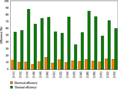
Since the appearance of PVT systems in the 1970s, different designs of heat exchangers have been developed, such as roller absorbers, flat-box absorbers, parallel-flow channels, pancake absorbers, modified serpentine, strip absorbers, direct-flow channels, flat-box designs with rectangular channels, oscillating-flow absorbers, spiral-flow absorbers, and others. Among these models, spiral and serpentine exchangers are the most commonly used. Figure 47 illustrates the electrical and thermal performance of the various designs mentioned above, providing an overview of the performance of existing PVT systems. The electrical and TEs of PVT systems with different heat exchangers ranged from 7.56% to 17.79% for electrical performance and from 36.32% to 87.72% for thermal performance. However, this comparison remains uneven, as efficiencies from different studies cannot be directly compared due to variations in operating conditions, climatic conditions, design parameters, heat exchanger shape, and type of fluid used.
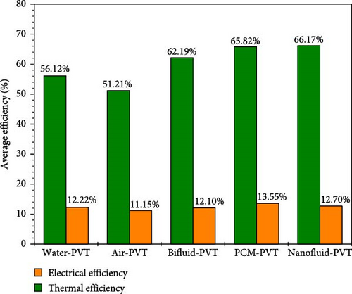
Different fluids have been explored in flat-plate PVT systems, including bi-fluids, water, air, PCM fluids, and nanofluids. Water-cooled systems offer superior performance to air-cooled systems. This is mainly due to the much higher specific heat of water, enabling better heat transfer and more efficient temperature management of PV panels. On the other hand, air-cooled PV systems are appreciated for their simplicity of design and ability to adapt quickly to a wide range of applications. Bi-fluid PVT systems, although still little explored, offer a significant advantage thanks to their ability to simultaneously produce electricity, hot water and hot air. This versatility overcomes the limitations of traditional systems, whether air- or water-based, by enabling more flexible use of the energy generated. According to the study by El Alami et al. [15], using PCMs with water achieved the best efficiencies. Moreover, systems using nanofluids also showed enhanced performance, as shown in Figure 48. These results make PVT systems cooled by MCP and nanofluids a recommended option for cooling PVT systems.
The use of modeling software has considerably advanced research into PVT systems, enabling reliable results to be obtained and complex scenarios to be simulated without the need for many physical experiments. Among the most commonly used tools, COMSOL Multiphysics and ANSYS stand out for their specific features. COMSOL is particularly well-suited to academic research and multiphysics studies, thanks to its flexibility and ability to handle models integrating different physical disciplines. It is, therefore, a preferred choice for rapid prototyping and exploratory analyses. On the other hand, ANSYS is more potent for complex industrial simulations, offering specialized solvers for structural mechanics and CFDs, making it a preferred choice for studies requiring high accuracy and computational performance. The choice of software, therefore, depends on the specific requirements of each study.
We make several recommendations for future research based on the analysis of the articles examined and the technologies discussed. Based on the gaps identified and the prospects for improving the systems studied, these recommendations are detailed in the section devoted to the conclusion and recommendations.
6. Conclusions and Recommendations
Current research into PVT systems technology focuses on two major areas: improving overall energy production and finding solutions to overcome the potential obstacles limiting the development of this technology, whether in terms of design or performance. As a general rule, the performance of PVT systems is strongly influenced by weather conditions. For this reason, during the design phase of these devices, designers rely on long-term meteorological data to select the appropriate materials for constructing the components. Adjustments to the heat transfer fluid also play a key role in the OE of this technology.
- •
The temperature of PV modules during operation plays a crucial role in the impact on the performance of PVT systems. A high PV temperature has a dual effect: it reduces electrical performance while improving thermal performance.
- •
The use of glazing in PVT systems has a significant impact. PVT systems fitted with glazing offer higher TE and OE, while unglazed PVT systems offer better EE.
- •
According to the study by Zondag et al. [55], it is preferable not to exceed three layers of glass in PVT systems. Beyond this limit, solar radiation transmission would be significantly reduced, even if TE improved.
- •
The PV cells used in PVT systems directly influence their performance. The various technologies available include monocrystalline, polycrystalline, thin-film, perovskite, and organic Si cells. Each type of cell has specific characteristics in terms of efficiency, cost, and behavior under different environmental conditions. It is, therefore, crucial to choose the right cell type for the particular requirements of the PVT system to optimize its performance and cost-effectiveness.
- •
The proper integration method to fuse thermal absorbers with PV modules is of paramount importance, as it directly affects the TE of a PVT system due to the existing thermal resistance between the PV modules and the thermal absorber. In this context, EVA is the optimal material for integrating the flat absorber with PV panels [36].
- •
In PVT systems, the material selected must, above all, be capable of ensuring efficient heat transfer. To maximize thermal performance, it is essential to choose materials with high thermal conductivity. This enables the system temperature to be reduced more effectively, improving heat management and optimizing the OE of PVT systems.
- •
PVT systems have shown that aluminum and copper are the best-performing materials, with a preference for aluminum because it is lighter and more affordable.
- •
The performance of PVT systems depends largely on the design of the absorber and the circulation channel system. Indeed, temperature distribution and cooling efficiency are influenced by several factors, including the spacing between the hollow tubes. Too wide a spacing can lead to uneven heat distribution, affecting system efficiency. On the other hand, a narrower spacing ensures better temperature uniformity. To guarantee optimum performance, it is essential that the design completely encompasses the surfaces beneath the PV panel.
- •
In PVT systems using water as a heat transfer fluid, a wide variety of heat exchanger configurations have been explored, such as spiral structures, parallel or rectangular channel absorbers, roller or corrugated plate devices, or oscillating flow models. Despite this diversity, a common problem persists: the temperature within the module is not evenly distributed, which affects the OE of the system. Furthermore, differences in experimental conditions, geometries adopted, materials used, and operating regimes make it difficult to establish a rigorous comparison between these different designs.
- •
In PVT systems, innovative fluids such as PCMs and nanofluids offer advantages far superior to conventional fluids. Not only do PCMs effectively regulate cell temperature by storing heat, but they also extend thermal output after sunset, thereby increasing energy availability. Their combination with water has achieved remarkable efficiency levels, approaching 98.78%. Nanofluids, for their part, enriched with high-thermal-conductivity particles, enhance heat exchange within the system, improving panel cooling and the stability of their electrical output. Both technologies enhance the overall performance of PVT systems, paving the way for more sustainable and efficient solutions.
- •
Simulation software, such as COMSOL Multiphysics, ANSYS, etc., is used to model, optimize, and analyze PVT systems. They are used to simulate temperature distribution, fluid flow, thermal and energy performance and to design more efficient PVT systems. These tools help engineers improve the design of PVT systems and evaluate their performance before manufacturing.
Flat-plate PVT systems present a wide range of practical applications in various energy sectors, thanks to their ability to simultaneously generate electricity and heat from solar energy. In the domestic sector, they provide hot water, reduce heating and electricity costs, and limit CO2 emissions. In agriculture, they are used for crop drying, greenhouse heating, and irrigation thanks to solar pumping, promoting efficient energy and economic management. In industry, these systems meet thermal needs for low-temperature processes while powering electrical equipment, helping to reduce costs and decarbonize operations. Finally, tertiary buildings provide space heating and electrical power while optimizing the use of roof space. These systems offer significant economic advantages by reducing dependence on fossil fuels and environmental benefits by actively reducing polluting emissions.
- •
In PVT systems, uneven temperature distribution between well-cooled and less-cooled areas can lead to internal thermal stresses. If these differences persist over the long term, they are likely to accelerate the degradation of PV cell materials. It would, therefore, be useful to study these thermal gradients in greater depth in order to assess their impact on the operational life of modules and optimize design to limit these differences.
- •
In many current PVT system configurations, although heat exchanger cooling improves overall performance, some specific areas, such as those near the panel’s electrical box, remain significantly warmer. This thermal imbalance highlights a design flaw in the distribution of the heat transfer fluid or in the extension of the exchange surfaces. To remedy this, it is crucial to carry out further work on the internal configuration of exchangers to eliminate these hot spots and ensure a uniform temperature across the entire surface of the panel, contributing to both better performance and greater system durability.
- •
Currently, there is a lack of commercially available PVT systems, which limits the competitiveness of the systems. However, optimizing PVT systems remains essential to increase their cost-effectiveness and autonomy, thereby meeting the growing demand for energy in various applications. This optimization is primarily based on the structure of PVT systems, which significantly influences their performance and cost. More efficient PVT systems need to be developed to bring these systems to market more quickly.
- •
It is important to carefully analyze the materials employed in the heat exchangers of PVT systems, whether polymeric or metallic. The hot water generated by these systems, often employed in domestic applications such as showers or heating, could be contaminated by residues of these materials, leading to health problems such as skin disease or irritation. To guarantee user safety, it is, therefore, advisable to test the compatibility of these materials with drinking water and assess their impact on health to ensure the risk-free operation of PVT systems.
- •
No current heat exchanger design allows direct contact between water and PV cells. Therefore, new heat exchanger designs should be developed and proposed to enable this direct contact to improve heat transfer and the OE of PVT systems.
- •
It is suggested that MMCs be explored as substitutes for conventional metals and their alloys in the design of absorbent tubes.
Nomenclature
Letters
-
- G:
-
- Solar irradiance (W/m2)
-
- V:
-
- Voltage (V)
-
- Voc:
-
- Open-circuit voltage (V)
-
- Isc:
-
- Open-circuit current (A)
Abbreviations
-
- PVT:
-
- Photovoltaic thermal
-
- PV:
-
- Photovoltaic
-
- STCs:
-
- Solar thermal collectors
-
- FR:
-
- Flow rate
-
- EE:
-
- Electrical efficiency
-
- TE:
-
- Thermal efficiency
-
- OE:
-
- Overall efficiency
-
- PCM:
-
- Phase change material
-
- IEA:
-
- International Energy Agency
-
- MMC:
-
- Metal matrix composite
-
- CO2:
-
- Carbon dioxide
-
- UV:
-
- Ultraviolet
-
- EVA:
-
- Ethylene-vinyl acetate
-
- Si:
-
- Silicon
-
- GaAs:
-
- Gallium arsenide
-
- m-Si:
-
- Monocrystalline silicon
-
- CIGS:
-
- Copper indium gallium selenide
-
- a-Si:
-
- Amorphous silicon
-
- CdTe:
-
- Cadmium telluride
-
- p-Si:
-
- Polycrystalline silicon
-
- PET:
-
- Polyethylene terephthalate
-
- PVB:
-
- Polyvinyl butyral
-
- PDMS:
-
- Polydiméthylsiloxane
-
- TPT:
-
- Tedlar–polyester–stellar
Subscripts
-
- oc:
-
- Open-circuit
-
- sc:
-
- Short-circuit.
Conflicts of Interest
The authors declare no conflicts of interest.
Funding
The authors received no specific funding for this work.
Open Research
Data Availability Statement
The data that support the findings of this study are available on request from the corresponding author. The data are not publicly available due to privacy or ethical restrictions.


