SoC–Based Inverter Control Strategy for Grid-Connected Battery Energy Storage in AC Microgrid
Abstract
The successful integration of battery energy storage systems (BESSs) is crucial for enhancing the resilience and performance of microgrids (MGs) and power systems. This study introduces a control strategy designed to optimize the operation of BESSs. This control strategy optimizes the BESS operation by dynamically adjusting the inverter’s power reference, thereby, extending the battery cycle life. This approach incorporates a droop control mechanism that adjusts control actions in response to state-of-charge (SoC) fluctuations of the BESSs, thereby, enhancing system performance. The effectiveness of this SoC–based control strategy is demonstrated through Matlab/Simulink. It shows its capabilities in regulating power, voltage, grid synchronization, and stability. The paper utilizes a modified CIGRE MG benchmark for system evaluation. It presents case studies to demonstrate the effectiveness of the proposed control modifications. Additionally, a comparative analysis with a power–voltage (P–V) control strategy is presented. This analysis highlights the advantages of the proposed strategy in ensuring stable voltage regulation within the MG. This research provides a robust foundation for future developments in optimizing BESS integration. It offers a roadmap to advance the efficiency, reliability, and longevity of battery-based solutions in the evolving landscape of sustainable energy systems. Additionally, it sheds light on the potential for scalability and applicability across diverse MG configurations and operational scenarios.
1. Introduction
The rising global energy demand causes rapid concerns about the environmental impact of utilizing fossil fuels to generate electricity [1]. New regulations and policies have been implemented to reduce emissions of CO2 and other gases. As renewable energy sources (RESs) can help cut greenhouse gas emissions and fossil fuel, many such RESs have been integrated into electricity systems worldwide [2, 3]. However, RESs are intermittent, posing challenges to the power system’s stability and quality [4, 5]. Therefore, there is a need for effective energy storage and management solutions that can balance supply and demand, hence, enhancing the resilience and performance of the power system.
As a promising solution to such a challenge, battery energy storage system (BESS) can store excess energy during low-demand periods and supply it during peak demand [6, 7]. BESS can also provide ancillary services, such as peak shaving, voltage support, frequency regulation, and renewable energy integration [8, 9]. The global cumulative electrical energy storage capacity has significantly increased over time, specifically during the last decade [10, 11]. For instance, the storage capacity has grown substantially between 2015 and 2022, with the cumulative capacity reaching 48.8 gigawatts in 2022 [10]. However, the operation of BESS might be challenging, as it requires careful management and control of its state-of-charge (SoC), which reflects the remaining energy capacity of the BESS. Moreover, SoC affects the battery’s performance, efficiency, and lifespan; thus, it should be appropriately managed [12]. Droop control methods are common for managing power flow between the BESS and the grid [13–15]. By mimicking the behavior of the synchronous generators, droop control enables the decentralized and autonomous operation of multiple inverters in a microgrid (MG) [16]. The droop control adjusts the active and reactive power of the inverter in response to deviations in grid voltage or frequency from their nominal values. Regardless of the advantageous properties of such control, most of the existing droop control strategies do not consider the SoC of the BESS, which may lead to suboptimal performance and reduced battery life. Neglecting the SoC of the BESS in droop control strategies can result in inefficient power management, decreased system performance, and accelerated battery degradation.
Some earlier studies on droop-based control techniques included the SoC of BESSs [17–22]. In [17], a droop control strategy is presented to achieve SoC balance among multiple energy storage units with varying capacities in an islanded AC MG. Another novel SoC–based droop control method is proposed in [18] for BESS to facilitate coordinated operation of direct current (DC) MGs without requiring communication links. This approach combines droop control with a DC bus signaling technique to effectively manage the DC bus voltage, thereby, preventing both overcharging and overdischarging of the batteries. On the other hand, a method for effective voltage restoring for DC MGs was suggested in [19]. It achieves accurate power-sharing and SoC balancing among distributed battery units.
For islanded DC MGs, Zeng et al. [20] and Belal, Yehia, and Azmy [21] present different decentralized control strategies. These strategies adjust droop coefficients depending on the SoC and battery capacity to achieve SoC balance, load current sharing, and bus voltage stability. Furthermore, a droop control method based on a virtual battery is suggested in [22] for a DC MG. This method dynamically adjusts the droop coefficient and the reference output voltage of the energy storage system based on its charge state. Additionally, the DC bus voltage level coordinates power-sharing among photovoltaic (PV) sources, the energy storage system, and the grid. The work presented in [23] focuses on SoC balancing, considering the small-signal stability of an AC MG. In addition to balancing the SoC level, a control strategy to share reactive power is presented in [24].
While these approaches have made valuable contributions to BESS control strategies in MGs while considering the SoC, it is essential to note that most of the research has only focused on DC MGs. In addition, the main focus was balancing the SoC level without consideration of injected active and reactive power. Hence, more exploration of SoC–based control strategies dedicated to AC MGs remains to be addressed. Additionally, most SoC–based strategies in AC MGs concentrate on achieving balance without optimizing energy utilization [25, 26]. Therefore, this study tries to bridge this gap by shedding light on implementing an inverter control strategy explicitly tailored to manage BESSs efficiently inside an AC MG by considering the variation SoC level. The proposed approach utilizes a droop control strategy to adjust the reference power of the BESS-fed inverter, potentially enhancing the battery’s cycle life, state of health, and remaining useful life by managing the SoC [27, 28].
Another key contribution of this work is to optimize the energy utilization of the battery through SoC–based active and active power control, thereby, enhancing the efficiency and sustainability of AC MGs. This optimized energy utilization in a MG might limit greenhouse gas emissions, lower its dependency on fossil fuels, and increase overall system resilience and reliability. Moreover, the proposed strategy prevents the BESS from overcharging or overdischarging, mitigating potential battery damage, and extending its lifespan. Therefore, this approach contributes to long-term resilience and the reliability of AC MG systems that comprise energy storage units, paving the way for more sustainable and intelligent energy solutions. The effectiveness of the suggested control method is evaluated by several operation scenarios simulated in Matlab/Simulink using a MG benchmark model, providing a comprehensive evaluation of its performance and applicability within an AC MG context.
The rest of the paper is organized as follows: Section 2 presents the control methodology of the grid-connected inverter used to interface the BESS to MG. Section 3 describes the SoC–power droop controller characteristics. Section 4 describes the simulated system configuration. The main results of the simulated scenarios are displayed and discussed in Section 5. Section 6 presents the main results of implementing a power–voltage (P–V) droop controller. Finally, Section 7 provides the paper’s conclusions.
2. Grid-Connected Inverter Control Scheme
2.1. Inverter Control Strategy for BESS
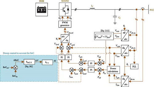
The proposed control strategy is aimed at optimizing the performance of BESSs within the AC MG. The control scheme employs a closed-loop current controller implemented using a synchronous reference frame (SRF), as illustrated in Figure 1. A reduced-order average model of the inverter is adopted here for efficient computation and accurate presentation [29]. This might be justified by assuming that the switching frequency significantly exceeds the grid frequency. The dq-measured components (Vd,m, Vq,m, Id,m, and Iq,m) are obtained through Clarke and Park transformations [30, 31] with the help of a phase-locked loop (PLL). This transformation allows applying a proportional-integral (PI) controller to achieve a specific reference value with zero steady-state error. Furthermore, a decoupling between active and reactive power components is attained. The current components of the dq-frame can be represented by:
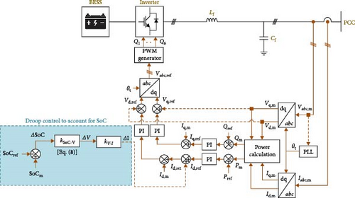
Here, k2p and k2i denote the proportional and integral gains of the second PI controller, which adjusts the reference voltage to minimize the error between the desired and measured currents. Finally, the reference voltage is transformed into the abc-reference frame and sent to the pulse width modulation generator. This pulse generator produces gate pulses to control the inverter’s power electronic switches, enabling precise control of the BESS output.
2.2. Importance of SoC Consideration in the Control Loop
A control strategy that does not explicitly account for the SoC of the BESS can lead to suboptimal performance and potentially affect the battery’s lifespan [27]. It is worth pointing out that the control system may lack awareness of critical BESS states, such as potential depletion, if it does not account for the SoC [35]. In other words, this absence of information can lead to suboptimal power flow management and potentially impact the overall system stability. In particular, the secondary control responsible for power flow may not receive vital information about the battery’s depleting state, hindering efficient energy utilization. To address this limitation, the proposed control strategy is enhanced by incorporating a SoC–based droop control loop, as explained below.
2.3. Control Strategy Incorporating SoC
Note that Equation (10) ensures that any changes in BESS voltage due to variations in SoC would be appropriately reflected in the reference DC, thus, optimizing the control strategy’s response to dynamic grid conditions. Additionally, a reactive power limit is enforced at low real power output levels to maintain the inverter’s power factor, thereby, enhancing grid stability under varying operating conditions [36].
3. SoC–Power Droop Characteristic
This section uses the suggested control technique to examine the SoC–power droop curve of a BESS connected to the grid via an inverter [32]. A complete discharge cycle is undergone by a single inverter at a rate of 10% per hour, which in the simulation corresponds to a 1-s interval.
To protect the BESS and ensure its expected lifespan, a specific limit for the output power is defined in this study [37]. Inverter disconnection occurs when the SoC falls below its lower limit at 35% [38]. Additionally, to maintain system power balance and stability, the nominal output power remains constant at the nominal capacity when the SoC exceeds 85% [28]. Moreover, the SoC range can be fine-tuned based on the particular battery specifications, configuration, and technology using the approach outlined in [39]. The SoC–voltage relationship, characterized by a slope denoted as KSoC-V, is depicted in Figure 2a.

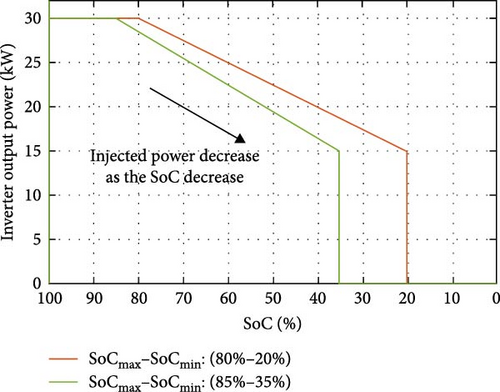
Two simulations are conducted with distinct SoCmax and SoCmin values: 80% and 20% for the first and 85% and 35% for the second. Figure 2b illustrates the correlation between SoC and power for both scenarios. These results provide a visual representation of the SoC–power droop behavior.
4. System Configuration
For this study, the CIGRE MG system benchmark is considered. This benchmark is a robust foundation for investigating control features of grid-connected inverters in BESS applications [40, 41]. CIGRE’s primary focus on low-voltage distribution networks aligns well with the comprehensive examination of various aspects of power systems, particularly within the intricate field of MGs [42].
The CIGRE MG system is designed to incorporate a primary feeder featuring a variety of distributed energy resources, including PV panels, wind turbines, and BESSs. To align with the specific objectives of this research [32], a modified version of this benchmark is employed, as depicted in Figure 3. The system configuration includes four distributed loads totaling 202 kVA, streamlining the system’s complexity. Additionally, two BESS units, each rated at 30 kW, are integrated into the configuration.
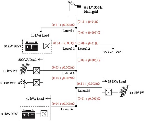
The electrical grid is designed to accommodate the demands of the remaining loads. Furthermore, utilizing information from [40], the impedance properties of each lateral, as well as the main feeder (per phase), are presented to provide a comprehensive understanding of the system’s electrical characteristics.
5. Simulation and Performance Evaluation
This section includes the simulation of the proposed control system that is evaluated within the modified AC MG benchmark setup featuring two BESSs, as illustrated in Figure 3. The simulation model aims to offer valuable insights into the effectiveness of the suggested control system, focusing primarily on BESSs and their interactions within the simplified MG.
- •
The inverter is considered lossless, with Pac equal to Pdc.
- •
The BESS is in the discharging mode of operation.
- •
The system follows the secondary control set points throughout the simulation.
- •
One hour of simulation time is equivalent to 1 h of real-world time.
The proposed modifications to the control system are implemented and evaluated using a steady-state snapshot [43]. Initially, the system undergoes simulation for 1 s, after which the droop system is engaged to counteract any transient effects arising from BESS operations that might impact the outcomes. Observe Table 1, which provides essential system and BESS parameters for the simulation study, covering a wide range of information on MG components, load characteristics, grid settings, and BESS characteristics.
| Parameters | Value | Parameters | Value |
|---|---|---|---|
| Grid voltage L-L (V) | 400 | Load 1–active power (kW) | 14.7 |
| Grid frequency (Hz) | 50 | Load 1–reactive power (kVAR) | 2.98 |
| Grid resistance (Ω) | 0.15 | Load 2–active power (kW) | 73.5 |
| Grid inductance (mH) | 0.127 | Load 2–reactive power (kVAR) | 14.925 |
| Filter reactive power (kVAR) | 6 | Load 3–active power (kW) | 17.64 |
| The BESS’s nominal voltage (V) | 400 | Load 3–reactive power (kVAR) | 3.58 |
| SoC-V droop coefficients (1/V) | 1/3 | Load 4–active power (kW) | 46.06 |
| V–I droop coefficients (A/V) | 3 | Load 4–reactive power (kVAR) | 9.3 |
- Abbreviations: BESS, battery energy storage system; SoC, state-of-charge.
5.1. Case I: MG With Fixed Power References for Batteries
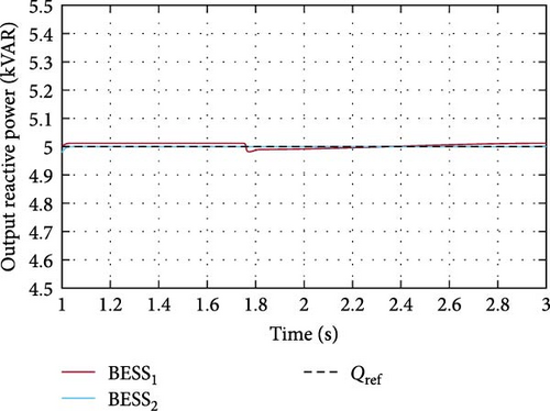
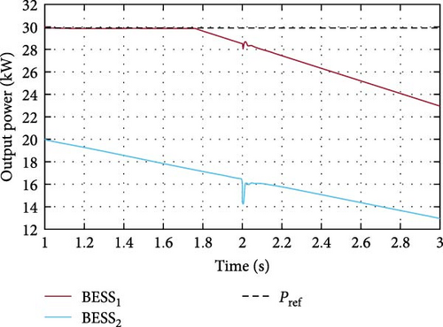
In this scenario, the reference active power (i.e., Pref) for the two BESS-fed inverters is set to 30 kW, while reactive power reference (i.e., Qref) is set at 5 kVA. The controller of each inverter matches the proposed control scheme shown in Figure 1. Regarding the initial SoC of each unit, BESS1 starts at 100% SoC, while BESS2 is at 60%. Figure 4 illustrates the injected active and reactive power profiles during the simulation. BESS1 initially provides 30 kW and gradually declines at around 1.8 s when its SoC hits 85%. On the other hand, BESS2 starts at approximately 20 kW and then decreases progressively. The controller introduces the lower starting point of BESS2 to avoid overdischarging the unit. Both inverters consistently inject 5 kVAR of reactive power, showcasing effective reactive and active power decoupling.
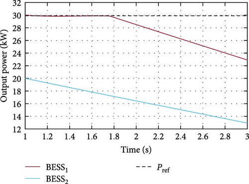
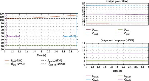
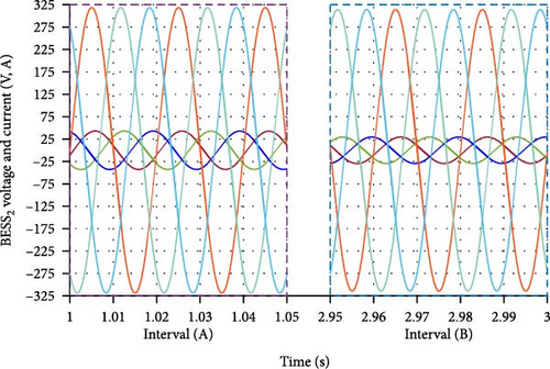
Additionally, the simulation results offer valuable insights into the practical implementation of the proposed control strategy, demonstrating its ability to ensure uninterrupted power supply to the loads by effectively managing BESS active power in response to a diminishing SoC. Figure 5 displays the output power profiles of the loads and the grid. As BESS active power drops due to diminishing SoC, the grid supplies the required energy to the loads, ensuring an uninterrupted power supply. In Figure 6, the plot illustrates the voltage and current waveforms for BESS2, which confirms a consistent synchronization of voltage and current waveforms throughout the simulation. Notably, a decline in current is evident during the second interval, in comparison to the initial interval, due to the decrease in active power level.
By optimizing the performance of BESSs within MGs, the proposed strategy has the potential to unlock substantial economic benefits, including cost savings through efficient energy utilization and revenue generation from ancillary services provision.
5.2. Case II: MG With Step Change in Inverter Power Reference
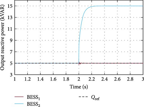
In this case, the reference reactive power of BESS2 will shift from 5 to 15 kVAR at t = 2 s. The injection of reactive power might be required for voltage regulation in the MG. Note that both BESS units commence with the identical initial SoC as the initial scenario. However, following the introduced step change, the reactive power is swiftly adjusted to its new reference values, as depicted in Figure 7. This behavior demonstrates the potential role of the control strategy in ensuring grid voltage stability. It is noteworthy that the active power generated by both inverters remains unaffected. Thus, active power delivery demonstrates the strategy capability to seamlessly manage varying reactive power requirements while ensuring a stable and consistent active power supply.
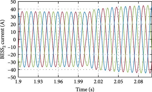
The introduced step change in the reactive power reference at t = 2 s leads to a noticeable transition in the current waveform, as shown in Figure 8. The displayed current waveform highlights the dynamic response of the system to modifications in the reactive power output of the BESS. These results highlight the effectiveness of the control method and its capacity to quickly adjust to changes in reactive power demands, while maintaining the MG’s active power demand. By optimizing energy utilization, this control strategy can reduce wear and tear on batteries, prolonging their operational lifespan and reducing the frequency of replacements [41]. Moreover, the implementation of this strategy could lead to some crucial environmental benefits, such as reduced greenhouse gas emissions and increased penetration of RESs, aligning with global sustainability objectives.
5.3. Case III: MG With Active Power Control for Near-Depleted Batteries
This case is aimed at assessing a critical safety measure where the battery’s stored energy is nearly depleted. Here, both inverters are set to an active power reference of 30 kW and a reactive power reference of 5 kVAR. Note that the initial battery charge levels are set to 80% for the first and 50% for the second battery to allow evaluation of the inverter’s capability to disconnect a battery as it approaches its lower SoC limit. Figure 9 provides insights into the power output of each BESS and illustrates the moment when BESS2 is disconnected from the system. This disconnection occurs after 2.4 s of simulation time as BESS2 reaches its minimum SoC limit, set to 35%.
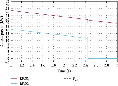
This protective measure prevents overdischarge, preserving the battery’s operational integrity and longevity. It is worth noting that this lower limit depends on the battery technology, and hence, can be easily adjusted in the proposed control scheme. Furthermore, the simulation results underscore the importance of implementing protective measures to prevent overdischarge of batteries, ensuring their operational integrity and longevity.
6. Active Power–Voltage Control Strategy
In contrast to the conventional P–Q control scheme, which primarily relies on active and reactive power as control parameters, the active power–voltage (P–V) control scheme adopts a different strategy. In this approach, predetermined values are assigned to the inverter’s active power reference (Pref) and output voltage reference (Vref), serving as fixed points for the control strategy. The control mechanism now entails adjusting the injected reactive power to align with these reference values. Consequently, the inverter regulates the output reactive power to meet the specified voltage reference (Vref). This responsive adjustment to variations in active power demand and voltage conditions renders the P–V control scheme highly flexible and efficient in overseeing grid interactions.
The P–V control scheme offers key advantages for grid-connected systems and MGs [44, 45]. It enhances voltage regulation, eliminates the need for reactive power compensation devices, and enables semiautonomous MG operation. This strategy improves stability and dynamic performance through a secondary control loop. Notably, it excels in adapting to rapid load changes, maintaining active power at the specified reference while dynamically adjusting reactive power for voltage stability, which is ideal for MGs with dynamic load profiles.
The inverters’ reference output voltages (Vref) are determined using a power flow analysis on the system. Subsequently, a PI controller uses the deviation between this value and the real-time inverter voltage measurement (Vm) to compute the reference quadrature current (Iq,ref). The measured voltage is obtained by transforming the AC-side voltage into alpha–beta components, as depicted in Equation (11). Similarly, the reference DC (Id,ref) is obtained from the error signal between the measured and reference active power (Pm and Pref). Accounting for the battery’s SoC impact involves introducing a supplementary term to Id,ref, as detailed in the preceding section. Figure 10 visually illustrates a schematic of the improved control scheme.
The simulation results are presented to assess the effectiveness of the P–V control strategy. In the simulation, both inverters are configured with a reference active power of 30 kW, starting with an initial SoC of 100% for the first BESS and 60% for the second BESS. The reference output voltage per unit (p.u.) for both BESS units, determined based on power flow results for the benchmark, is 0.991 and 0.981233, respectively. Active power profiles exhibited by the BESS-powered inverters throughout the simulation are depicted in Figure 11, which are dynamically decreasing as SoC levels decrease.
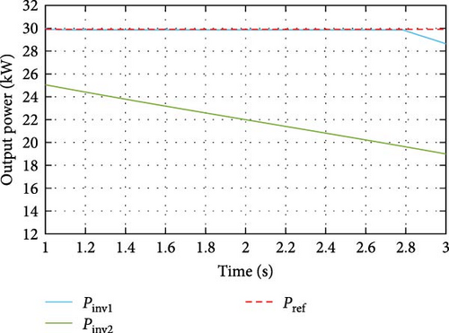
Figure 12 illustrates the measured and reference voltage profiles at the inverters’ output in p.u. for both control strategies. A stable voltage is maintained throughout the simulation in the P–V control strategy. In contrast, the P–Q control technique shows a proportionate voltage decrease in line with the decrease in the active power injection.
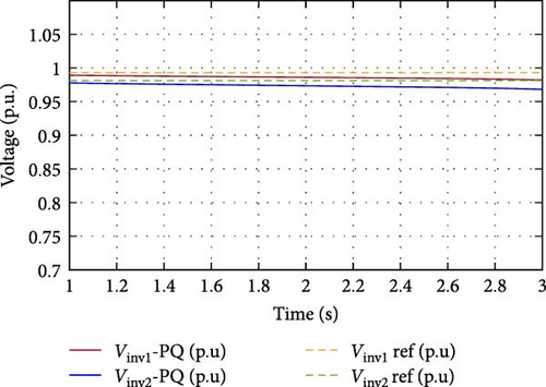
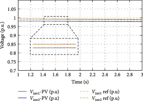
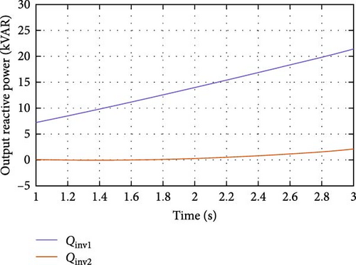
Figure 13 presents the reactive power profiles of both BESS-fed inverters, demonstrating dynamic adjustments to maintain reference voltage as active power decreases. This precise control ensures stable voltage regulation within the MG. Exploring the practical implications of these results in diverse real-world settings, including commercial, industrial, and residential sectors, can provide valuable insights into the scalability and versatility of the proposed strategy in addressing contemporary energy challenges.
7. Conclusions
This paper proposed a control strategy for integrating BESSs into MGs. By dynamically adjusting the inverter’s power reference based on the SoC of the BESS, the proposed strategy aims to optimize BESS operation, extend its cycle life, and improve the overall system stability. The results demonstrated the importance of considering SoC in the control scheme. SoC–based droop control loops were introduced to enhance the BESS performance. The work refines the control strategy to adapt to varying energy storage conditions. Simulation results using Matlab/Simulink based on the modified CIGRE MG benchmark revealed the effectiveness of the proposed SoC–based droop control strategy across various scenarios. These scenarios included a fixed power references case, showcasing effective active and reactive power decoupling, and ensuring uninterrupted power supply at different initial SoC levels. Step changes in the inverter’s reference power show the strategy’s quick adaptation to reactive power demands, while maintaining a stable active power supply. Furthermore, active power control disconnects the BESS when it approaches its lower SoC limit in a near-depleted battery scenario. The SoC–power droop characteristic provided a nuanced adjustment, showcasing adaptability to fluctuating SoC levels.
The P–V control strategy regulates voltage despite changing the SoC level by decreasing active power as the SoC level diminishes and adjusting reactive power. This approach offers advantages for maintaining voltage stability within MGs when changing active power loading. In addition, the results confirmed that the P–V control strategy ensured efficient energy utilization, which is crucial for the optimal operation of the MG. Potential applications of the proposed scheme include enhanced grid stability, economic benefits through efficient energy utilization, and extended battery lifetime. By optimizing energy utilization, this control strategy can reduce wear and tear on batteries, prolonging their operational lifespan and reducing the frequency of replacements [46]. This leads to cost savings and more sustainable battery use. Additionally, improved energy efficiency facilitates renewable energy integration and thus supports environmental goals such as the United Nations’ Sustainable Development Goal (SDG7), aiming to provide a clean and affordable energy resource. Moreover, the proposed strategy can enhance peak load management and reduce fossil fuel dependency. If integrated into smart grid applications, this strategy could enable advanced energy management and predictive maintenance and improving overall efficiency and resilience. For future direction, integrating charging cycles into the control strategy can improve system performance, further optimize energy management and extend the overall battery lifespan.
Conflicts of Interest
The authors declare no conflicts of interest.
Author Contributions
Conceptualization: Afaf Allabadi and Ibrahim Abuishmais. Software: Afaf Allabadi, Ibrahim Abuishmais, and Ayman Al-Quraan. Formal analysis: Afaf Allabadi and Ibrahim Abuishmais. Writing–original draft: Afaf Allabadi and Ibrahim Abuishmais. Writing–review and editing: Afaf Allabadi, Ibrahim Abuishmais, Qusay Salem, Rafat Aljarrah, and Ayman Al-Quraan.
Funding
This work was supported by Princess Sumaya University for Technology (Grant (10) 9-2023/2024).
Open Research
Data Availability Statement
The data are available on request.


