Optimal Design of Battery Energy Storage System Controllers for Damping Low-Frequency Oscillations
Abstract
Battery energy storage systems (BESSs) have recently been utilized in power systems for various purposes. Integrating these devices into power systems can enhance the damping capability of subsynchronous oscillations. The interaction between the control modes of the BESS and synchronous machines, as well as the control parameters of the BESS, reduces subsynchronous oscillations. To damp oscillations and improve dynamic stability, this work develops a linear model of a power system integrated with a BESS to investigate small-signal stability. The gain tuning of the BESS controller is formulated as an optimization problem and is solved using a fuzzy-based algorithm. The efficacy of the proposed method is evaluated under various operating conditions. Furthermore, the proposed method is compared with a power system stabilizer (PSS) damping controller, and the results demonstrate the superiority of the BESS damping method in mitigating subsynchronous oscillations and enhancing the dynamic stability of power systems. Lastly, eigenvalue analysis is employed to determine the permissible ranges of BESS parameters for stable power system operation.
1. Introduction
The increasing demand for electric power forces power systems to operate close to their stability limits. However, extending these limits is challenging due to environmental constraints and resource shortages. Consequently, the power transmission system in interconnected power systems is constrained by transient stability, voltage stability, and small-signal stability [1]. Moreover, power system resources are often geographically distant, which increases subsynchronous or low-frequency oscillations in the range of 0.2–3 Hz. Traditionally, generator local controllers such as governors and automatic voltage regulators (AVRs) have been used to mitigate this issue. However, due to their inherent time delays and limitations, power system stabilizers (PSSs) were developed to address low-frequency oscillations [2]. PSSs provide supplementary signals to excitation systems to generate electrical torque and reduce power oscillations. Nevertheless, PSSs may fail to perform effectively under certain conditions, such as heavy loading, poorly tuned parameters, and interarea oscillation modes [3, 4]. The integration of PSSs into power systems to damp low-frequency oscillations has been extensively studied in [5–7].
In recent years, advancements in the technical specifications of power electronic devices have made flexible alternating current transmission system (FACTS) devices one of the most effective methods for enhancing power system performance. FACTS devices can improve transient stability and reduce power system oscillations [8, 9]. For instance, Mushtaq and Mairaj-ud-din [10] presented a comprehensive approach that employs a thyristor-controlled series compensator (TCSC) combined with a fuzzy logic controller to enhance the damping of critical inter-area modes. However, integrating FACTS devices into power systems requires the coordination of their controllers with other generator local controllers to effectively mitigate power system oscillations. Numerous studies in the literature discuss various types of FACTS devices and their applications as power oscillation damping systems [11–15].
In addition to FACTS devices, HVDC systems can also serve as damping controllers. Furthermore, HVDC power controllers are faster and more adaptable compared to generator controllers. Research on HVDC damping controllers to mitigate interarea oscillations has been extensively conducted [16–19]. While HVDC systems can directly reduce interarea oscillations by regulating active power delivered through tie lines, they are primarily used to connect power grids across different regions. However, implementing HVDC systems often requires costly infrastructure upgrades compared to other damping methods. The increasing penetration of inverter-based renewable energy resources, such as photovoltaic systems and wind turbines, reduces the overall inertia of the power system. Nevertheless, these new resources and their associated technologies can provide virtual inertia and enhance oscillation damping in the power system by adjusting their controllers [20]. Despite challenges such as the intermittent nature of renewable energy resources, numerous studies, and approaches have explored their applications for damping low-frequency oscillations in power systems [21–24].
In modern power systems, energy storage systems (ESSs) are widely used for various purposes, including stability improvement [25, 26], enhancing system self-sufficiency [27, 28], frequency control [29, 30], power quality enhancement [31], and reliability improvement [32]. Although FACTS devices typically control reactive power, ESSs are versatile devices capable of injecting or absorbing active power into or from the power system instantaneously. Since low-frequency oscillations in power systems are influenced by active power oscillations, frequency oscillations can be more effectively suppressed by directly exchanging active power via ESSs rather than using PSS or FACTS devices [33]. Additionally, unlike renewable energy resources, ESS outputs are not intermittent. Consequently, ESSs have garnered significant attention for enhancing power system behavior and are considered as power oscillation damping devices in this study.
- •
Developing a linear model of a power system integrated with a BESS to investigate small-signal stability.
- •
Integrating a novel controller design for damping low-frequency oscillations using an adaptive fuzzy particle swarm optimization (PSO) algorithm.
- •
Conducting extensive analysis across varying load conditions to demonstrate the controller’s robustness and adaptability.
- •
Performing eigenvalue analysis to identify permissible parameter ranges for stable operation.
- •
Validating results in real time using Speedgoat, a rarely explored tool in similar studies, adding practical relevance to the findings.
The rest of this paper is organized as follows: Section 2 presents the nonlinear and Heffron–Phillips models of the BESS. Section 3 explains the optimal controller design and optimization algorithm. Section 4 discusses the simulation results and analysis of scenarios. Finally, the conclusions are presented in Section 5.
2. System Modeling and Formulations
Power systems, as complex dynamic systems, are described by nonlinear differential equations. To analyze power systems for aspects such as small-signal stability and low-frequency studies, state-space equations are employed [34, 35]. For this purpose, it is necessary to linearize the power system equations around an operating point [36]. Consequently, the initial nonlinear equations of the system under study are presented, followed by the formulation of the state-space equations.
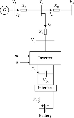
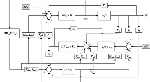
The block diagram of linearized model (Heffron–Phillips model) is shown in Figure 2.
Since the PSS [38] has been widely used to provide damping in power systems and is the most cost-effective approach to improving power system stability, its effect, along with the BESS, is analyzed in this study. A PSS is a control system applied to a generation unit, where its input is the angular frequency. The output of this controller is a control signal sent to the voltage regulator, which compensates for the phase lag between the exciter input and the machine’s electrical torque to damp oscillations in the output frequency. The block diagram of the PSS is shown in Figure 3.

In Figure 3, ∆ω shows the speed deviation, and UPSS is the output signal sent to the regulator of the excitation system. Tw is the washout filter time constant, while KPSS and T1–T4 represent the additional gain and the time constants of the lead–lag controller, respectively. The tuning of these parameters is performed to achieve acceptable damping capability in power systems.
3. Optimal Controller Design
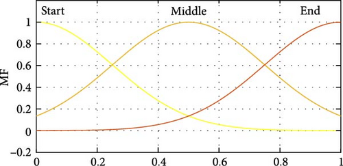
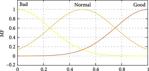
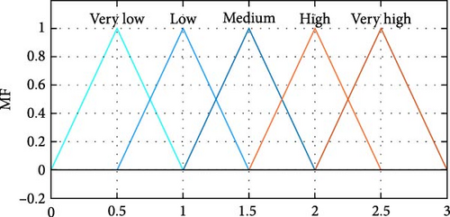
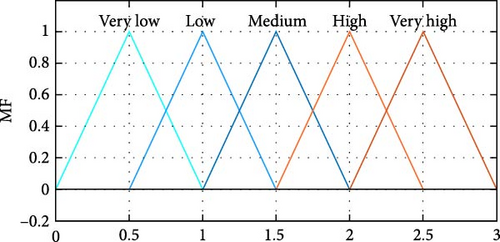
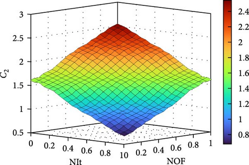
The outputs of the developed fuzzy system are local (C1i, t) and global (C2i, t) learning coefficients for the ith particle in tth iteration which are described by five triangular membership functions and are shown in Figure 5. In this work, to develop of the rule base, 2 × 9 IF-THEN rules have been considered and presented in Table 1. Moreover, the three-dimensional plot of embedded rules has been illustrated in Figure 6.

| C1 | C2 | ||||||
|---|---|---|---|---|---|---|---|
| NIt | NOF | NIt | NOF | ||||
| Bad | Normal | Good | Bad | Normal | Good | ||
| Start | Medium | Low | Very low | Start | Medium | High | Very high |
| Middle | High | Medium | Low | Middle | Low | Medium | High |
| End | Very High | High | Medium | End | Very Low | Low | Medium |
- Abbreviations: NIt, normalized iteration; NOF, normalized objective function.
4. Simulation Results and Discussion
-
Scenario 1: Stability analysis for fault disturbance in power under different operating conditions.
-
Scenario 2: Stability analysis for fault disturbance in voltage under different operating conditions.
-
Scenario 3: Comparison of the proposed approach with conventional controllers (PSS) for damping low-frequency oscillations.
-
Scenario 4: Investigation of the impact of BESS parameters on system stability.
-
Scenario 5: Real-time simulation and testing.
4.1. Scenario 1: Fault Disturbance in Power
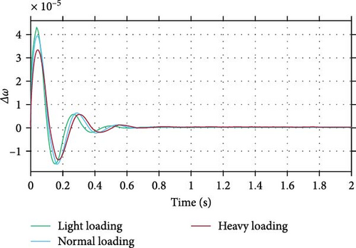
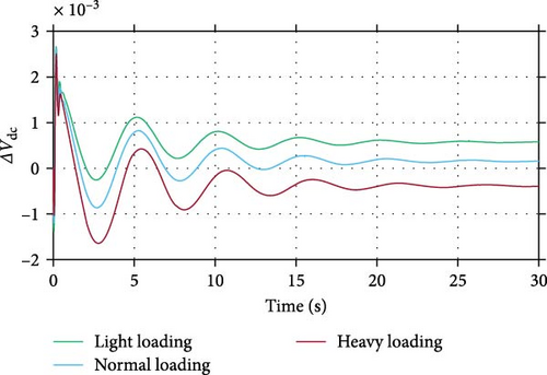
Figure 7 shows the dynamic responses of Δω after a fault disturbance in power in the presence of the optimal BESS controller under different loading conditions. It is evident that the designed controller provides effective damping for low-frequency oscillations and demonstrates robust performance across varying loading conditions. Figure 8 depicts the DC-side voltage of the BESS converter. As shown, the voltage varies at different operating points, with the BESS contributing significantly to mitigating oscillations.
4.2. Scenario 2: Fault Disturbance in Voltage
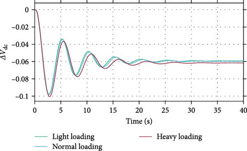
To verify the proposed optimal controller, a fault disturbance in voltage was also applied to the system. As shown in Figure 9, the system oscillations were effectively damped under various loading conditions. Figure 10 illustrates the DC-side voltage of the BESS for different operating points after the fault. In this figure, the voltage reaches a steady state following the fault, with the final value dependent on the loading conditions.

4.3. Scenario 3: Comparing BESS With PSS
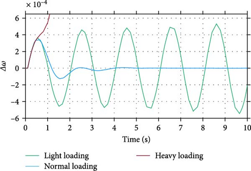
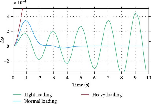
The PSS, an economical and effective controller, has been used for many years to enhance the damping of low-frequency oscillations. In this study, the proposed BESS is compared with the classical PSS. The optimal parameters for the PSS in the power system under study are KPSS = 200, Tw = 0.33, T1 = 0.01, T2 = 23.2, T3 = 261, and T4 = 25.7. As shown in Figure 11, the PSS can stabilize the power system only under normal loading conditions; the system becomes unstable at other operating points. In contrast, the proposed BESS demonstrates consistent performance across all operating points, from light loading to heavy loading. Similar results are observed after a fault disturbance in voltage, as illustrated in Figure 12.
4.4. Scenario 4: Investigating the BESS Parameters on Stability
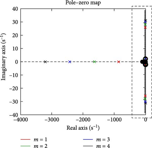
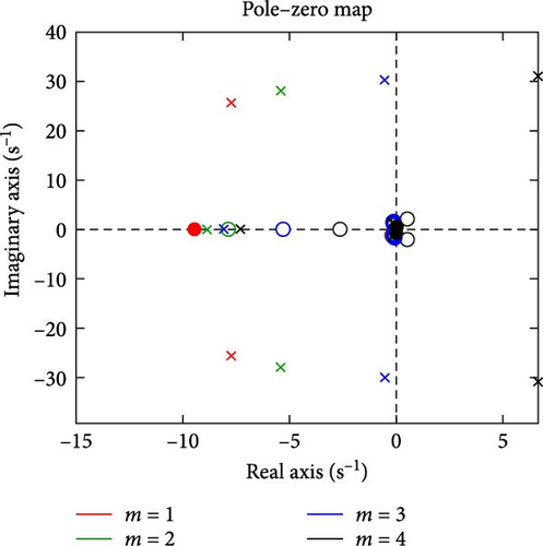
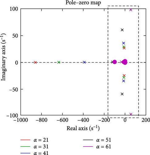
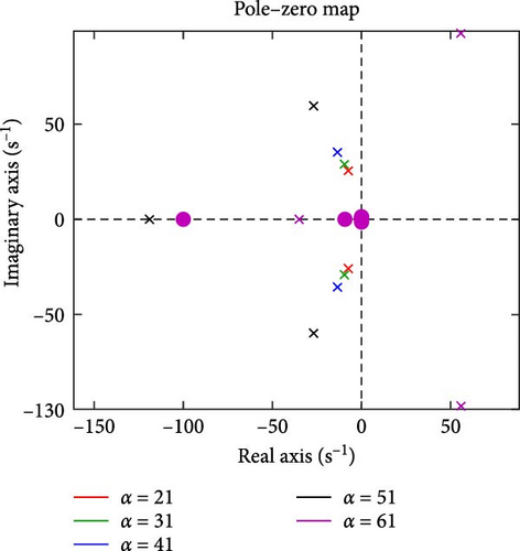
To investigate the impact of the proposed BESS on power system stability, the pole loci were plotted by varying the BESS parameters (m and α). First, m was increased from 1 to 4 while the other parameters remained unchanged. As shown in Figure 13, increasing m causes the poles to move toward the imaginary axis, indicating a slower response and a larger settling time due to a reduced damping coefficient. The black pole corresponding to m = 4 moves to the positive side of the zero–pole map, indicating that for values greater than 3, the system becomes unstable. Additionally, for m = 4, the zeros also shift to the positive side, meaning that a larger controller gain cannot stabilize the system. Next, α was increased from 21° to 51° while keeping the other parameters unchanged. Figure 14 shows that increasing α causes the poles to move away from the imaginary axis, resulting in a larger damping coefficient. However, further increases in α cause the pole direction to change. The magenta pole corresponding to α = 61° shifts to the positive side of the zero–pole map, indicating instability in the system 51°< α < 61°. Since all zeros remain on the negative side, a larger controller gain can stabilize the system in this case.
4.5. Scenario 5: Speedgoat—Real-Time Simulation and Testing
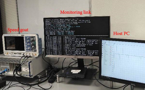
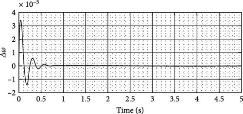
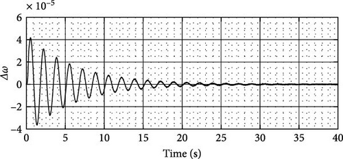
In this section, Speedgoat—real-time simulation and testing (Figure 15) has been performed to investigate the behavior of a physical system by running its simulation model. In this regard, the most severe operating condition means heavy loading has been considered and two fault disturbances in power and voltage are evaluated by using real-time simulation. Figures 16 and 17 show real-time simulation for ∆ω after a fault disturbance in power and voltage, respectively. The SpeedGoat real-time target machine, in conjunction with Simulink RealTime, offers an integrated solution suitable for exploring and instructing design principles across diverse fields such as mechatronics, motion control, power electronics, and signal processing. Serving as a robust platform for real-time simulation and testing, the real-time target machine comes equipped with essential cables, terminal boards, and adapters to facilitate seamless connectivity between the input/output (I/O) of the target machine and the hardware under examination [40]. Comprising two primary components, the SpeedGoat real-time system features a high-performance real-time target machine with an Intel 4.2 GHz i7 multi-core CPU (1), and an IO306-Performance Simulink-programmable FPGA I/O module (2). The IO306 incorporates a Xilinx Kintex-7 FPGA with 64 × 3.3V TTL I/O lines and a Xilinx Spartan 6 FPGA with 24 k logic cells. Simulink models can be automatically converted into code for either the CPU or FPGA using Simulink Real-Time or HDL Coder, respectively. Additionally, the Simscape Electrical model can be transformed into VHDL code using HDL Coder from MathWorks [41, 42].
5. Conclusion
- •
Investigating the nonlinear model of the power system.
- •
Developing a linear quadratic regulator (LQR) controller design.
- •
Exploring the application of machine learning methods to enhance precision and adaptability.
- •
Examining the interaction and coordination between the BESS and other renewable energy sources, such as wind and solar, to improve power system stability.
Conflicts of Interest
The authors declare no conflicts of interest.
Funding
This research received no specific grant from any funding agency in the public, commercial, or not-for-profit sectors.
Appendix 1
This appendix consists of supporting information for the proposed model. Table A1 shows K-constants of the Heffron–Phillips integrated with BESS for different operation points. The system steady state parameters are tabulated in Table A2.
| Parameter | Light loading | Nominal load | Heavy loading |
|---|---|---|---|
| Pe (pu) | 0.6 | 1.0 | 1.5 |
| Qe (pu) | 0.15 | 0.25 | 0.45 |
| K1 | 0.290 | 0.251 | 0.279 |
| K2 | 1.093 | 1.444 | 1.760 |
| K3 | 2.958 | 1.458 | 3.808 |
| K4 | 0.3214 | 0.246 | 0.269 |
| K5 | −0.052 | −0.045 | 0.059 |
| K6 | 0.444 | 0.533 | 0.384 |
| K7 | 0.284 | 0.243 | 0.169 |
| K8 | 0.0426 | 0.0436 | 0.0476 |
| K9 | −0.0038 | −0.0039 | −0.003 |
| Kpdc | 0.097 | 0.120 | 0.110 |
| Kpm | 0.443 | 0.501 | 0.556 |
| Kpα | 0.522 | 0.584 | 0.590 |
| Kqdc | 0.235 | 0.243 | 0.258 |
| Kqm | 0.290 | 0.251 | 0.279 |
| Kqα | 1.093 | 1.444 | 1.760 |
| Kvdc | −0.052 | −0.045 | 0.059 |
| Kvm | 0.444 | 0.533 | 0.384 |
| Kvα | 0.284 | 0.243 | 0.169 |
| Kdcm | 0.097 | 0.120 | 0.110 |
| Kdcα | 0.443 | 0.501 | 0.556 |
| Parameter | Value | Parameter | Value | ||
|---|---|---|---|---|---|
| Generator | M | 8 MJ/MVA | BESS | Vdc | 1 pu |
| D | 0 | Rb | 0.1 pu | ||
| Xq | 0.6 pu | C | 1 pu | ||
| Xd | 1 pu | m | 1 | ||
| X’d | 0.3 pu | k | 1 | ||
| T’do | 5.044 s | α | 21° | ||
| Ka | 10 | Ied | 0.1 | ||
| Ta | 0.05 s | Ieq | 0.1 | ||
| δ | 42° | Operation point | Pe | 0.912 | |
| ω | 120π | Qe | 0.277 | ||
| Transmission line | XT | 0.1 pu | Ed | 0.4041 | |
| Xn | 1 pu | Eq | 0.9493 | ||
| Xe | 0.3 pu | Itd | 0.6735 | ||
| Vt | 1.032 pu | Itq | 0.6736 | ||
| Ve | 1.02 pu | ||||
| Vn | 1 pu |
- Abbreviation: BESS, battery energy storage system.
Appendix 2
- 1.
The first state variable:
- 2.
The second state variable:
- 3.
The third state variable:
- 4.
The fourth state variable:
- 5.
The fifth state variable:
Open Research
Data Availability Statement
The data that support the findings of this study are available from the corresponding author upon reasonable request.


