Dynamics and Robust Synchronization of an Oscillator With Cubic and Signum Terms
Abstract
In recent years, there has been a marked surge in research focused on nonlinear oscillators. Among these, a particular emphasis has been placed on a class of oscillators distinguished by their concealed attractors, drawing considerable attention due to their unique characteristics. This paper delves into the exploration of an elegant oscillator belonging to this distinctive class. Despite comprising five terms and lacking equilibrium points, this oscillator displays remarkably intricate dynamics. The study covers various aspects such as chaos, hidden attractors, offset boosting, and notably, different strange attractors exhibited by this oscillator. Additionally, approaches involving synchronization for such oscillators are introduced. Apart from the presentation of the novel chaotic oscillator, the synchronization of a nominal and uncertain chaotic system is evinced by the sliding mode technique (super-twisting algorithm) in the first case, and a robust controller is synthesized, respectively. The appropriate Lyapunov functions are implemented in the two synchronization strategies leading to obtain suitable control strategies to achieve fast and accurate control laws. The respective simulations are performed along with the conclusions of this work.
1. Introduction
Oscillators constitute crucial components within electronic circuits, serving as sources for fundamental reference signals such as sine or squared waveforms. These oscillators find extensive application in signal generators employed for measurement and testing purposes [1]. Acquiring knowledge about diverse types of oscillators not only aids in selecting the most suitable variant for particular projects but also facilitates the creation and realization of innovative designs [2]. Notably, oscillators imbued with chaotic behavior have garnered significant attention due to their intricately complex dynamics [3]. The presence of chaos in oscillators has broad applications across a spectrum of fields, spanning from security and signal processing to the realm of mobile robotics [4–7].
A self-excited attractor commonly emerges in conventional oscillators through computational procedures. Upon detecting an unstable equilibrium, it becomes possible to derive a basin of attraction. In recent years, there has been a surge in the development of oscillators housing hidden attractors, where the basins of attraction are independent of equilibria [8, 9]. Investigating these hidden attractors necessitates specialized computational approaches, posing a considerable challenge in their determination [10]. Nevertheless, in practical applications, it becomes imperative to discern the presence of these hidden attractors to ensure that the system operates in accordance with the anticipated attractor [11, 12]. This identification serves to mitigate undesired system behaviors, thereby enhancing system safety and reliability.
In their study of nonlinear oscillators, researchers observed the presence of multiscrolls within attractors. These multiscrolls not only signified intricate dynamics but also showcased the practical applications of these oscillators [13]. As a result, a range of oscillators featuring multiscroll attractors has been developed. Furthermore, the existing literature has documented diverse methods for constructing multiscroll structures [14, 15]. For instance, Matouk et al. [16] employed the Caputo operator in their investigation of fractional multiscroll systems. Hu et al. proposed a 5D system that exhibited hidden attractors [17]. Memristor was a versatile component for creating multiscrolls [18]. Hyperchaos was observed by Vaidyanathan et al. [19]. Multiscroll oscillators were implemented in [20]. Li and Zeng reported multiple scrolls in a jerk system [21].
Synchronization of two dynamic systems possesses importance in many physical systems such as optical and mechanical oscillators; therefore, it is important to mention some research studies, considering that in this paper the synchronization of the elegant chaotic system presented in this research study is performed by a super-twisting sliding algorithm. It is worthy to mention that the super-twisting algorithm provides a higher order sliding mode synchronization proving that it is an efficient control/synchronization algorithm as validated by numerical experiments. In the following reference [22], the design of a synchronizer for a financial chaotic system is realized by means of an integral sliding mode controller, proving the validity of the synchronization strategy. Besides in papers such as [23], a microcontroller implementation of a fractional order chaotic dynamic system by the sliding mode is provided. Meanwhile, in [24], a fractional order sliding mode controller is used to stabilize a secure system communication system.
Another control synchronization technique used in this research study is performed by means of a robust controller/synchronizer for the uncertain elegant chaotic system. The type of uncertainty analyzed in this research study is based on parametric uncertainties, which is one of the most common uncertainties found taking into consideration unmodelled dynamics. For example, in [25], the synchronization is realized by means of a Chlodowsky approximator for the uncertainties found in this system. Then, in [26], the robust synchronization of financial chaotic systems is performed by considering unknown parametric uncertainties. Finally, in [27], a robust controller based on neural networks is proposed for the synchronization of chaotic systems by a generalized projective strategy.
- •
Chaotic optic systems.
- •
Chaotic electromagnetic systems.
- •
Chaotic kinetic chemical reactions.
- •
Chaotic mechanical systems and oscillators.
The following reference survey is illustrated in order to clarify and validate the implementations of the identified chaotic system that is presented in this research study, as well as to observe the several applications in which it can be applied. In addition to secure communications, the following literature publications support the applicability of these results in chaotic optic systems. For example, Ref. [28] describes the subharmonic path to chaos in a laser beam system. Reference [29] then shows hyperchaotic behavior in a three-ring mutually connected laser. Reference [30] shows how to create chaos in a laser with optical feedback.
References related to electromagnetic chaos include papers such as [31] that provide a bifurcation analysis and nonlinear dynamic analysis of active magnetic bearings under complex resonance. Then, in [32], it is shown that a single photon in a cavity electromechanical device causes instability.
Meanwhile, instances of chaotic chemical reactions may be found in articles such as [33] oscillations and chaos in a chemical process incorporating heterogeneous catalysis. Then, in [34], kinetic chaotic responses are thoroughly examined. Last but not least, papers on the dynamic analysis of chaotic mechanical systems and oscillators, such as [35–38], provide fascinating findings that might be used in the ongoing study.
Finally, the next three sources are noteworthy due to the applications of chaotic dynamics. For example, Ref. [39] describes the nonlinear dynamics of three-layer microplates, while Ref. [40] offers a special adaptive filtering for cooperative localization. Lastly, Ref. [41] introduces the adaptive pseudoinverse control for constrained hysteretic nonlinear systems.
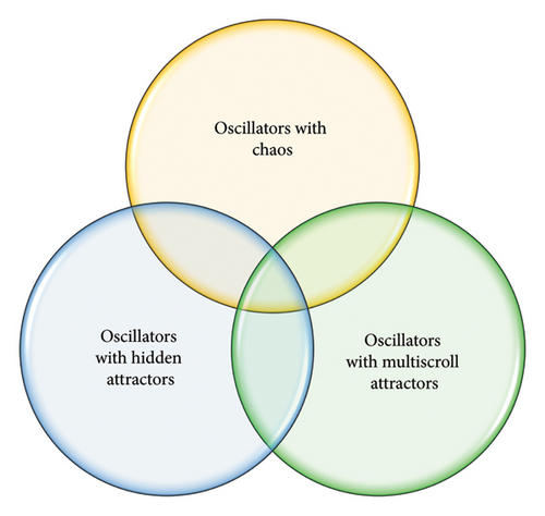
Our studied oscillator is not only simple but also has distinct features. The oscillator exhibits chaos, hidden attractors, offset boosting, and different strange attractors. In addition, the synchronization approaches have been developed for robust synchronization. They are useful for application scenarios such as mobile robot coverage path planning or chaotic path synchronization. The accuracy and stability during the path planning process are maintained despite the presence of uncertain disturbances. Figure 1 illustrates three discussed types of special oscillators. Our proposed oscillator, distinguished by its unique features, is prominently positioned at the center of Figure 1, where it intersects with three different types of oscillators. Notably, our oscillator exhibits elegance in comparison to previously published works, as illustrated in Table 1. The oscillator and its dynamics are explicated in Sections 2 and 3. Sections 4 and 5 delve into a comprehensive exploration of synchronization for this distinctive oscillator. The concluding section synthesizes the findings and implications, offering a comprehensive closure to our work.
2. An Elegant Oscillator

3. Dynamics of the Oscillator
3.1. Chaotic Attractors
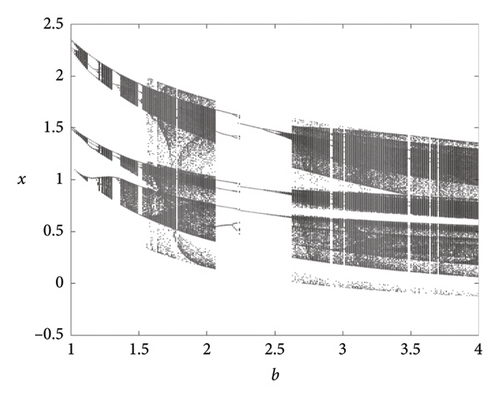
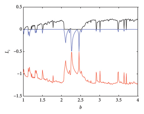
Dynamics of the oscillator is shown in Figure 4 via the bifurcation diagram and Lyapunov exponents for b. We applied Wolf’s method to calculate the Lyapunov exponents [43]. The nonsmooth term sgn(y) was replaced with the smooth approximation tan h(Ky), where K = 500 [44]. Chaotic and nonchaotic behaviors are observed for b ∈ [1, 4].
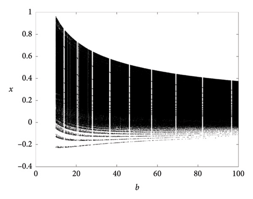
Interestingly, the value of b can be varied in a large range as illustrated in Figure 5.
3.2. Strange Attractors
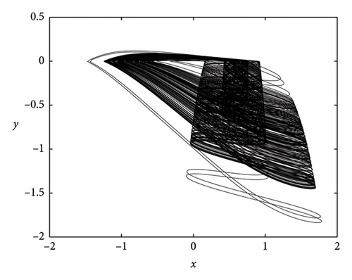
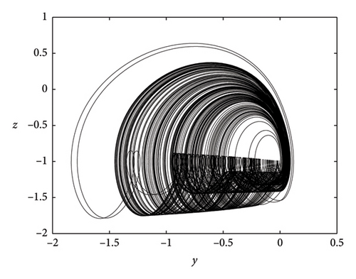
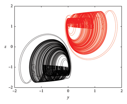
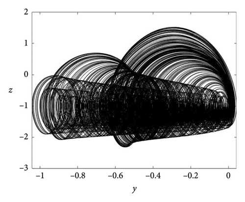
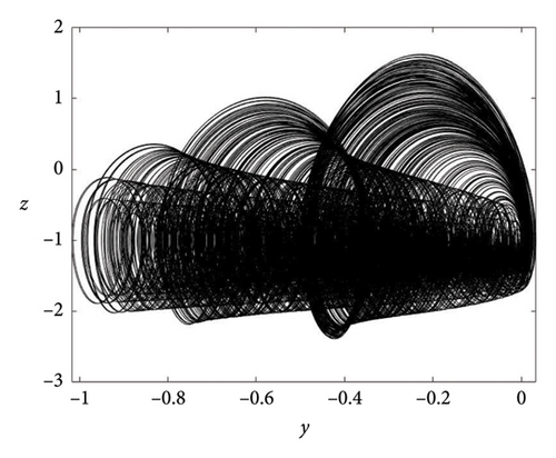
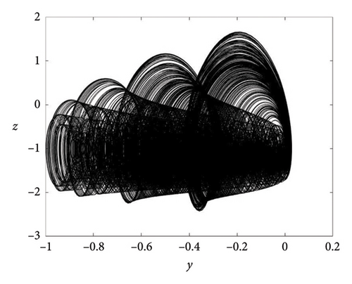
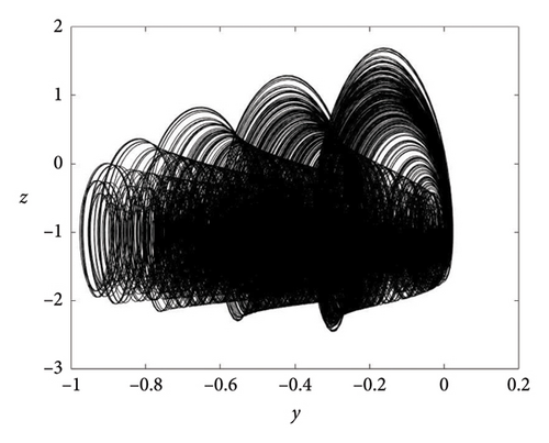
The literature has confirmed the association between strange attractors and equilibria. However, an intriguing aspect is the presence of strange attractors within oscillators featuring hidden attractors. Our proposed oscillator lacks equilibrium but demonstrates the capability to generate different strange attractors, as depicted in Figure 6. Notably, the number of shapes can be effortlessly manipulated by adjusting a single parameter, b, offering considerable flexibility. It is important to highlight that, typically, achieving different strange attractors necessitates the introduction of additional elements.
3.3. Offset Boosting
4. Synchronizer Design for the Elegant Oscillator
- •
Problem statement and formulation.
- •
Super-twisting sliding mode control synchronization strategy for the elegant oscillator.
- •
Numerical simulation.
The main objective in this section is to design the appropriate robust control synchronization strategy in order to synchronize the response system with the drive system. The chaotic dynamic systems in this case are considered in the nonuncertain form, so in this way, the synchronization is achieved by considering only the nominal systems. As explained before, the main purpose is to synchronize the two identical chaotic systems in order to obtain the maximum advantages for applications such as secure communications, electromagnetic chaos, and chaos found in artificial electrical and mechanical systems. Considering that this is a novel discovered elegant oscillator is necessary to design the appropriate control strategies for synchronization purposes for future implementations.
4.1. Theoretical Framework
4.2. Super-Twisting Sliding Mode Control Synchronizer
This strategy has been proven to be effective for synchronization control. The super-twisting sliding mode algorithm, as it is known, is an appropriate control strategy, as it is fast and minimizes the chattering effect caused by the oscillatory dynamics of the chaotic systems, so there is no problem for a physical synchronization implementation in mechanical, electrical, or chemical systems, for example. The following theorem establishes the control law for synchronization purposes based on the work of [46]:
Theorem 1. Consider the following super-twisting algorithm [46]:
4.3. Experimental Results
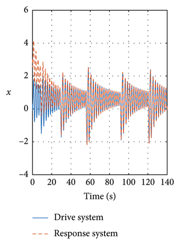
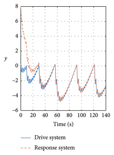
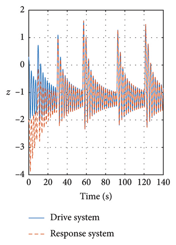
The initial conditions are X = [0.3, 0.2, 0.3]T. For the response system, the conditions are Y = [3, 8, −2]T with the following constants for both systems a = 2, b = 2, and c = 1.
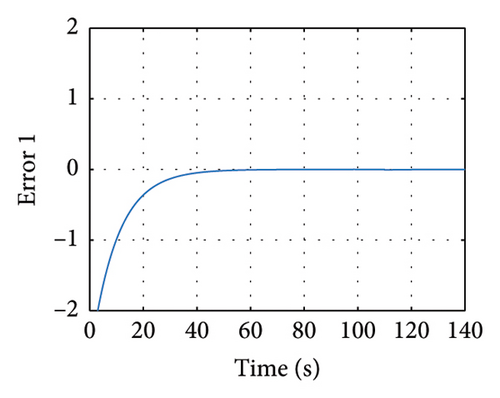
In Figures 8 and 9, the variables X and Y are presented, in which it is noticed how the three state variables are stabilized accurately. It is noticeable that as long as the gain matrices must be positive definite diagonal, the synchronicity is ensured. It is important to mention that the super-twisting sliding mode controller ensures that the error variables are driven to the origin in finite time.
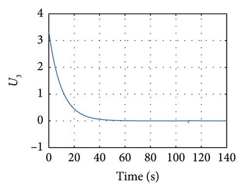
Meanwhile in Figure 10, the control synchronizing input is presented, evincing the control effort of the synchronization approach.
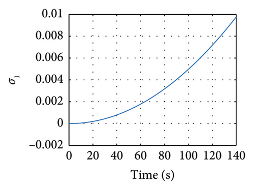
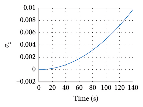
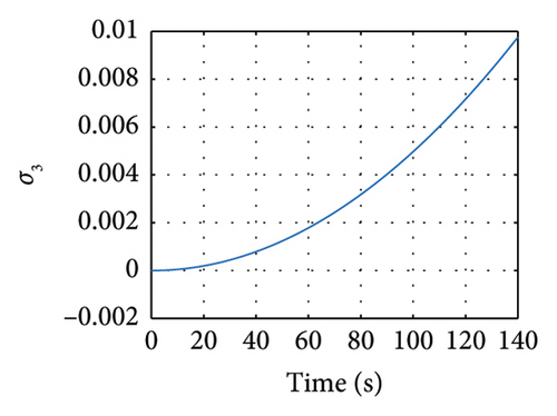
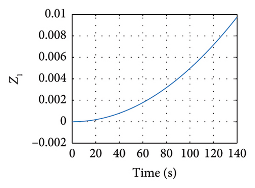
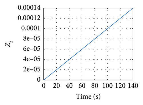
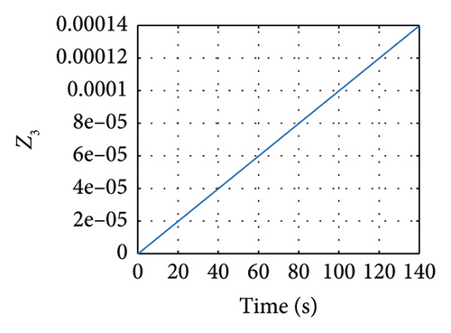
Meanwhile, in Figures 11 and 12, the sliding variables σ and z showing the response of these variables are evinced.
5. Robust Synchronization of the Uncertain Elegant Oscillator
In this section, the synchronization of the uncertain elegant oscillator is achieved. It is important to mention that the kind of uncertainty considered in this research study and in this section are parametric uncertainties. As a future direction, other kinds of uncertainties according to their topology are included in this research study. First, the response chaotic system is considered as an uncertain nonlinear dynamic system, and then by selecting the appropriate robust control Lyapunov function (RCLF), the robust control synchronization law is obtained. For this objective, consider the following corollary without proof [47]:
Corollary 1. Consider the following RCLF and the three class functions α1(.), α2(.), and α3(.). So the control law is obtained if the following are valid:
5.1. Theoretical Framework
Property 1. The parametric uncertainty Δg(Y) is bounded as shown in the following:
Considering the different types of physical systems in which uncertainties are found, such as mechanical, electrical, chemical, and optical, as it is known, the most commonly found uncertainties found in these kinds of systems are basically parametric uncertainties. Despite that this kind of uncertainty is the most simple, they are found in many kinds of physical systems, so the robustness of the open loop nonlinear dynamic system depends on the parameter ϵ. If this parameter is smaller, the effect in the open loop stability is smaller, but if this parameter is high, the open loop stability of the nonlinear chaotic system is significantly affected. Because this elegant oscillator is a newly discovered chaotic system and parametric uncertainties are most commonly found in physical systems, it is not necessary to evince a complete open loop robustness analysis. In the following section is evinced how to obtain the robust control law. The nominal system is given by .
5.2. Robust Synchronizer Design
To obtain a robust control strategy, consider the following theorem.
Theorem 2. Consider the error variables and their first derivative:
Proof 2. Consider the following RCLF:
Obtaining the first derivative of the previous RLCF yields
With the suitable substitution, the previous RCLF first derivative yields
By substituting the control laws, equations (22)–(24) yield
So asymptotical stability is achieved, and the proof is completed.
5.3. Numerical Experiment
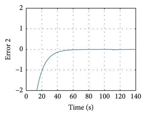
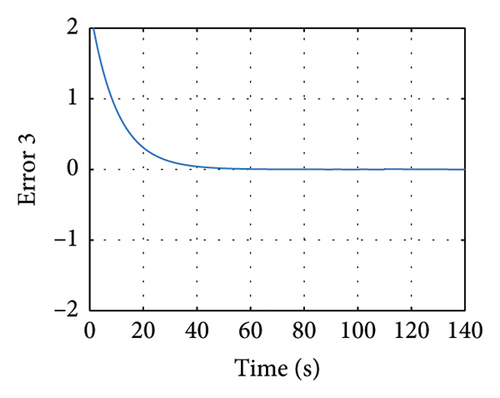
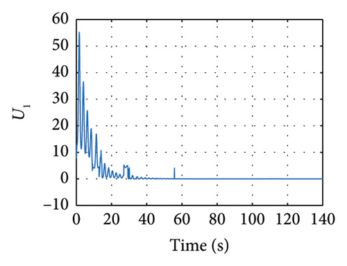
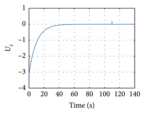
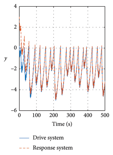
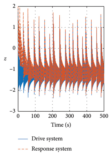
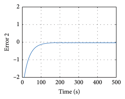
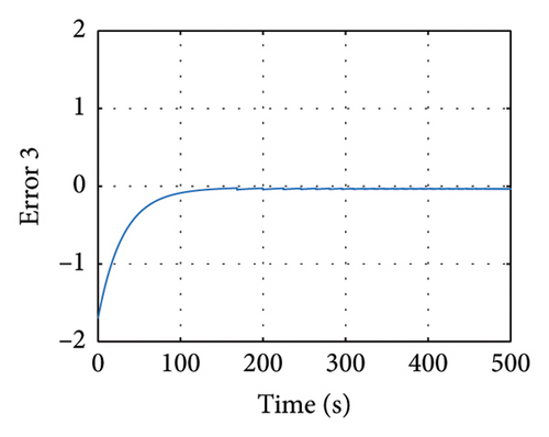
Considering the following gain constants k1 = 30, k2 = 30, and k3 = 30, the simulation was realized by tf = 500 s.
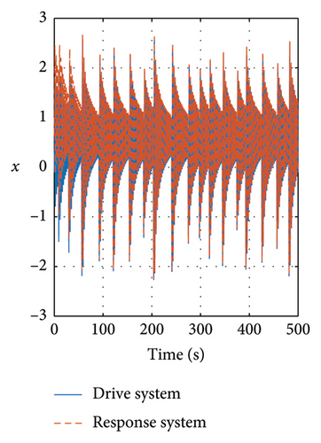
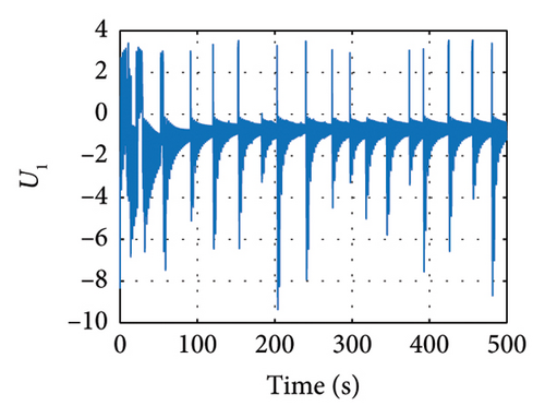
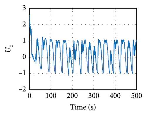
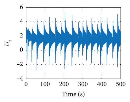
In Figures 13 and 14, the evolution of the state variables of the drive and response systems is shown. It is evinced how these variables are synchronized. In this way, it is achieved efficiently the synchronization by making the trajectory tracking of the response system in comparison with the drive system. Finally in Figure 15, the evolution in time of the input variables is depicted, showing how these variables evolve in time in order to keep an accurate synchronicity between the drive and response system variables until the error reaches the zero value in finite time.

6. Conclusions
Through the introduction of this oscillator, we observe that an elegant oscillator displays distinct and appealing dynamics. Positioned at the intersection of three special classes of oscillators, its location is defined by unique characteristics. Our exploration not only unveils the dynamics but also elucidates the synchronization mechanisms for this oscillator. The results underscore the efficacy of our developed super-twisting sliding mode controller. The forthcoming focus of our research will revolve around the application of this elegant oscillator, opening avenues for further investigation.
Conflicts of Interest
The authors declare no conflicts of interest.
Funding
No funding was received for this research.
Open Research
Data Availability Statement
Data sharing is not applicable to this article as no datasets were generated or analyzed during the current study.


