Chaotic Image Encryption Scheme Based on Improved Z-Order Curve, Modified Josephus Problem, and RNA Operations: An Experimental Li-Fi Approach
Abstract
Image encryption schemes are predominantly software-based. Only a select few have been implemented in real-life communication systems. This paper introduces a novel chaotic image encryption scheme based on a modified Z-order curve, a modified Josephus problem, and an improved Vigenère cipher–based ribonucleic acid (RNA) operation. It is implemented and assessed within a light-fidelity (Li-Fi) infrastructure, comprising two core components: software and hardware. The software component manages data encryption and decryption, while the hardware ensures efficient data transmission. The proposed encryption scheme starts with a pixel-level permutation based on an improved Z-order curve, applicable to rectangular images, optimizing efficiency and increasing permutation ability. This is followed by a bit-level permutation using a modified Josephus problem, which enhances the diversity of generated sequences and introduces additional dislocation effects. Subsequently, a Vigenère cipher–based RNA operation serves for diffusion alongside basic RNA operations and the cipher block chaining (CBC) mode. Theoretical analyses and experimental findings demonstrate that the proposed encryption scheme is highly robust, outperforming several existing cryptosystems. Moreover, owing to its successful implementation, the proposed encryption scheme signifies a compelling stride toward bolstering secure visible light communication systems.
1. Introduction
The rapid advancement of information and communication technologies has markedly enhanced daily conveniences. The Internet facilitates the exchange of a wide array of information, yet the security of exchanged data, particularly when it is confidential, remains paramount [1, 2]. Over recent decades, encryption algorithms such as the data encryption standard (DES) and advanced encryption standard (AES) have emerged to safeguard sensitive data [3, 4]. However, these conventional schemes often prove inadequate in effectively securing images due to their inherent high correlation and data redundancy [5]. Consequently, chaos-based image encryption schemes have been introduced to address these challenges. They can be classified into several categories.
In the first category, schemes leveraging the inherent advantages of low-dimensional chaotic systems and chaotic maps, such as their high sensitivity to system parameters, their simple structure that facilitates implementation, and their high encryption rates, were proposed. For instance, in Reference [6], a medical image encryption scheme based on a one-dimensional chaotic logistic map and the generalized Arnold map was introduced. An encryption scheme based on a chaotic sequence and wavelet transform was proposed in Reference [7]. In Reference [8], an image encryption scheme based on delay-induced hyperchaos, the Arnold map, and a multishift cipher function was proposed. In Reference [9], the authors designed a visualized image encryption scheme based on a two-dimensional logistic-adjusted Chebyshev map. The authors of Reference [10] introduced a color image encryption scheme that considered the properties of color images and Latin squares. In Reference [11], the authors constructed a novel 2D cosine–sine interleaved chaotic map using two separate trigonometric functions, without composite operations. In Reference [12], the authors introduced a 1D chaotic model termed the cosine-coupled chaotic model, based on the absolute value function and the cosine function. The authors of Reference [13] presented an image encryption scheme utilizing a two-dimensional enhanced logistic modular map based on vector-level operations. In Reference [14], the authors presented a multispace confusion image encryption methodology utilizing a 2D Vincent map. This technique significantly bolstered security through the implementation of a two-stage permutation process encompassing both column and row permutations. However, image encryption schemes based on low-dimensional chaotic systems and maps [6, 7] generally exhibit lower security due to their uneven distribution, small chaotic intervals, limited key space, and inadequate randomness. This has led to the cryptanalysis of some encryption schemes [15–17]. For instance, Reference [17] proposed a chosen ciphertext attack method to break a bit-level image encryption algorithm based on chaotic maps.
- •
Proposing an improved Z-order curve-based permutation to address limitations observed with the standard Z-order curve-based approach. The proposed improved Z-order curve is versatile, suitable for square and rectangular images, thereby enhancing efficiency and improving permutation complexity, essential for robust image encryption.
- •
Introducing a modified Josephus problem–based permutation that enhances the granularity required for robust encryption schemes.
- •
Developing a novel RNA operation based on the Vigenère cipher, aiming at reducing computational time, since there is no need to code the key sequence and perform item-to-item operations as usual.
- •
Enhancing unpredictability of the system by synchronizing the chaotic system with the computer’s timestamp using the SHA3-512 hash function.
- •
Designing a robust encryption scheme applicable to all types of images.
- •
Validating the proposed encryption scheme in a real-life communication system.
- •
Achieving superior performance metrics compared to several existing schemes in the literature.
- •
Using a delayed HNN characterized by its infinite-dimensional properties and hyperchaotic dynamics to significantly enhance the robustness of the encryption mechanism.
The remainder of this paper is structured as follows: Section 2 outlines the proposed system and model, while Section 3 covers experimental results, safety analysis, and comparative analysis. Finally, conclusions are presented in Section 4.
2. System and Model
In this section, we introduce and elaborate on the proposed system and model, detailing its architecture, components, and the underlying theoretical framework that distinguishes it from existing methodologies.
2.1. Proposed Li-Fi Infrastructure
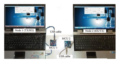
Figure 1 presents two nodes (laptops) in which our Li-Fi application is installed. This Li-Fi application encrypts and decrypts the images using the proposed encryption scheme and further encrypts the key parameters of the proposed encryption scheme using the RSA algorithm to achieve an asymmetric encryption architecture. Each node interfaces with a microcontroller unit (MCU) through a universal serial bus (USB) cable. The MCU drives (i) a light-emitting diode (LED) serving as the emitting antenna for the light signals (ii) and a photodetector (PD) functioning as the receiving antenna for the reverse light signals. Consequently, a Li-Fi modem comprises an LED and a PD integrated within a single MCU. Encrypted data can be bidirectionally transmitted between node 1 and node 2, as indicated by the double arrow.

2.1.1. Transmission Process
Our system is designed to handle image files with pixel values ranging from 0 to 255. Each encrypted pixel is encoded using 8 bits (1 byte). Following encoding, the data are structured into universal asynchronous receiver transmitter (UART) data frames. In the Li-Fi modem, the incoming bit stream undergoes modulation into unipolar on–off keying non-return-to-zero (OOK-NRZ) electrical pulses. OOK-NRZ modulation involves toggling the carrier’s amplitude between two states (0 and 1), aligning with binary data transmission principles [39]. These pulses drive the emitting antenna (LED), where the optical power output correlates directly with the intensity of the forward current [40].
2.1.2. Reception Process
2.2. Encryption Algorithm Foundation
2.2.1. Delayed HNN
2.2.2. SHA3-512
SHA3-512 is a cryptographic hash function designed to irreversibly transform inputs of arbitrary size into a fixed-length output of 512 bits, known as a hash value or digest [46]. Among its notable attributes, SHA3-512 offers enhanced security and longer hash outputs compared to other hash functions. Its irreversibility ensures resilience against plaintext and ciphertext attacks.
2.2.3. Improved Z-Order Curve-Based Permutation
- •
Step 1: Divide the plain 2D array X of size M × N into small blocks Xbi of size Mr × Nc as follows:
(10) -
where i = 1, 2, …, (M × N/Mr × Nc), r = 1, 2, …, Mr, and c = 1, 2, …, Nc. Mr and Nc are determined following Algorithm 1. Then, each block undergoes the following steps.
- •
Step 2: Generate two equal-sized square matrices per block. If the block is square, duplicate it; otherwise, scan bidirectionally along its shorter side to derive two square matrices.
- •
Step 3: Randomly select two complementary transformation modes from one of the three types of Z-order filling curves. Apply them individually to each of the two squared matrices to generate two vectors.
- •
Step 4: Cross-combine the two vectors to form a new vector matching the original block’s size.
- •
Step 5: Reshape the vector to obtain the scrambled block.

-
Algorithm 1: Algorithm used to determine the optimal size of an image block.
-
Input:M, N
-
Output:Mr, Nc
- 1.
fori = 1 to M − 1do
- 2.
Compute a = (M/M − i)
- 3.
Ifis integer(a)then
- 4.
A(i) = a
- 5.
End if
- 6.
End for
- 7.
forj = 1 to N − 1do
- 8.
Compute b = (N/N − j)
- 9.
Ifis integer(b)then
- 10.
B(j) = b
- 11.
End if
- 12.
End for
- 13.
Randomly select two integers Mr from set A and Nc from set B, ensuring that the smaller of the two integers is a power of 2.
Figure 2 illustrates steps 2–5 applied to a block of size 4 × 6.
The results demonstrate that our framework offers enhanced robustness compared to the standard model, as the positions of nearly all elements in the scrambled block have been altered. Additionally, the improved Z-order curve can be applied to nonsquare images, enhancing efficiency and increasing permutation complexity, which is critical for robust image encryption.
2.2.4. Modified Josephus Problem–Based Permutation
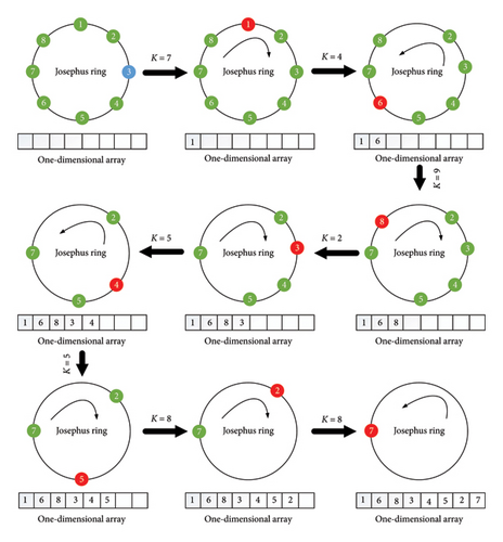
The Josephus problem describes a scenario where N individuals stand in a circle awaiting execution. They are counted in a fixed direction, and K people are skipped while the next is killed until only one person is left [28]. Recently, this problem has found application in pixel-level permutation for image encryption [48]. In the traditional Josephus problem, the step size K is constant, and the scan proceeds either clockwise or counterclockwise. In contrast, the modified Josephus problem proposed in this study introduces variability by randomly altering the starting position, step size, and direction. This approach increases the diversity of generated sequences and introduces an additional dislocation effect, enhancing the effectiveness of the permutation. Figure 3 illustrates this process for N = 8.
2.2.5. Proposed RNA Operation
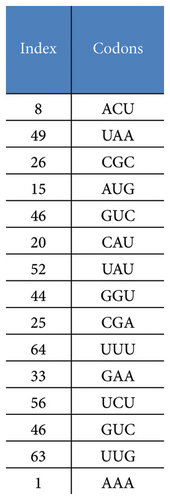
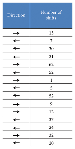
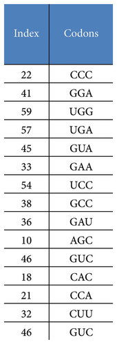
The RNA sequence plays a pivotal role across diverse scientific disciplines, including basic biological research, diagnostics, biotechnology, forensics, biological systematics, and cryptography [20, 49, 50]. An RNA molecule consists of four distinct nucleic acids: adenine (A), cytosine (C), guanine (G), and uracil (U). In the context of protein synthesis, sets of three consecutive bases within the messenger RNA (mRNA) chain encode specific amino acids and are known as genetic codons. Typically, there are 64 unique codons that facilitate the translation of mRNA into proteins [51]. In this paper, leveraging the principle from Vigenère cipher [52], we propose an RNA operation aimed at transforming an input RNA array. Each codon within the array is substituted with another codon selected from a comprehensive set of 64 possibilities to produce an output RNA array (Figure 4). The substitution process involves determining the index of the replacement codon using a transition table generated dynamically by chaotic sequences. This table includes parameters that dictate the number and direction of shifts applied during the substitution process. Notably, this operation is time-efficient since there is no need to code the key sequence and perform item-to-item operations as usual.
2.3. Encryption Scheme
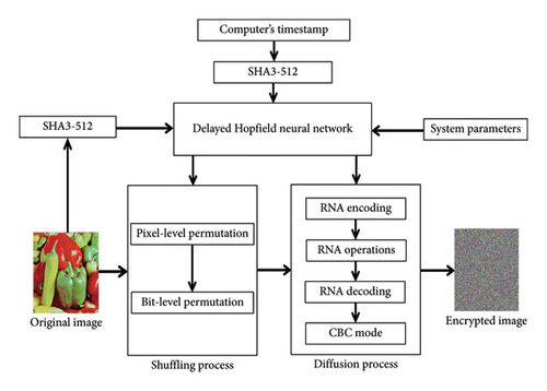
The proposed encryption scheme supports digital images of any size and type (binary, grayscale, color) with pixel values ranging from 0 to 255, encoded across 256 levels. In this subsection, we consider X as a matrix representing a plain image and Y as the matrix of an encrypted image, all of the same size [M, N, O]. The encryption process flowchart is illustrated in Figure 5, and its detailed description follows in the subsequent sub-subsections.
2.3.1. Key’s Parameters and System Initial Values Generation
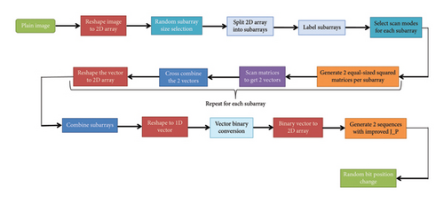
2.3.2. Shuffling Process
- •
Step 1: Obtain the two 512-bit parameters (γ1 and γ2) and the system parameters (aij, bij, cij, Ii, τij(t)).
- •
Step 2: Using γ1 and γ2, calculate the initial values of the delayed HNN following equations (11) and (12).
- •
Step 3: Iterate the delayed HNN for 8 × M × N × O + 1000 times, discarding the initial 1000 values. The resulting elements are then converted into a sequence of integers ranging from 0 to 255. These integers are assigned to a vector Sq as follows:
(13) -
where i = 1, 2, 3, …, 8 × N × M × O.
- •
Step 4: Transform image X into a single 2D array X1 of dimension [M, N × O] as
(14) -
The function “reshape(Q, [H, U])” reshapes Q into a H-by-U matrix.
- •
Step 5: Use the method outlined in 2.2.3 to perform a pixel-level permutation on X1, resulting in the 2D array Xen2; the corresponding transformation modes (Z_mode) are selected as follows:
(15) -
Z_mode values range from 1 to 8 for the Lebesgue curve, from 9 to 16 for the first quasi-Lebesgue curve, and from 17 to 24 for the second quasi-Lebesgue curve.
- •
Step 6: Transform Xen2 into a one-dimensional row vector and convert each of its elements into bits using
(16) -
The function “dec2base” converts a decimal number to a character vector representing a base 2 number.
- •
Step 7: Reshape Xen2b into a 2D array Cq as
(17) -
with NP1 = 8 × M and NP2 = N × O.
- •
Step 8: Use the modified Josephus problem (denoted as J_P) proposed in 2.2.4 to generate two sequences as follows:
(18) -
where the start positions (start_pos1, 2), steps size (step_size1, 2(i)), and directions (dir1, 2(i)) are given as
(19)(20)(21) - •
Step 9: Finally, each bit’s position in Cq undergoes random modification to yield Xen3 as follows:
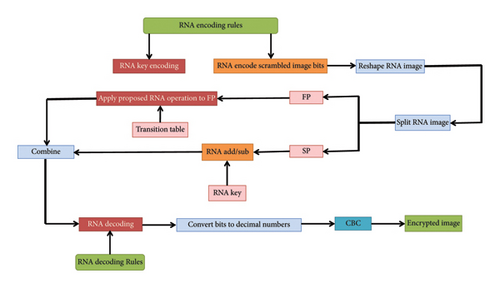
2.3.3. Diffusion Process
- •
Step 1: The chaotic sequence Sq is first converted into a sequence of bits, which are then concatenated to form a one-dimensional binary vector.
- •
Step 2: The encryption and decryption rules (Enc_rule(i)), (Dec_rule(i)) are, respectively,
(23) -
Then, following the specified encoding rules Enc_rule(i) as described in equation (23), dynamic RNA encoding operations are applied to the vector Xen3 and Sq, resulting in the vectors Xen3RNA and SqRNA:
(24) -
where i = 1, 2, 3, …, M × N × O and k = 1, 3, 5, …, M × N × O.
- •
Step 3: Reshape the vector Xen3RNA into an L × 4 matrix as follows:
(25) -
with L = M × N × O/4.
- •
Step 4: Split Xen4RNA into two parts FP and SP as
(26) - •
Step 5: Depending on whether y1(i) ≤ y2(i), perform RNA addition or subtraction operation between the samples of SP(i) and SqRNA(i) to generate SPRNA(i);
- •
Step 6: The proposed Vigenère cipher–based RNA operation described in 2.2.5 is employed on the vector FP to derive FPRNA. The parameters governing this operation, including the number of shifts (CV) and their direction (Dr), are dynamically generated using chaotic sequences as specified in the following equation.
(27) - •
Step 7: Concatenate SPRNA with FPRNA horizontally and transform the result into a one-dimensional vector Xen5RNA.
- •
Step 8: Decode Xen5RNA according to the rule specified in sequence Dec_rule(i) to obtain Xen5,
(28) -
and concatenate it into a one-dimensional binary vector before converting it into decimal representation as
(29) -
with k = 1, 9, 17, …, M × N × O/8, i = 1, 2, 3, …, M × N × O, and base2dec, a function which converts text representing a number in base 2, into its decimal equivalent.
- •
Step 9: The CBC mode is applied to Xen6 to obtain Xen7 as follows:
(30) -
where Xen7(1) = index(max(Sq(1 : 255))) is the initialization vector of the CBC mode.
- •
Step 10: The final encrypted image is given as follows:
3. Experimental Results and Comparative Analysis
This section presents and analyzes the results obtained by our innovative encryption method. These results are compared with existing techniques in the literature to demonstrate their advantages in terms of security, robustness, and efficiency.
3.1. Experimental Results
This subsection presents the experimental results and performance analysis of the proposed encryption scheme. A robust image encryption scheme must withstand various attacks to ensure the security of images during transmission. We evaluate the performance of our encryption scheme using 15 metrics on binary images (binary, QR code), grayscale images (boat, cameraman, male), and color images (airplane, couple, peppers, female, house). The performance analysis of the proposed encryption scheme is conducted within the context of a Li-Fi infrastructure, where the plain images are the transmitted images and the decrypted images are those received at the destination node (Figure 1).
3.1.1. Key Space Analysis
The key space of an encryption scheme is a fundamental metric that determines its resilience to brute-force attacks, calculated based on the total possible combinations of all key parameters [20, 26]. In our proposed encryption scheme, the key space is shaped by the initial values and system parameters of the delayed HNN. Additionally, our computational environment operates with a numerical precision of 10−16. Specifically, we use two initial values for the HNN, each with an accuracy of 10−16, leading to 1016 possible values per parameter and a total of 1032 combinations. Additionally, the HNN comprises of 20 system parameters, each with the same accuracy of 10−16, contributing 10320 possible combinations. As a result, the overall key space is 1032 × 10320 = 10352 ≈ 21166, which is vastly larger than the recommended threshold for secure encryption schemes. For comparison, modern cryptographic standards suggest a key space of at least 2128 (approximately 1038.5) to guard against brute-force attacks [53]. With a total key space of 10352, our scheme provides a high level of security, offering robust resistance to exhaustive search attacks. Given that the key space may fluctuate depending on the computational environment, it is crucial to carefully select the implementation platforms to optimize the key space. This ensures maximization of cryptographic robustness and significantly enhances the security of the algorithms against brute-force attacks.
3.1.2. Encryption Effect
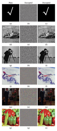
Figure 8 presents the plain, encrypted, and decrypted images for various image types (binary, boat, cameraman, airplane, couple, peppers). The encrypted images (Figure 8(b, e, h, k, n, q)) are completely unrecognizable, demonstrating the effectiveness of the encryption process. Furthermore, the decrypted images (Figure 8(c, f, i, l, o, r)) closely match their corresponding plain images (Figure 8(a, d, g, j, m, p)), indicating the high accuracy and reliability of the decryption process. These results highlight the robustness of the proposed scheme in effectively encrypting and decrypting various types of images.
3.1.3. Statistical Analysis
Statistical analysis is a critical test to assess the robustness of an encryption scheme. This analysis encompasses several parameters, including (1) the entropy of images, (2) the correlation coefficients of adjacent pixels, (3) the histogram of images, (4) the chi-square test, and (5) the deviation of the histogram of the encrypted images from the ideal uniform histogram.
3.1.3.1. Entropy Analysis
| Images | Original images | Encrypted images |
|---|---|---|
| Binary | 0.3926 | 7.9993 |
| QR code | 1.9437 | 7.9992 |
| Boat | 7.1914 | 7.9993 |
| Cameraman | 7.0097 | 7.9968 |
| Male | 7.5237 | 7.9998 |
| Airplane | 6.6639 | 7.9998 |
| Couple | 6.2945 | 7.9992 |
| Peppers | 7.6698 | 7.9998 |
| Female | 6.8981 | 7.9990 |
| House | 7.0686 | 7.9990 |
3.1.3.2. Pixels Correlation Coefficients Analysis
| Images | Plain images | Encrypted images | |||||
|---|---|---|---|---|---|---|---|
| H | V | D | H | V | D | ||
| Binary | 0.9798 | 0.9830 | 0.9424 | −0.0029 | 0.0132 | −0.0071 | |
| QR code | 0.9710 | 0.9693 | 0.9349 | −0.0179 | −0.0023 | −0.0107 | |
| Boat | 0.9478 | 0.9706 | 0.9272 | −0.0178 | −0.0051 | 0.0015 | |
| Cameraman | 0.9299 | 0.9595 | 0.9055 | −0.0066 | −0.0069 | −0.0116 | |
| Male | 0.9777 | 0.9813 | 0.9739 | −0.032 | −0.016 | −0.0091 | |
| Airplane | R | 0.9739 | 0.9488 | 0.9337 | 0.0219 | −0.0032 | 0.0243 |
| G | 0.9614 | 0.9689 | 0.9419 | 0.0163 | 0.0007 | −0.0111 | |
| B | 0.9096 | 0.9418 | 0.8717 | −0.0083 | 0.0312 | 0.0095 | |
| Couple | R | 0.9492 | 0.9638 | 0.9193 | 0.0033 | 0.0063 | 0.0056 |
| G | 0.9193 | 0.9496 | 0.9007 | −0.0196 | −0.0149 | 0.0080 | |
| B | 0.9096 | 0.9418 | 0.8717 | −0.0083 | −0.0142 | 0.0191 | |
| Peppers | R | 0.9592 | 0.9690 | 0.9551 | 0.0311 | −0.0119 | 0.0159 |
| G | 0.9820 | 0.9801 | 0.9666 | 0.0041 | −0.0140 | −0.0096 | |
| B | 0.9701 | 0.9693 | 0.9364 | −0.0151 | −0.0069 | −0.0314 | |
| Female | R | 0.9751 | 0.9642 | 0.9667 | −0.0350 | 0.0049 | −0.0037 |
| G | 0.9692 | 0.9618 | 0.9528 | 0.0056 | −0.0122 | −0.0067 | |
| B | 0.9618 | 0.9516 | 0.9392 | 0.0472 | −0.0178 | −0.0017 | |
| House | R | 0.9695 | 0.9397 | 0.9020 | 0.0061 | 0.0099 | −0.0281 |
| G | 0.9814 | 0.9482 | 0.9370 | −0.0175 | −0.0313 | 0.0142 | |
| B | 0.9819 | 0.9774 | 0.9653 | 0.0006 | −0.0219 | 0.0162 | |
From Table 2, it is evident that the correlation coefficients of adjacent pixels in the encrypted images are significantly reduced, indicating the high security level of the proposed encryption scheme. Figures 9 and 10 depict the correlation distribution diagrams of adjacent pixels in the horizontal (H), vertical (V), and diagonal (D) directions for two example images: “cameraman” and “airplane.”
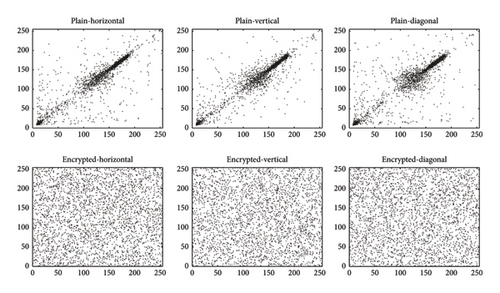
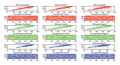
One can observe that the correlation distribution diagrams of adjacent pixels in plain images show high correlation, whereas those of encrypted images exhibit uniform and irrelevant correlation. This observation highlights our scheme’s effectiveness in minimizing correlations between adjacent pixels, thereby achieving robust encryption.
3.1.3.3. Histogram Analysis
One can evaluate an image encryption scheme by plotting the distribution of pixel values in images before and after encryption; this is referred to as an image histogram [54]. Figures 11 and 12 show the histograms of some plain and encrypted grayscale (cameraman) and color (airplane) images.
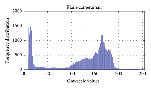
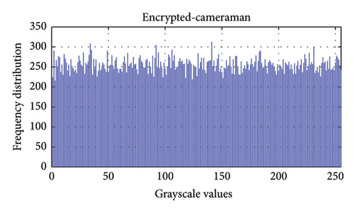
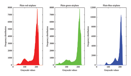
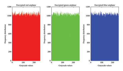
Table 3 presents the chi-square values of encrypted images. A histogram’s flatness is typically confirmed if its chi-square value is less than 293.2478 [25]. Furthermore, the deviation of the encrypted histogram from the ideal histogram serves to evaluate resistance against statistical attacks. From Table 3, it is evident that all deviations are minimal, affirming that the proposed encryption scheme closely approximates the ideal standard.
| Images | Chi-square values | Deviations | |
|---|---|---|---|
| Binary | 248.15 | 0.025 | |
| QR code | 272.77 | 0.025 | |
| Boat | 252.39 | 0.024 | |
| Cameraman | 291.5078 | 0.053 | |
| Male | 252.62 | 0.012 | |
| Airplane | R | 243 | 0.048 |
| G | 272.32 | 0.050 | |
| B | 253.26 | 0.051 | |
| Couple | R | 200.20 | 0.044 |
| G | 283.66 | 0.052 | |
| B | 247.89 | 0.049 | |
| Peppers | R | 251.19 | 0.024 |
| G | 267.21 | 0.025 | |
| B | 258.93 | 0.024 | |
| Female | R | 281.17 | 0.051 |
| G | 279.03 | 0.054 | |
| B | 274.80 | 0.051 | |
| House | R | 286.78 | 0.051 |
| G | 272.88 | 0.052 | |
| B | 285.15 | 0.053 | |
3.1.4. Differential Attack
In equations (37) and (38), Y1i and Y2i denote the pixel values of the two encrypted images and N represents the total number of pixels. According to the literature, the minimum expected values for NPCR and UACI are 99.6094%, and 33.4635%, respectively [56]. In our evaluation, we conducted tests by randomly altering a single pixel in the plain image. The results are summarized in Table 4.
| Images | NPCR (%) | UACI (%) |
|---|---|---|
| Binary | 99.6284 | 33.5432 |
| QR code | 99.6240 | 33.5055 |
| Boat | 99.6298 | 33.4380 |
| Cameraman | 99.6231 | 33.5393 |
| Airplane | 99.6226 | 33.4650 |
| Couple | 99.6592 | 33.4613 |
| Peppers | 99.6109 | 33.4527 |
| Female | 99.6134 | 33.5324 |
| House | 99.6129 | 33.5483 |
Table 4 demonstrates that the proposed encryption scheme successfully meets the NPCR and UACI criteria across various images, indicating its robustness against differential attacks.
3.1.5. Peak Signal-to-Noise Ratio
| Images | PSNR (dB) |
|---|---|
| Binary | 4.7582 |
| QR code | 4.9803 |
| Boat | 9.2952 |
| Cameraman | 8.3579 |
| Male | 8.003 |
| Airplane | 7.9710 |
| Couple | 6.2761 |
| Peppers | 8.0679 |
| Female | 7.2854 |
| House | 8.9204 |
3.1.6. Occlusion Attacks Analysis
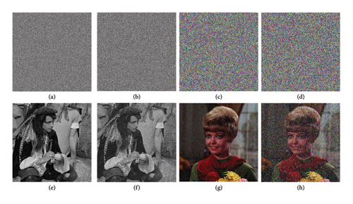
Occlusion attacks analysis is crucial for assessing the robustness of an encryption scheme. Occlusion attacks occur when parts of the encrypted image are lost during transmission [57]. A reliable encryption scheme must effectively mitigate such vulnerabilities. Figure 13 presents the experimental results of the proposed scheme under occlusion attacks. Despite losses of approximately 16.66% (Figures 13(a) and 13(c)) and 33.33% (Figures 13(b) and 13(d)) of encrypted images, the corresponding decrypted images (Figures 13(e), 13(f), 13(g), and 13(h)) remain identifiable. This demonstrates the scheme’s resilience against occlusion attacks.

3.1.7. Noise Attacks Analysis
Another crucial metric for evaluating an encryption scheme is its resistance against noise attacks [58]. To assess this, an amount of salt-and-pepper noise was added to some encrypted images. Figure 14 demonstrates that our scheme successfully reconstructs readable images from the corrupted encrypted ones.
3.1.8. Key Sensitivity Analysis
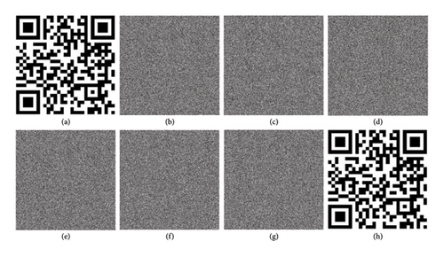
Sensitive key parameters are crucial for the effectiveness of an encryption scheme during both encryption and decryption processes [56, 59, 60]. Key sensitivity serves as a fundamental metric for assessing the reliability of a cryptographic system. To evaluate the sensitivity of the keys employed in our proposed scheme, we defined three secret keys (K1, K2, K3), where K2 and K3 were derived from K1 with a minute variation affecting one key parameter by a magnitude of 10−16, outlined as follows: K1(a11 = 2, a12 = −0.1, a21 = −5, a22 = 3), K2(a11 = 2, a12 = −0.1, a21 = −5, a22 = 3 + 10−16), and K3(a11 = 2, a12 = −0.1, a21 = −5, a22 = 3 + 2 × 10⁻¹⁶).
Figure 15 illustrates the outcomes of key sensitivity experiments conducted during the encryption and decryption processes. It is evident that when using secret keys K2 and K3 for decryption, which differ slightly from the encryption key K1, the resulting decrypted images are rendered unintelligible (Figures 15(f) and 15(g)). However, when employing the correct key K1, the decrypted image closely resembles the original plain image (Figure 15(h)). Table 6 reveals a significant mean square error (MSE) between the encrypted images, despite the similarity of the keys used. This observation holds true for the decrypted images as well. Therefore, these findings underscore the sensitivity of the secret keys in our proposed scheme during both the encryption and decryption processes.
| Data 1 | Data 2 | MSE between data 1 and data 2 |
|---|---|---|
| E1 = (P, K1) | E2 = (P, K2) | 1.0918 × 10⁴ |
| E1 = (P, K1) | E3 = (P, K3) | 1.0918 × 10⁴ |
| E2 = (P, K2) | E3 = (P, K3) | 1.0903 × 10⁴ |
| D1 = (E1, K3) | D2 = (E1, K2) | 2.0637 × 10⁴ |
| D2 = (E1, K2) | D3 = (E1, K1) | 2.0681 × 10⁴ |
| D1 = (E1, K3) | D3 = (E1, K1) | 1.0893 × 10⁴ |
| P | D3 = (E1, K1) | 0 |
3.1.9. Time Complexity
The time complexity of an encryption scheme is critical, especially in real-time communication applications [61, 62]. The proposed image encryption scheme exhibits linear complexity, specifically O(m × n × o), where [m, n, o] denote the dimensions of the input image file. That confirms the suitability of our algorithm for real-time communication applications executed on computer systems.
3.1.10. Speed for the Encryption Process
To measure the speed of our encryption scheme, we used images of different sizes with hardware configuration 3.4 GHz, Intel(R)Core(TM) i76600U, 16 GB RAM, Windows 10, and MATLAB 2018. Table 7 reports the findings. The encryption time is notably substantial, resulting in diminished throughput, likely attributable to the implementation of the encryption algorithm in MATLAB. To mitigate this issue, it would be advantageous to employ compiled languages such as C++, which could significantly enhance computational efficiency and improve throughput.
| Images | Size | Time (s) | Throughput (Mbps) |
|---|---|---|---|
| Binary | 500 × 500 | 5.021 | 0.398 |
| QR code | 500 × 500 | 5.250 | 0.381 |
| Boat | 512 × 512 | 5.523 | 0.379 |
| Cameraman | 256 × 256 | 1.580 | 0.332 |
| Male | 1024 × 1024 | 22.825 | 0.367 |
| Airplane | 512 × 512 × 3 | 17.122 | 0.367 |
| Couple | 256 × 256 × 3 | 4.334 | 0.362 |
| Peppers | 512 × 512 × 3 | 17.036 | 0.369 |
| Female | 256 × 256 × 3 | 4.10091 | 0.383 |
| House | 256 × 256 × 3 | 4.523 | 0.347 |
3.1.11. Checksum Using SHA-256
Ensuring data integrity is crucial across various applications, necessitating robust and fully reversible encryption schemes. Checksums, typically computed using cryptographic hash functions, verify the integrity of received data. In our evaluation, we employ the SHA-256 hash function to compare hash values of received images with their transmitted counterparts [59]. Table 8 shows identical hash values for transmitted and received images, confirming lossless transmission and decryption processes. These results underscore the complete reversibility and high reliability of both the proposed encryption scheme and the Li-Fi infrastructure.
| Images | Hash values of transmitted images | Hash values of received images |
|---|---|---|
| Binary | 8cc371c3d3118a192f26a24a8bd21db8eb831814f91820c5b25e169056988006 | 8cc371c3d3118a192f26a24a8bd21db8eb831814f91820c5b25e169056988006 |
| Airplane | ae9eba12b80df955e47585bf4a16332ea0dadc753668d3457c509564934dbd40 | ae9eba12b80df955e47585bf4a16332ea0dadc753668d3457c509564934dbd40 |
3.1.12. Known Plaintext and Chosen Plaintext Attacks
The principal aim of cryptanalysis is to recover the secret key or its components in order to decrypt ciphertexts produced by a cryptographic system. The literature delineates four primary attack scenarios: ciphertext-only attack, known plaintext attack, chosen plaintext attack, and chosen ciphertext attack. Among these, known plaintext and chosen plaintext attacks are particularly powerful and require careful consideration. To crack a cryptographic scheme, two scenarios may be considered: (1) cracking the secret key parameters of the system which is often impossible and (2) cracking the encryption sequence which is more feasible depending on the type of cryptographic scheme used. Often two different types of cryptographic schemes may be considered: the first is the open-loop scheme, in which the secret key parameters are independent from the plaintext, and the second is close-loop scheme, in which the parameters are linked to the plaintext. In the open-loop schemes, the encryption sequence is the same for different encryption schemes therefore making it easy to recover it through chosen plaintext attack; while, the close-loop system is a one-tap system in which each plaintext is encrypted with a different sequence. Our encryption algorithm is robust to known plaintext and chosen plaintext attacks for the following reasons: (1) It is a close-loop scheme in which the secret keys are intricately linked to both the input image and the computer’s timestamp via the SHA3-512 hash function. Therefore, any given plain image (even one chosen by the attacker) is encrypted by a different encryption sequence making it difficult to obtain the encryption sequence. Moreover, repeated encryption of the same plain image is done with different encryption keys due to the use of the computer’s timestamp which further improves the difficulty to obtain the encryption sequence. (2) It uses the CBC mode which makes it difficult to predict the encryption sequence. Indeed, a random IV is used in the diffusion of the first block in the CBC mode. This therefore makes it harder for the attackers to establish a meaningful relationship between the plaintexts and ciphertexts. Besides, the random IV serves as salt in the confused image and contributes to destroy predictable patterns in it. The destruction of predictable patterns increases as the chaining evolves in such a way that the obtained ciphertext cannot easily be linked to the plaintext.
3.2. Comparative Analysis
Numerous image encryption schemes have been proposed in the literature. To showcase the contribution of our scheme, we compare its experimental results with those of existing schemes. Table 9 presents the outcomes of this comparative analysis, focusing on metrics such as information entropy, correlation coefficients of encrypted images, NPCR, UACI, key space, and experimental realization.
| References | Entropy | Correlation coefficients | NPCR | UACI | Key space | Throughput (Mbps) | Experimental realization | ||
|---|---|---|---|---|---|---|---|---|---|
| H | V | D | |||||||
| [6] | — | 0.0361 | −0.0408 | −0.0088 | 99.64 | 33.54 | k | 5.66 | No |
| [8] | 7.9998 | 0.00075 | 0.0078 | −0.0063 | 99.6102 | 33.4695 | 2256 | 2.27 | No |
| [9] | 7.9965 | 0.0023 | −0.0020 | −0.0073 | 99.6141 | 33.4977 | 1098 | 31.45 | No |
| [10] | 7.9994 | 0.0020 | −0.0009 | −0.0031 | 99.6644 | 33.4670 | 10128 | — | No |
| [13] | 7.9994 | −0.0024 | 0.0007 | 0.0018 | 99.6095 | 33.4633 | 2205 | 22.90 | No |
| [19] | 7.9998 | 0.00007 | 0.00007 | −0.00014 | 99.6127 | 33.4862 | 2213 | — | No |
| [21] | 7.9998 | −0.0025 | 0.0013 | 0.0009 | 99.6084 | 33.4659 | 2541 | 168.56 | No |
| [25] | 7.9998 | 0.0206 | 0.0003 | −0.0141 | 99.6150 | 33.5106 | 10128 | 248.08 | No |
| [30] | 7.9994 | −0.0026 | −0.0012 | −0.0011 | 99.62 | 33.50 | 0.09 × 21080 | — | No |
| [31] | 7.9993 | −0.0014 | −0.0008 | −0.0038 | 99.6095 | 33.4640 | 2260 | 2.30 | No |
| [35] | 7.9997 | −0.0013 | 0.0080 | −0.00113 | 99.59161 | 33.3834 | 2320 | — | Yes |
| [36] | 7.9993 | 0.0007 | 0.0011 | 0.0012 | 99.6112 | 33.3747 | — | — | Yes |
| [37] | 7.9993 | — | — | — | 99.6120 | — | — | — | Yes |
| [63] | 7.9981 | 0.0005 | −0.0032 | −0.0032 | 99.59138 | 33.3861 | 10160 | — | No |
| This work | 7.9998 | −0.03 | −0.016 | −0.0091 | 99.6592 | 33.5483 | 10352 ≈ 21166 | 0.3685 | Yes |
- Note: The bold fonts mean the best results.
In terms of information entropy, our proposed scheme achieves results comparable to those reported in [8, 19, 21, 25], while notably surpassing other references, indicating a high degree of randomness. Moreover, our system exhibits the lowest correlation coefficients among recent advancements in encrypted image correlations. Regarding NPCR and UACI, our scheme outperforms several recent achievements, although the NPCR value reported in Reference [10] slightly exceed ours. Notably, our scheme boasts a larger key space and higher key sensitivity compared to findings in the literature. While our algorithm exhibits linear time complexity, its throughput is currently lower than that reported in the literature. We attribute this discrepancy to the use of MATLAB, an interpreted language. We anticipate that transitioning to a compiled language, such as C++, would substantially enhance execution speed and improve overall throughput. Furthermore, our scheme demonstrates greater resilience against occlusion attacks compared to References [25, 59], where encrypted image segments lost during transmission were not recoverable after decryption, and compared to References [8, 20], where even slight losses resulted in significant degradation of recovered images. Apart from Reference [35], which explores chaos generators on Raspberry Pis for MQTT-based IoT, Reference [36], which details an optimized bit insertion method on a Nios II system, and Reference [37], which employs chaotic binary sequences with artificial neurons for IoT, numerous prior studies are confined to theoretical analyses and simulations. In contrast, our encryption scheme has been empirically validated through its implementation in a Li-Fi infrastructure, thereby demonstrating its efficacy in securing image transmissions over VLC channels.
4. Conclusion
This paper introduced a novel chaotic image encryption scheme based on an improved Z-order curve, a modified Josephus problem, and a Vigenère cipher–based RNA operation. This proposed scheme enhances the efficiency and robustness of traditional encryption schemes and solves the lack of empirical validation. The proposed encryption scheme achieves pixel-level and bit-level permutations of plain images using the improved Z-order curve and the modified Josephus problem, respectively. The diffusion process incorporates a Vigenère cipher–based RNA operation alongside basic RNA operations. The findings demonstrate that the improved Z-order curve-based permutation is suitable for both square and nonsquare images, thereby enhancing efficiency and increasing permutation complexity, which are essential for robust image encryption. Additionally, the modified Josephus problem–based permutation improves the granularity required for secure encryption schemes. Furthermore, the streamlined Vigenère cipher–based RNA operation optimizes the diffusion process for greater computational efficiency. The synchronization of the chaotic system with the plain image and the computer’s timestamp, utilizing the SHA3-512 hash function, significantly enhances unpredictability. Performance analysis conducted in a Li-Fi infrastructure demonstrated the scheme’s effectiveness, security, robustness, and practicality. Future research could focus on (1) optimizing the scheme with higher complex dynamical systems [64–66] or its implementation using compiled languages like C++ for real-time applications and (2) exploring its adaptability across various scenarios and environments.
Conflicts of Interest
The authors declare no conflicts of interest.
Funding
This research did not receive any specific grant from funding agencies in the public, commercial, or not-for-profit sectors.
Open Research
Data Availability Statement
The data supporting the findings of this study are available from the corresponding author upon reasonable request.


