Volume 2025, Issue 1 7157902
Research Article
Open Access

Bifurcation, Chaotic, Sensitivity Analysis, and Optical Soliton Profiles for the Spin Hirota–Maxwell–Bloch Equation in an Erbium-Doped Fiber

Asma Taskeen

Asma Taskeen

Department of Mathematics and Statistics , The University of Lahore , Lahore , Punjab , Pakistan , uol.edu.pk

Search for more papers by this author
Muhammad Ozair Ahmed

Muhammad Ozair Ahmed

Department of Mathematics and Statistics , The University of Lahore , Lahore , Punjab , Pakistan , uol.edu.pk

Search for more papers by this author
Muhammad Zafarullah Baber

Muhammad Zafarullah Baber

Department of Mathematics and Statistics , The University of Lahore , Sargodha Campus, Lahore , Punjab , Pakistan , uol.edu.pk

Search for more papers by this author
Baboucarr Ceesay

Corresponding Author

Baboucarr Ceesay

Mathematics Unit , The University of The Gambia , Serekunda , Western , Gambia , utg.edu.gm

Search for more papers by this author
Nauman Ahmed

Nauman Ahmed

Department of Mathematics and Statistics , The University of Lahore , Lahore , Punjab , Pakistan , uol.edu.pk

Search for more papers by this author
First published: 12 July 2025
Academic Editor: Zine El Abiddine Fellah

Abstract

In this work, the reduced spin Hirota–Maxwell–Bloch (rsHMB) equation is examined analytically. This model is useful for characterizing the propagation of femtosecond pulses in an erbium-doped fiber. The optical soliton solutions of the introduced rsHMB problem are constructed using the Jacobi elliptic function (JEF) expansion technique. This is efficient technique for the exact solitary wave solution of nonlinear partial differential equations (NLPDEs). The multiple soliton profiles are observed in the single and combined wave solutions, such as, bright soliton, dark soliton, singular soliton, kink soliton, and mixed solitons. All of the recently produced soliton solutions are verified by returning them to the relevant system using Wolfram Mathematica soft computation. Additionally, the analysis of bifurcation is investigated and the problem is transformed into a planer dynamical system utilizing a specific transformation. Additionally, by adding definite periodic pressures to the model under consideration, the quasiperiodic solution for the perturbed system is examined numerically. Two-dimensional and three-dimensional phase portraits are plotted in relation to the perturbed models parameter.

1. Introduction

In recent decades, physical problems have been numerically represented by nonlinear partial differential equations (NLPDEs) in physics, biology, plasma, mechanics, hydrodynamics, optics, and many other fields [14]. Since 18th century, numerous scholars have endeavored to translate intricate complicated processes into NLPDEs [5, 6]. It is widely accepted that because of their long-range, accurate data transfer, and enormous capacity, optical solitons are important in the field communication systems. Due to dispersion or spatial diffraction, light packets tend to diffuse as they pass through a medium in optics. A combination of pulse dispersion and refraction nonlinearity produces temporal solitons, while beam diffraction and nonlinearity combine to produce spatial solitons. These two types of optical solitons can be distinguished from one another. Vertical beams that are self-trapped have finite spatial cross sections, known as optical spatial solitons, spread without the divergence that comes with diffused beams. In nonlinear optics, solitons which have the ability to travel over great distances while maintaining their profiles have been investigated both theoretically and practically. The nonlinear Schrödinger (NLS) equation which preserve their polarization states in the nonlinear medium, has given rise to optical solitons.

The NLS models have been the subject of much research lately due to its broad applicability in the description of several nonlinear physical systems. Yesmakhanova et al. [7] examined the (2 + 1)-dimensional Hirota–Maxwell–Bloch system (HMBS), which often controls the transmission of ultrashort pulses in erbium-doped fibers due to higher order effects. Myrzakulov et al. [8] worked on the primary chiral model which includes the HMBS. Myrzakulov et al. [9] investigated the analogous NLS family of equations and related Lax pairings were inferred, including the NLS–HMB equations in (2 + 1) dimensions. Wang et al. [10] illustrated a modified NSL equation with many higher order nonlinear effects can produce first order breather and higher order rogue waves, which mimic femtosecond pulse propagation via nonlinear silica fiber. Zhunussova et al. [11] introduced the self-consistent potentials and integrable reduced form of Heisenberg ferromagnet equations. Xue et al. [12] used the generalized inhomogeneous coupled HMBS, to explored the 1 and 2–soliton solutions were achieved using the Darboux transformation and symbolic computation. Adsuara et al. [13] explored the numerical solutions, which increases the need for effective, highly parallel techniques to address their algorithmic resolution. Sakamoto et al. [14] explored the stabilizing solution of the Hamilton–Jacobi problem can be approximated using two different approaches, stable manifold theory, symplectic geometry, and a Hamiltonian perturbation methodology. Nucci and Leach [15] by using Jacobis approach on the same two equations as Ibragimov, they demonstrate its elegance and simplicity. They demonstrate that Ibragimov’s Lagrangians are specific instances of some of the numerous Lagrangians that can be produced using Jacobi’s approach [15].

Harun-Or-Roshid et al. [16] worked on the dynamical analysis of the of Heisenberg ferromagnetic spin chains mode. Djaouti et al. [17] worked on the bifurcation analysis and solitary wave solution of fractional longitudinal wave equation using the modified simple equation method. Islam et al. [18] investigated the spin solitonic dynamics of the Heisenberg ferromagnetic spin chains model using the unified and simple equation schemes. Chakrabarty et al. [19] used the enhanced modified simple equation to solved the telegraph model with the traveling wave coefficient. Mofarreh et al. [20] solved the fractional order Fokker–Planck equation analytically or numerically to examine the dynamical behavior of the system. Pervin et al. [21] explored the dynamical structures of wave front to the fractional generalized equal width-burgers model. But in this study we use the Jacobi elliptic function (JEF) method to explored the optical solitons for the reduced spin Hirota–Maxwell–Bloch (rsHMB) system.

In this study, we considered an integrable rsHMB system in the following form,
()
where, the complex function M differentiable with respect to time t and spatial variable x to describe how femtosecond pulses are transmitted in an erbium-doped fiber. The real constants are ω and δ, and the modulated waves complex envelope, the real differentiable function N, reflects the degree of inversion of population. |M| represent modulus of M, and the subscripts are the partial derivatives.

Determining the exact solutions for NLS equation is essential since it covers a broad spectrum of phenomena in nonlinear phenomena, engineering, science, and optical fiber. Many mathematicians and researchers have developed efficient methods for find the exact behavior of NLPDEs, such as the extended Tanh–Coth method [22], the modified exp-function method [23], the extended JEF method [24], the generalized Kudryashov method [25] and new extended direct algebraic method [26], extended hyperbolic function method [27] and many others.

Comprehensive numerical simulations are indispensable for ensuring that the derived analytical solutions are correct and have genuine physical meaning. Models based on simplified equations may be quite stable when their underlying assumptions hold but can show increased sensitivity as complications arise in the dynamics. Numerical simulations based on methods like the split-step Fourier approach enable the investigation of how the solutions change with time. Performing such a comparison enables testing whether the derived solitons remain stable, robust, and persistent even when initially and/or along the edges of the system resemble those encountered in practical scenarios. Numerical simulations however, can uncover effects, such as modulational instability, waveform distortion, or energy redistribution that aren’t clearly observable in analytical expressions. Performing numerical simulations in conjunction with the above visual comparisons will greatly improve the reliability of the analytical solutions and add strength to the overall rigor and completeness of the study.

The use of the Jacobi elliptic function expansion (JEFE) method for studying the spin HMBS is considered appropriate since this approach allows the straightforward formulation of periodic and solitary waves for a wide range of nonlinear equations. It provides a systematic and efficient method for obtaining exact analytical solutions that accurately represent the nonlinear wave behaviors characteristic of integrable systems, such as the HMB. The JEFE method stands out as a much simpler and broader alternative to methods like the inverse scattering transform (IST) that require stringent requirements of integrability and can sometimes be challenging to implement. This method also facilitates the generation of solutions for cases characterized by diverse parameter settings, providing a more precise description of different phenomena. A thorough analysis shows that the JEFE method greatly facilitates research on the spin HMBS due to its simplicity, flexibility, and explicit solution forms. In this work, we used the JEF method to explore the spin Hirota–Maxwell–Bloch (spHMB) model to explored the different types of new optical soliton profiles and the dynamical analysis as well. To the best of our knowledge, these strategies had not taken into account the system under discussion. This inspired us to create a large number of exact optical soliton solutions for the system (1) using one of the JEF technique found in the literature. Furthermore, the NLPDEs enable us to comprehend and forecast the appropriate configurations of the related intricate nonlinear systems. Solitary waves, also known as a solitons, are particle-like objects with finite energy and amplitude that maintain their shape during propagation and regain it upon a collision with another soliton. Determining the precise closed form solutions of NLPDEs is therefore a very popular topic these days. Numerous fields, including applied mathematics, and engineering greatly benefit from the soliton-form solutions of these kinds of NLPDEs. Additionally, the bifurcation analysis of the differential equations has grown in importance in the field of research in recent years. Bifurcation occurs when the model undergoes a quick quantitative change while the parameter values remain relatively constant. An important component of thoroughly examining the physical propositions is the examination of the dynamics of nonlinear periodic formations.

2. Methodology

This section, presents the general steps of the JEFE method to find the exact solutions of NLPDEs [2830]. The following steps are defined as:

Step 1: The general form of NLPDEs is taken as:
()
where Q is the polynomial of the unknown function u(x, t) and its derivatives with respect to x and t.
Step 2: Considering the wave transformation as:
()
where k represents the wave number, while c represents the wave speed, respectively. Using the transformation in Equation (14) convert Equation (2) into an ordinary differential equation (ODE) of the following form:
()
where .
Step 3: Consider the general solution of Equation (4) in the polynomial form as:
()
where λj are the constants. Beyond this extended indirect technique, the main concept is to solve an auxiliary ODE (the first kind of three parameter Jacobian equation) more often in order to get a finite number of Jacobian elliptic solutions for the given issue. An illustration of the auxiliary equation is as;
()
where P, Q, and R are constants. Solutions of Equation (6) are in Table 1.
Table 1. Solution of Ω(ζ) in Equation (4) by selecting the values of P, Q, and R.
No. P Q R F
1 m2 −(1 + m2) 1 sn, cd
2 m2 (2m2 − 1) 1 − m2 cn
3 −1 (2 − m2) m2 − 1 dn
4 1 −(1 + m2) m2 ns, dc
5 1 − m2 (2m2 − 1) m2 nc
6 m2 − 1 (2 − m2) −1 nd
7 (1 − m2) (2 − m2) 1 sc
8 m2(1 − m2) (2m2 − 1) 1 sd
9 1 (2 − m2) (1 − m2) cs
10 1 (2m2 − 1) m2(1 − m2) ds
11 mcndn
12 nscs
13 ncsc
14 nsds
15
16
17
18
19
20
21
Where ι2 = −1 and the JEFs sn(ζ) = sn(ζ, m), cn(ζ) = cn(ζ, m), and dn(ζ) = dn(ζ, m), where m(0 < m < 1) is the modulus. The elliptic functions are double periodic and have the following properties listed below:
()
()
()
Step 4: The value of positive integer N in Equation (5) can be determine by considering the highest order linear term as,
()
and the highest nonlinear terms are
()
Step 5: The following Jacobian elliptic solutions exist for the Equation (6).
()
()
Given that the limiting sense trigonometric and hyperbolic functions for m → 0 and m → 0 were obtained from the JEFs mentioned in Table 2, Consequently, we discovered the solutions to the problem using the trigonometric function and the soliton.
Table 2. The JEFs table for m → 1 and m → 0.
No. Ω(ζ) m → 1 m → 0 No. Ω(ζ) m → 1 m → 0
1 sn(ζ) tanh(ζ) sin(ζ) 7 dc(ζ) 1 sec(ζ)
2 cn(ζ) sech(ζ) cos(ζ) 8 nc(ζ) cosh(ζ) sec(ζ)
3 dn(ζ) sech(ζ) 1 9 sc(ζ) sinh(ζ) tan (ζ)
4 cn(ζ) cosh(ζ) 1 10 ns(ζ) coth(ζ) csc⁡(ζ)
5 sd(ζ) sinh(ζ) sin(ζ) 11 ds(ζ) csc⁡h(ζ) csc⁡(ζ)
6 nd(ζ) cosh(ζ) 1 12 cs(ζ) csc⁡h(ζ) cot(ζ)

Step 6: The system of nonlinear algebraic equations is generated by substituting Equation (4) and its derivatives with Equation (6) and setting all of the coefficients of powers Ωi(ζ)(i = 0, 1, 2, ⋯) to zero. All of the values for P, Q, and R in Equation (6) are entered into Table 1 after we solve this problem using Mathematica. This method yields the precise solutions for Equation (2), even though it combines the value of Equation (6) with the chosen auxiliary equation.

3. Complex Wave Transformation

In this section, we suppose the wave transformation to convert Equation (1) into ODE as
()
where ζ = a(x + bt) and ξ = cxdt, where b is the speed of soliton, also c and d are denoted by the frequency, wave number, and the phase constant, respectively. Using this complex wave transformation convert Equation (1) into the ODE form, such as
()
()
Real part is obtained as
()
imaginary part
()
From the imaginary terms Equation (18) we explore the constraint condition as and
()
The constraint arising from the imaginary part of the governing equation, imposes a specific relationship among key physical parameters and directly influences the wave speed c. While this condition ensures mathematical solvability, it may not always align with the parameter regimes encountered in real-world fiber optics systems. Such a dependency reduces the degrees of freedom available for independently selecting system characteristics, potentially limiting the generality and experimental relevance of the obtained solutions. Furthermore, the absence of a physical derivation for this constraint weakens its interpretative value. A deeper exploration of its impact on solution stability and physical feasibility would strengthen the practical significance of the study.

4. Application to the JEFE Method

Suppose the general solution of Equation (17) in polynomial for from Equation (5). Then obtain the value of n using the formula from homogeneous balancing principle using the term highest derivative is and nonlinear term is M3 in Equation (17) that will provided us n = 1. Substitute this value in Equation (5) and it will gives us the expression
()
In the Equation (17) substitute Equation (20) and its derivatives with the help of Equation (6) and assigning all the coefficients of powers Ωi(ζ)(i = 0, 1, 2, ⋯) to zero, and obtained the system of nonlinear algebraic equations. By using Mathematica, we solve this system and get the following family of constants, such as
()
JEF solution are obtained if we choose,
Type 1: P = m2, Q = −(m2 + 1), R = 1, then F(ζ) = sn(ζ).
()
When we choose m → 1 then optical dark soliton is explored as
()
()
JEF solution are obtained if we choose,
Type 2: P = −m2, Q = 2m2 − 1, R = 1 − m2, then F(ζ) = cn(ζ).
()
When we choose m → 0 then optical solitary wave profile is explored as
()
()
JEF solution are obtained if we choose,
Type 3: P = −1, Q = 2 − m2, R = m2 − 1, then F(ζ) = dn(ζ).
()
When we choose m → 0 then plane wave solution is explored as
()
()
JEF solution are obtained if we choose,
Type 4: P = 1, Q = −(m2 + 1), R = m2, then F(ζ) = ns(ζ).
()
When we choose m → 1 then optical singular soliton is explored as
()
()
When we choose m → 0 then solitary wave solution is explored as
()
()
JEF solution are obtained if we choose,
Type 5: P = 1 − m2, Q = −(2m2 − 1), R = −m2 then F(ζ) = nc(ζ).
()
When we choose m → 1 then optical bright solitary wave solution is explored as
()
()
When we choose n → 0 then optical solitary wave solution is explored as
()
()
JEF solution are obtained if we choose,
Type 6: P = 1, Q = −(m2 + 1), R = m2 then F(ζ) = nd(ζ).
()
When we choose m → 0 then plane wave solution is explored as
()
()
JEF solution are obtained if we choose,
Type 7: P = 1 − m2, Q = 2 − m2, R = 1 then F(ζ) = sc(ζ).
()
When we choose m → 1 then optical dark soliton solution is explored as
()
()
JEF solution are obtained if we choose,
Type 8: P = 1, Q = 2 − m2, R = 1 − m2 then F(ζ) = cs(ζ).
()
When we choose m → 1 then optical singular soliton solution is explored as
()
()
When we choose m → 0 then optical solitary wave solution is explored as
()
()
JEF solution are obtained if we choose,
Type 9: P = 1, Q = 2m2 − 1, R = m4m2 then F(ζ) = ds(η).
()
When we choose m → 0 then solitary wave solution is explored as
()
()
JEF solution are obtained if we choose,
Type 10: P = −(1/4), Q = ((m2 + 1)/2), R = −((1 − m2)/4) then F(ζ) = (cn(ζ)m ± dn(ζ)).
()
When we choose m → 0 then optical bright soliton solution is explored as
()
()
When we choose n → 0 then solitary wave solution is explored as
()
()
JEF solution are obtained if we choose,
Type 11: P = (1/4), Q = ((−2m2 + 1)/2), R = (1/4) then F(ζ) = (ns(ζ) ± cs(ζ)).
()
When we choose m → 1 then optical solution is explored as
()
()
When we choose m → 0 then optical soliton solution is explored as
()
()
JEF solution are obtained if we choose,
Type 12: then F(ζ) = (nc(ζ) ± sc(ζ)).
()
When we choose m → 0 then solitary wave solutions is explored as
()
()
JEF solution are obtained if we choose,
Type 13: then F(ζ) = (ns(ζ) ± ds(ζ)).
()
When we choose m → 0 then optical soliton solution is explored as
()
()
When we choose m → 1 then optical solitary wave solution is explored as
()
()
JEF solution are obtained if we choose,
Type 14: then F(ζ) = (sn(ζ) ± i cn(ζ)).
()
When we choose m → 1 then optical dark–bright soliton solution is explored as
()
()
JEF solution are obtained if we choose,
Type 15: then .
()
When we choose m → 1 then optical dark–bright soliton is explored as
()
()
JEF solution are obtained if we choose,
Type 16: then .
()
When we choose m → 0 then optical solution is explored as
()
()
JEF solution are obtained if we choose,
Type 17: then F(ζ) = (cn(ζ) ± sn(ζ)).
()
When we choose m → 0 then optical solitary wave solution is explored as
()
()
JEF solution are obtained if we choose,
Type 18: then .
()
When we choose m → 0 then optical solution is explored as
()
()
JEF solution are obtained if we choose,
Type 19: then .
()
When we choose m → 1 then plane wave solution is explored as
()
()

5. Graphical Representation of Optical Solitons

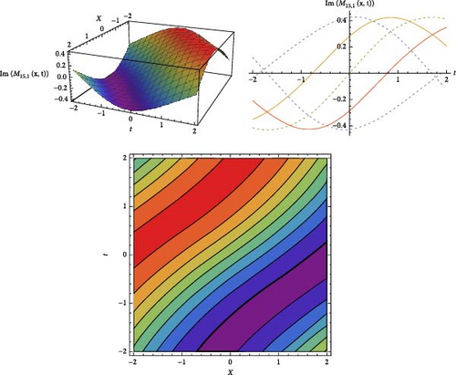
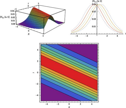
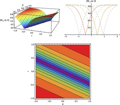
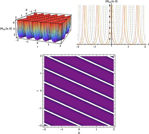
The results and a graphical analysis of a few extracted solutions are covered in this section. Using the JEFE method, the analytical solutions of the HMBS model are extracted. These solutions are effectively extracted as single and mixed waves, and they can be seen in singular, dark soliton, solitary wave, and other forms. Additionally, there are a variety of analytical methods for obtaining the various kinds of solitary wave solutions. A few analytical answers are given to us, together with information on how they behave physically. The solutions are obtained using JEF, which gives us solitary wave behavior when m → 0 and solitons behavior when m → 1. These graphs show various soliton behaviors to show how Wolfram Mathematica 11.1 can be used to physically interpret the JEF technique solutions. M(x, t) and N(x, t) for a few of these solutions are displayed in Figures as 2D and 3D contour graphs for visual demonstration. Figure 1 show the dark soliton behavior for the solution |M1,0(x, t)| and Figure 2 gives us the solitary wave behavior the solution |M2,0(x, t)|. Figure 3 is drawn for the solutions M15,1(x, t) for the imaginary solutions that will gives us the dark–bright solitons clearly. Figure 4 provided us the bright soliton for the |N5,1(x, t)|.
Details are in the caption following the image
Optical dark soliton representation of |M1,1(x, t)| by choosing the constants. b = 2.2, c = 1.99, δ = 0.99, andw = 0.4.
Details are in the caption following the image
Optical form solitary wave representation of |M2,0(x, t)| by choosing the constants. b = 2.2, c = 0.99, δ = 2.99,  andw = 1.4.
Details are in the caption following the image
Optical dark–bright soliton of Im(M15,1(x, t)) by choosing the constants. b = 2.2, c = 0.99, δ = 0.099, andw = 0.4.
Details are in the caption following the image
Optical bright soliton of |N5,1(x, t)| by choosing the constants.s b = 2.2, c = 0.99, δ = 0.099, andw = 0.4.

The theoretically obtained soliton solutions including bright, dark and singular solitons are mathematically precise but it’s important to discuss their practical significance in erbium-doped fiber systems. Bright solitons arise in anomalous dispersion regimes and correspond to optical pulses that retain their integrity and energy over long distances of propagation. Dark solitons, by contrast, represent regions of reduced intensity resting on a background of steady light and are often associated with normal dispersion conditions. Singular solitons exhibit exceptional features either singularities in amplitude or sharp peaks and serve as a precursor to nonlinear instability or as a trace of localized accumulation of energy in fiber systems. Interpreting the derived solitons in terms of experimentally observable parameters, like pulse width, peak amplitude, energy content and propagation speed, helps relate the theoretical results to practical applications. Experimental manifestations of soliton behavior could potentially be extracted from the influence of input power or doping concentration in erbium-doped fibers. Sharing insights into how the proposed model can be implemented in experimental settings using femtosecond and picosecond pulse generation and ultrafast optical diagnostics further highlights both the relevance of the model to fiber optics and its importance in the field of nonlinear photonics. Establishing a direct link between theoretical concepts and experimental measurements greatly increases the real-world relevance of this work.

6. Dynamical Analysis

In this section, we observed the sensitivity, chaotic, and bifurcation analysis of the doubly dispersive an equation. Using the Galilean transformation Equation (17) is converted into dynamical system [31, 32]. Equation (17) is assumed, such as
()
where we let and

6.1. Sensitivity Analysis

Let Q(η) = Q1 and
()
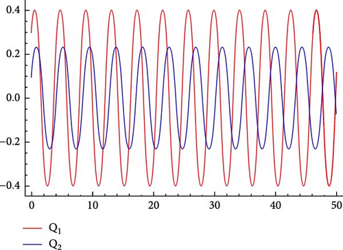
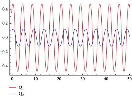
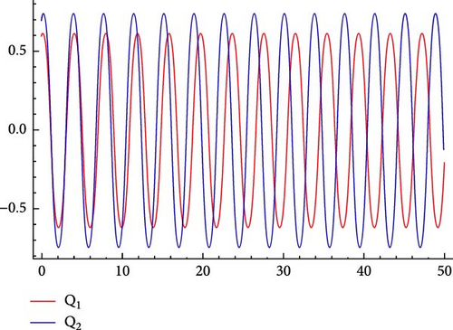
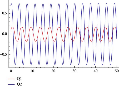
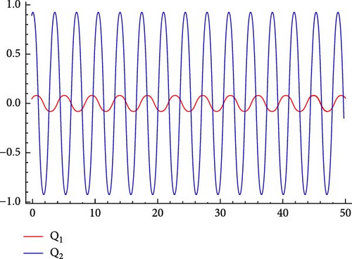
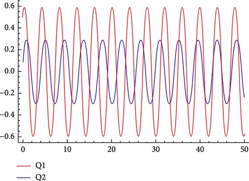
To demonstrate the sensitivity of the dynamical system, we expressed the sensitivity of the solutions in this analysis. If we only make little adjustments to the original conditions, the system sensitivity will be reduced. The sensitivity plots are created using the parameters that were selected, such as τ = 2 and ν = 2. The system will be extremely sensitive, nevertheless, if it changes much as a result of minor changes to the initial conditions. We’ll look at how the frequency term affects the model under study. This will be accomplished by defining the physical characteristics of the model being studied and discussing the effects of the disturbance’s force and frequency on the system. The illustrations Figure 5 illustrate how our dynamical behaves sensitively for varying initial condition values. It displays the sensitive behavior if we alter the initial conditions by changing the slit.
Details are in the caption following the image
Sensitive behavior of the dynamical system (92) for the different values of ICs: (a) IC used for red line (0.3, 0.4) for blue line (0.1, 0.3), (b) IC used for red line (0.4, 0.4) for blue line (0.1, 0.1), (c) IC used for red line (0.6, 0.2) for blue line (0.7, 0.4), (d) IC used for red line (0.1, 0.2) for blue line (0.7, 0.4), (e) IC used for red line (0.05, 0.1) for blue line (0.9, 0.4), and (f) IC used for red line (0.5, 0.5) for blue line (0.09, 0.4).

6.2. Chaotic Analysis

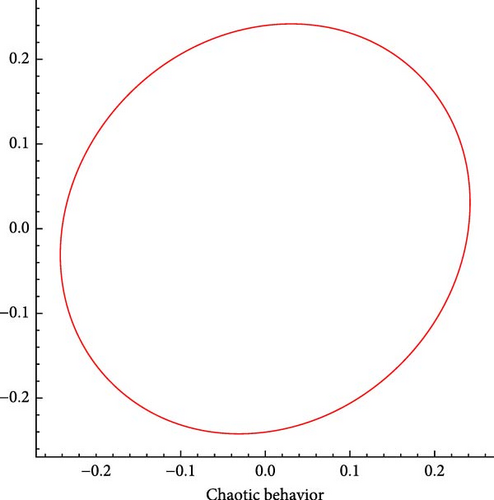
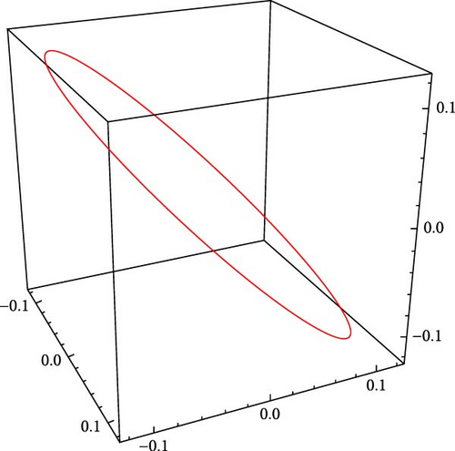
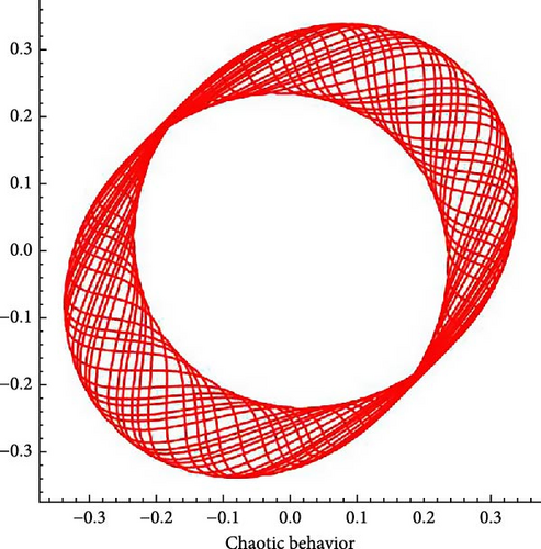
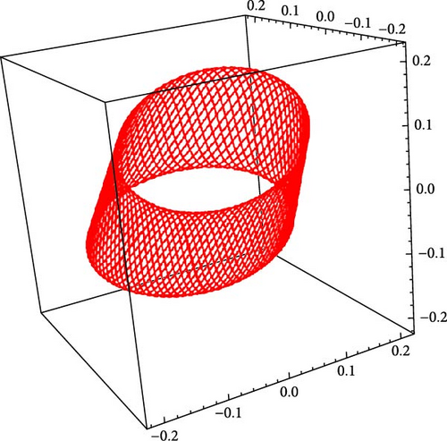
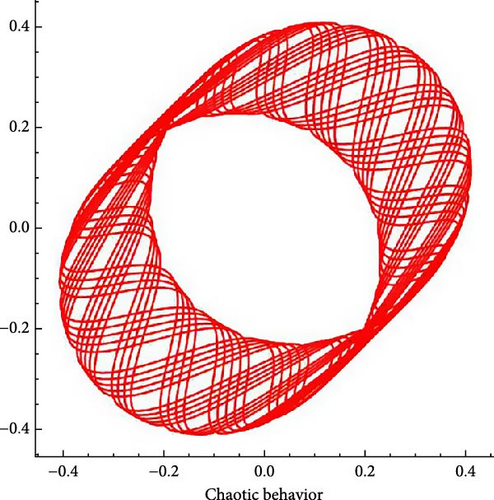
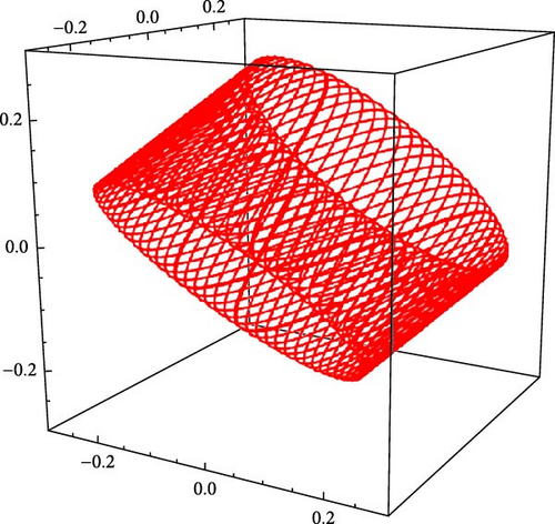
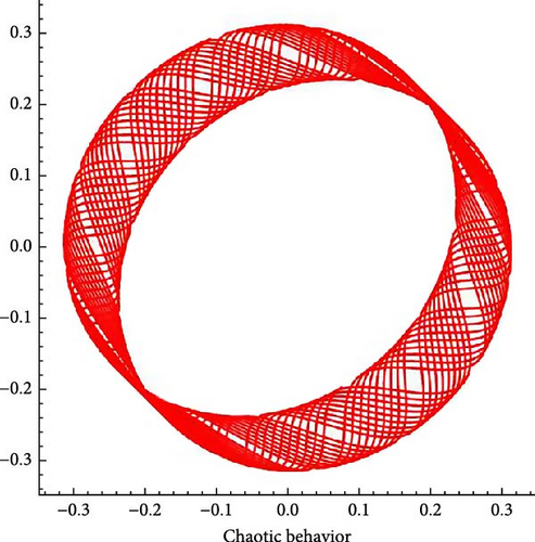
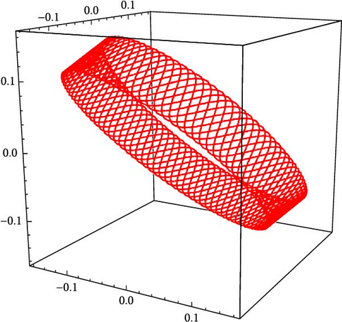
To get the dynamical system (92), using the Galilean transformation to Equation (17). and observing the chaotic behavior by adding χ cos(ϖt).
()
The Figure 6 shows the different chaotic behaviors for the different values of χ and ϖ.
Details are in the caption following the image
Chaotic behavior of the dynamical system (93): (a) 2D chaotic behavior when χ = 0 and ϖ = 2π, (b) 3D chaotic behavior when χ = 0 and ϖ = 2π, (c) 2D chaotic behavior when χ = 1.9 and ϖ = 2π, (d) 3D chaotic behavior when χ = 1.9 and ϖ = 2π, (e) 2D chaotic behavior when χ = 3.3 and ϖ = 2π, (f) 3D chaotic behavior when χ = 3.3 and ϖ = 2π, (g) 2D chaotic behavior when χ = 3.3 and ϖ = 3π, and (h) 3D chaotic behavior when χ = 3.3 and ϖ = 3π.

6.3. Bifurcation Analysis

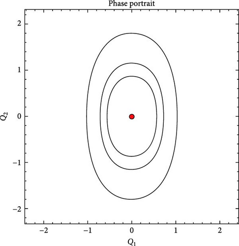
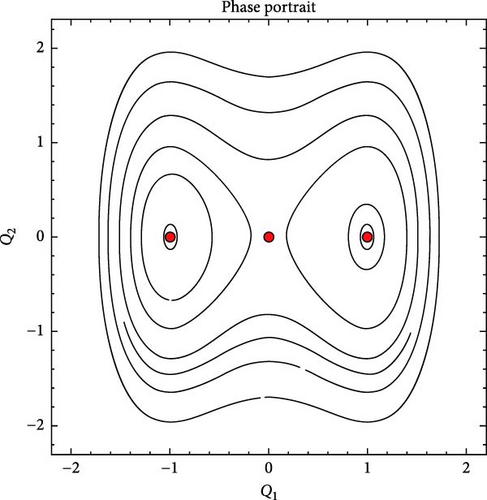
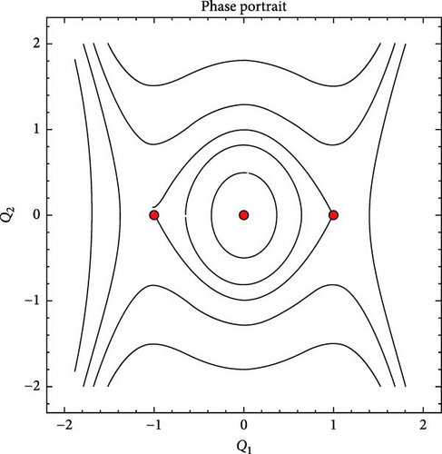
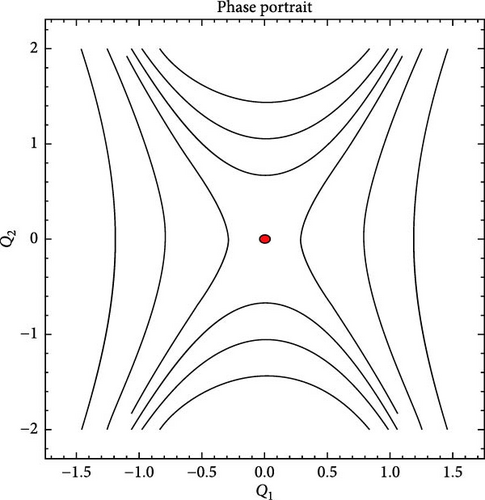
This section will use bifurcation theory [31, 32] to examine Equation (1). This Hamiltonian system has the following integral
()
where q is Hamiltonian constant. In this section, we will look at the bifurcations in the phase portraits of the system (92) in terms of parameters. By qualitative technique, different results are gained. For the system of differential equations mentioned above, the three equilibrium points are calculated as follows: (0, 0), , and on the P1-axis. Also, the Jacobian of the system will be:
Thus (Q1, 0) is a saddle point for J = (Q1, Q2) < 0, it is a center for J = (Q1, Q2) > 0 and a cuspidal point for J = (Q1, Q2) = 0. The bifurcations analysis is shown in Figure 7.
Details are in the caption following the image
Phase portrait behavior of the system (92): (a) phase potrait for τ = 2 and ν = 2, (b) phase potrait for τ = −2 and ν = 2, (c) phase potrait for τ = 2 and ν = −2, and (d) phase potrait for τ = −2 and ν = −2.
Details are in the caption following the image
Phase portrait behavior of the system (92): (a) phase potrait for τ = 2 and ν = 2, (b) phase potrait for τ = −2 and ν = 2, (c) phase potrait for τ = 2 and ν = −2, and (d) phase potrait for τ = −2 and ν = −2.
Details are in the caption following the image
Phase portrait behavior of the system (92): (a) phase potrait for τ = 2 and ν = 2, (b) phase potrait for τ = −2 and ν = 2, (c) phase potrait for τ = 2 and ν = −2, and (d) phase potrait for τ = −2 and ν = −2.
Details are in the caption following the image
Phase portrait behavior of the system (92): (a) phase potrait for τ = 2 and ν = 2, (b) phase potrait for τ = −2 and ν = 2, (c) phase potrait for τ = 2 and ν = −2, and (d) phase potrait for τ = −2 and ν = −2.

Case-1: When we choose τ > 0 and ν > 0 then there is only one real critical point O(0, 0)at which J > 0. So, center point shows in sub Figure 7a.

Case-2: When we choose τ < 0 and ν > 0 then for J < 0 at O(0, 0) and J > 0 both at , and . So point O is saddle and A, B are center points shows in sub Figure 7b.

Case-3: When we choose τ > 0 and ν < 0 then J > 0 at O(0, 0)and J < 0 both at , and . So point O is center and A, B are saddles shows in sub Figure 7c.

Case-4: When we choose τ < 0 and ν < 0 there is only one real critical point O(0, 0) at which J < 0. So, O is saddle point shows in sub Figure 7d.

7. Conclusions

In this work, we are found exact optical soliton solutions for an integrable reduced spin HMBS in this work, which can be used to transmit femtosecond pulses in an erbium-doped fiber. The JEF approach has been successfully applied to the construction of several soliton solutions. Solutions for the JEF were obtained in the following forms: trigonometric, hyperbolic, combination, and single function. A modified form of the JEFE approach, on the other hand, can produce distinct solutions, including mixed, kink, bright, dark, and singular soliton. This approach can therefore be used to discuss the NLPDEs that arise in the theory of soliton and other related fields of study. In order to understand the planar dynamical system and demonstrate its reliance on physical characteristics, such as quasiperiodic and sensitivity analysis, we employ bifurcation and chaos theories. These novel findings provide fresh perspectives on the dynamics of wave motion in mathematical models. We use symbolic computers to handle nonlinear wave issues in a variety of domains, including engineering and mathematical physics. Furthermore, these solutions might be helpful in every area of mathematical physics and engineering equation applications.

Conflicts of Interest

The authors declare no conflicts of interest.

Author Contributions

Asma Taskeen: methodology, writing – original draft, writing – review and editing. Muhammad Ozair Ahmed: supervision, methodology, writing – original draft, writing – review and editing. Muhammad Zafarullah Baber: visualization, investigation, writing – review and editing. Baboucarr Ceesay: visualization, formal analysis, investigation, writing – review and editing. Nauman Ahmed: visualization, formal analysis, investigation, writing – review and editing.

Funding

No funding was received for this manuscript.

Acknowledgments

The authors have nothing to report.

    Data Availability Statement

    Data sharing is not applicable to this article as no new data were created or analyzed in this study.

      The full text of this article hosted at iucr.org is unavailable due to technical difficulties.