Crank–Nicolson Method for Singularly Perturbed Unsteady Parabolic Problem With Multiple Boundary Turning Points
Abstract
In this paper, a numerical scheme for a time-dependent singularly perturbed parabolic convection–diffusion problem with boundary turning points is presented. The problem exhibits a left boundary layer in the spatial domain. We use the Crank–Nicolson method for temporal discretization and a nonstandard finite difference approach for spatial discretization on uniform meshes. Through rigorous error analysis, it has been shown that the scheme is stable and parameter-uniform convergence with a second-order accuracy in time and a first-order accuracy in space. Three model examples are provided to show the applicability of the scheme. It is shown that the numerical results are in agreement with the theoretical findings.
1. Introduction
Time-dependent singularly perturbed parabolic convection–diffusion equations are partial differential equations (PDEs) with the small parameter ε(0 < ε ≪ 1) multiplying the highest derivative term in the PDEs which leads to a stiff behaviour in a certain region of the solution domain. These types of problems arise in the drift–diffusion equation of semiconductor device [1], thermal boundary layers in the laminar flow [2], modelling of transport phenomena [3] and heat flow [4]. It is well-known that the numerical methods using standard finite difference operators on uniform mesh for boundary layer problems give unsatisfactory results of the exact solution unless very fine mesh is used in the approximation process [5]. However, this approach increases the round-off error and the computational cost. These side effects motivated the development of a suitable numerical method whose convergence to the exact solution is independent of the perturbation parameter ε. Some of the parameter uniform convergence numerical methods are fitted operator approach, fitted mesh approach, grid equi-distribution approach and domain decomposition approach. Related to these, one can refer the survey articles on the singularly perturbed parabolic differential equations with boundary turning points [6–14], and the singularly perturbed delay, and the nondelay problem with different boundary conditions [15–33] whose solutions are convergent to the exact solution independent of the perturbation parameter.
Kumari, Kumar and Calle [10] considered singularly perturbed problems including boundary turning points of multiplicity greater than or equal to one. They proposed a numerical scheme comprising the Crank–Nicolson finite difference method in the temporal direction and an upwind finite difference method on Shishkin mesh in the spatial direction. They analysed the scheme for convergent and obtained a second-order accuracy in time and a first-order accuracy in space. Yadav, Rai and Sharma [11] proposed a numerical scheme comprising an implicit finite difference method for time discretization on a uniform mesh and a hybrid scheme for spatial discretization on a generalized Shishkin mesh for solving singularly perturbed parabolic turning point problems. They analysed the method for convergence and obtained second-order accuracy in space except for a logarithm factor and a first-order accuracy in time. These authors used the Richardson extrapolation technique to increase the order of convergence in the time direction. Sahoo and Gupta [12] had developed a first-order ε-uniform convergent scheme for solving singularly perturbed parabolic problems with a boundary turning point. They discretized the time variable using the implicit Euler method on uniform mesh and a simple upwind scheme on piece-wise uniform mesh in space variable. These authors used the Richardson extrapolation technique to increase the order of convergence in both directions. Majumdra and Natesan [13] proposed an ε-uniform hybrid numerical scheme for a singularly perturbed degenerate parabolic convection–diffusion problem consisting of implicit-Euler finite difference method on uniform mesh in temporal direction and the hybrid finite difference method, which is a combination of central difference and midpoint upwind schemes on piece-wise uniform shishkin mesh in spatial direction. They derived the error estimates and obtained ε-uniform convergent of almost a second-order accuracy (up to a logarithmic factor) in space and a first-order accuracy in time.
One can see [34, 35] for more details of existing literature on asymptotic analysis and numerical methods for the turning point problems.
As we observed, the developed schemes enumerated above used the fitted mesh method for solving the problem of type in [10], which requires prior knowledge about the location and width of the boundary layer. Sometimes, this requirement is difficult to be satisfied.
Mbroh and Munyakazi [36] proposed a robust numerical method for solving one- and two-dimensional singularly perturbed parabolic reaction–diffusion problems via method of lines. They discretized first the space variable using fitted operator finite difference method and then integrated in time with the Crank–Nicolson finite difference method. These authors established a second-order accuracy both in time and in space. Ayele, Tiruneh and Derese [37] proposed a numerical scheme to solve singularly perturbed space delay parabolic problem of convection–diffusion type using Crank–Nicolson method in time variable and nonstandard fitted operator method in space variable. Tiruneh, Derese and Tefera [38] proposed a second-order accuracy nonstandard fitted operator numerical scheme to solve singularly perturbed time delay parabolic problem of reaction–diffusion type. Hassen, Duressa and Liu [15] proposed parameter-uniformly convergent numerical method for singularly perturbed delay parabolic convection–diffusion problems using Crank–Nicolson method in time and fitted operator up wind finite difference method in space by applying zeroth-order asymptotic expansion of the exact solution and they have got first order convergence in space and second order convergence in time. Hailu and Duressa [20] proposed parameter-uniformly convergent numerical scheme using Crank–Nicolson finite difference method for the temporal direction and the nonstandard finite difference scheme for the spatial direction on uniform meshes. The Simpson’s integration rule is used to handle the integral boundary condition. They used Richardson extrapolation technique to enhance the order of convergence of the spatial variable. Kumie et al. [22] proposed a first-order numerical scheme to solve time-fractional singularly perturbed delay PDEs using Crank–Nicolson method in time and nonstandard finite difference method in space. Woldaregay and Duressa [39] proposed parameter-uniformly convergent numerical schemes using the nonstandard finite difference method on uniform and Shishkin meshes in space and the Crank–Nicolson method on uniform mesh in time for solving the singularly perturbed convection–diffusion–reaction equation. The schemes on uniform mesh showed better accuracy and order of convergence than Shishkin mesh. Motivated by the work of [20, 22, 39], we aimed to develop and analyse a parameter uniform fitted operator numerical scheme based on the exact finite difference method [40] to solve singularly perturbed parabolic convection–diffusion problem with multiple boundary turning points that does not require the location and width of boundary layer. This approach is also advantageous for easily solving singularly perturbed nonlinear problems and can extend to higher dimensions.
The purpose of this paper is to construct and analyse a numerical scheme that has a better accuracy for solving singularly perturbed parabolic convection–diffusion problems with multiple boundary turning points. We proposed a method of line consisting of Crank–Nicolson method in time and the nonstandard finite difference method in space with uniform meshes to solve the problem of concern. Theoretically, we showed that the proposed scheme has accuracy O(M−2 + N−1), where N and M are the number of mesh intervals in space and in time, respectively.
2. Properties of Continuous Problem
Since only one boundary condition is needed to solve this reduced problem, one boundary condition will be underutilized, resulting in boundary layer in that neighbourhood. The convective term is positive over the domain W, as you can see. The boundary layer will therefore be found close to x = 0. According to Kumari, Kumar and Calle [10], the layer’s width is expressed as .
Lemma 1. The bound on the solution u(x, t) of the continuous problem in Equation (1) is given by
Proof. From Equation (5), we have
Lemma 2 The minimum principle. Let ϝ(x, t) be a sufficiently smooth function defined on W which satisfies ϝ(x, t) ≥ 0, ∀(x, t) ∈ ∂W and Then
Proof. Let the point and Since ϝ(x, t) ≥ 0, ∀(x, t) ∈ ∂W, we have (y, z) ∉ ∂W. The inequality implies that , and Giving that
Therefore,
Lemma 3 Stability estimate. Suppose u(x, t) be the solution of Equation (1), then it satisfies
Proof. Consider the barrier functions
Theorem 1. Under the compatibility conditions of Equations (3) and (4), the problem in Equation (1) satisfies the following bounds for 0 ≤ i + 3j ≤ 4:
3. Formulation of the Numerical Scheme
To obtain the full discrete scheme, first discretize the time variable using Crank–Nicolson method with uniform mesh and then apply nostandard finite difference technique [40] in space variable.
3.1. Temporal Discretization
Lemma 4 Minimum principle for temporal discretization. Suppose ϝj+1(x) be the smooth function satisfying ϝj+1(0) ≥ 0, ϝj+1(1) ≥ 0 and Then and j = 0, 1, 2, …M − 1.
Proof. Let ℓ ∈ ⊖ such that ϝj+1(ℓ) = minϝj+1(x) < 0, ∀x ∈ ⊖, which implies that and .
This contradict the assumption that . Therefore, ϝj+1(x)≥ 0 on
Lemma 5. If uj+1(0) ≥ 0 and uj+1(1) ≥ 0, then
Proof. The proof is similar to the proof in [42].
Theorem 2. Suppose that
Proof. Using Taylor series expansion, we have
Further simplification yields
The local error estimate of each time step contributes to the global error in the temporal semidiscretization which is denoted by Ej.
Theorem 3. The global truncation error for temporal discretization up to jth time level is given by
Proof. Using the local error estimate up to the jth time step, we obtain the global error estimate at the jth time step:
3.2. Spatial Discretization
4. Stability and Uniform Convergence Analysis
In this section, we study the discrete minimum principle, stability and ε uniform convergence for the scheme in Equation (23).
Lemma 6 The discrete minimum principle. The operator defined by discrete scheme in Equation (23) satisfies the discrete minimum principle. That is, let be any mesh function satisfying and ∀i = 1, 2, …, N − 1. Then
Proof. Suppose there exist s ∈ {0, 1, 2, …, N} such that which implies k ≠ 0 and k ≠ N. Also we have and Then,
Therefore, the operator satisfies the discrete minimum principle.
Lemma 7. The solution of the discrete problem in Equation (23) satisfies the bound
Proof. Consider the barrier functions
Using the boundary points, we have
For the interior points, we have
Lemma 8. For ε → 0 and for fixed mesh, it holds
Proof.
Let and then
Applying L’Hospitals rule repeatedly, we have
And
Let and then using L’Hospital’s rule repeatedly, we have the following:
Therefore, for σ ∈ (0, ∞).
Theorem 4. Let Uj+1(xi) and are the solutions of Equations (8) and (23), respectively, and then the error bounds at (j + 1)th time level are given by
Proof. The truncation error in the spatial discretization is
Theorem 5. The solution of the fully discrete scheme in Equation (23) converges uniformly to the solution u(xi, tj+1) of Equation (1), and the error estimate is given by
5. Numerical Results and Discussion
In this section, we present numerical results in the form of tables and graphs to validate the proposed scheme in Equation (23) using MATLAB2015a software package. We considered three numerical examples to verify the applicability of the scheme.
Example 1. Consider the singularly perturbed multiple boundary turning point problem [9]:
Example 2. Consider singularly perturbed multiple boundary turning point problem in [10]:
Example 3. Consider the singularly perturbed multiple boundary turning points problem in [7]:
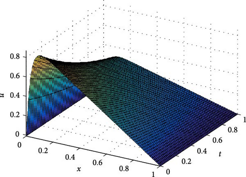
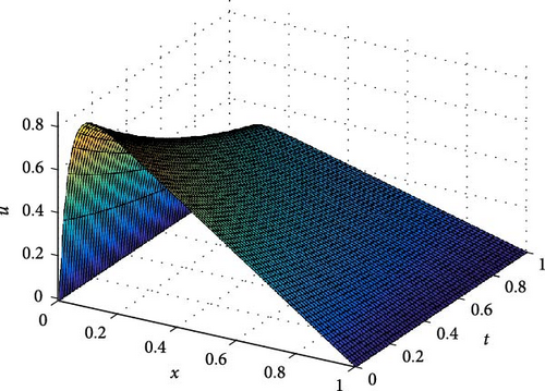
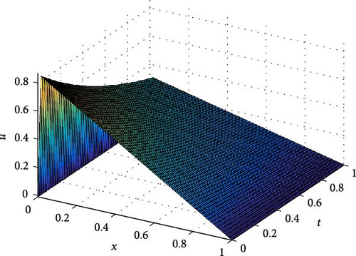
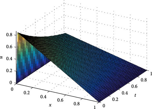
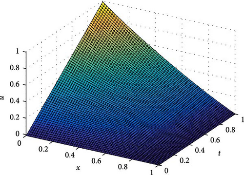
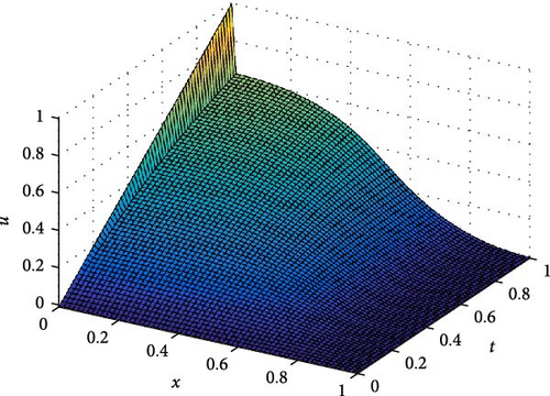
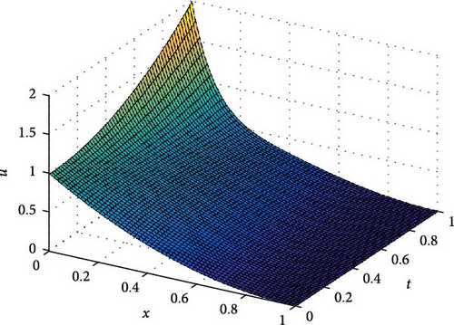
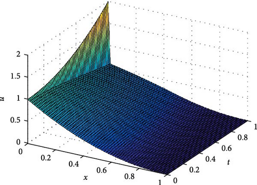
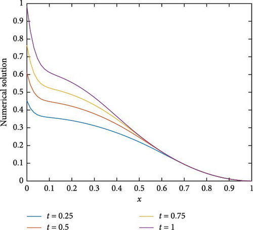
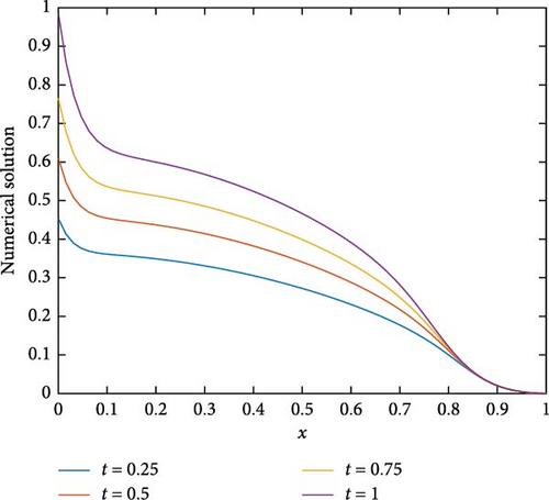
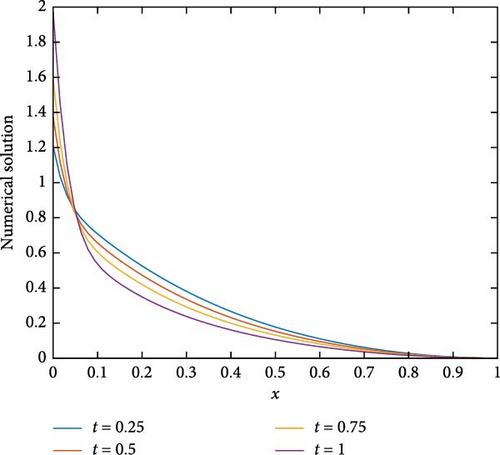
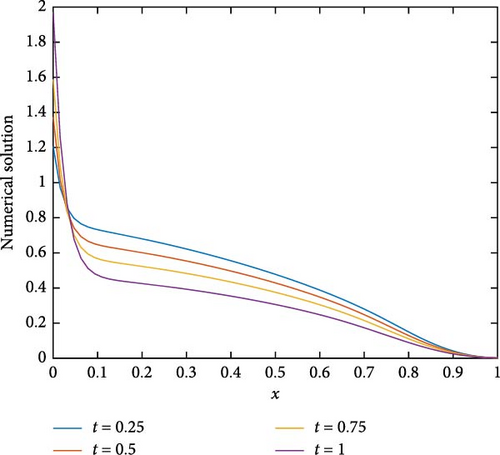
The maximum absolute errors and the rate of convergence of the proposed method for Example 1 at p = 1 are displayed in Table 1. From this table, it is observed that for fixed mesh parameters as the singular perturbation parameter ε decreases to zero, the maximum absolute error is constant, and as the mesh parameter increases, the maximum absolute error decreases. This indicates that the proposed method is ε-uniform convergence. Parameter uniform error and its rate of convergence for Example 1 using different values of p are displayed in Table 2. From the results in this table, it can be observed that the error bound is also independent of p and its order of convergence is first order. Further, Tables 3–5 are displayed to compare the proposed method with the methods in [10] and [7] using model Examples 2 and 3, respectively. From the displayed results, it is shown that the proposed method has better accuracy and order of convergence than the existing different schemes in the literature. Surface plots for each example are displayed using Figures 1–3 for different singular perturbation parameters. The displayed figures show that the solution of the problems exhibits a left boundary layer in the spatial domain. As ε → 0, the thickness of the boundary layer decreases. Also, the numerical solution profiles for different time levels at a fixed ε for Examples 2 and 3 are displayed in Figures 4 and 5, respectively, for different values of p to show the effect of p on the solution.
| ε↓M = N→ | 32 | 64 | 128 | 256 | 512 |
|---|---|---|---|---|---|
| 2−0 | 8.8304e−04 | 4.5397e−04 | 2.3010e−04 | 1.1583e−04 | 5.8110e−05 |
| 0.9599 | 0.9803 | 0.9903 | 0.9951 | — | |
| 2−2 | 1.4197e−03 | 7.5125e−04 | 3.8591e−04 | 1.9552e−04 | 9.8397e−05 |
| 0.9182 | 0.9610 | 0.9810 | 0.9906 | — | |
| 2−4 | 4.0702e−03 | 2.1042e−03 | 1.0685e−03 | 5.3822e−04 | 2.7009e−04 |
| 0.9518 | 0.9777 | 0.9893 | 0.9948 | — | |
| 2−6 | 5.2903e−03 | 2.7155e−03 | 1.3726e−03 | 6.8965e−04 | 3.4562e−04 |
| 0.9621 | 0.9843 | 0.9930 | 0.9967 | — | |
| 2−8 | 5.3771e−03 | 2.7809e−03 | 2.7727e−04 | 7.0952e−04 | 3.5565e−04 |
| 0.9513 | 0.9791 | 0.9915 | 0.9964 | — | |
| 2−10 | 5.3773e−03 | 2.7828e−03 | 1.4144e−03 | 7.1277e−04 | 3.5763e−04 |
| 0.9503 | 0.9764 | 0.9887 | 0.9950 | — | |
| 2−12 | 5.3773e−03 | 2.7828e−03 | 1.4144e−03 | 7.1277e−04 | 3.5763e−04 |
| 0.9503 | 0.9764 | 0.9887 | 0.9950 | — | |
| eN,M | 5.3773e−03 | 2.7828e−03 | 1.4144e−03 | 7.1277e−04 | 3.5763e−04 |
| pN,M | 0.9503 | 0.9764 | 0.9887 | 0.9950 | — |
| p↓M = N→ | 32 | 64 | 128 | 256 | 512 |
|---|---|---|---|---|---|
| 2 | 5.3653e−03 | 2.7814e−03 | 1.4142e−03 | 7.1286e−04 | 3.5785e−04 |
| 0.9479 | 0.9758 | 0.9883 | 0.9943 | — | |
| 3 | 5.3530e−03 | 2.7799e−03 | 1.4140e−03 | 7.1283e−04 | 3.5785e−04 |
| 0.9453 | 0.9752 | 0.9882 | 0.9942 | — | |
| 4 | 5.3402e−03 | 2.7784e−03 | 1.4139e−03 | 7.1281e−04 | 3.5784e−04 |
| 0.9426 | 0.9746 | 0.9880 | 0.9942 | — | |
| 5 | 5.3271e−03 | 2.7769e−03 | 1.4137e−03 | 7.1279e−04 | 3.5784e−04 |
| 0.9399 | 0.9740 | 0.9879 | 0.9942 | — | |
| ε↓M = N→ | 32 | 64 | 128 | 256 | 512 | |
|---|---|---|---|---|---|---|
| 2−0 | PM | 1.0391e−04 | 2.5380e−05 | 6.3168e−06 | 1.5785e−06 | 3.9456e−07 |
| 2.0336 | 2.0064 | 2.0006 | 2.0002 | — | ||
| Method in [10] | 5.16e−04 | 2.69e−04 | 1.38e−04 | 6.95e−05 | 3.49e−05 | |
| 0.94 | 0.96 | 0.99 | 0.99 | — | ||
| 2−4 | PM | 3.5367e−04 | 8.8881e−05 | 2.2251e−05 | 5.5648e−06 | 1.3913e−06 |
| 1.9925 | 1.9980 | 1.9994 | 1.9999 | — | ||
| Method in [10] | 6.42e−03 | 2.56e−03 | 9.98e−04 | 4.09e−04 | 1.79e−04 | |
| 1.33 | 1.36 | 1.29 | 1.19 | — | ||
| 2−8 | PM | 4.3765e−03 | 1.5863e−03 | 4.5374e−04 | 1.1789e−04 | 2.9767e−05 |
| 1.4642 | 1.8057 | 1.9445 | 1.9856 | — | ||
| Method in [10] | 1.22e−02 | 5.68e−03 | 2.704e−03 | 1.31e−03 | 6.73e−04 | |
| 1.10 | 1.07 | 1.04 | 0.96 | 0.98 | ||
| 2−12 | PM | 4.9556e−03 | 2.6327e−03 | 1.3661e−03 | 6.8706e−04 | 3.0147e−04 |
| 0.9125 | 0.9464 | 0.9916 | 1.1884 | — | ||
| Method in [10] | 1.24e−02 | 5.98e−03 | 2.92e−03 | 1.58e−03 | 8.37e−04 | |
| 1.05 | 1.03 | 0.89 | 0.92 | — | ||
| 2−20 | PM | 4.9556e−03 | 2.6327e−03 | 1.3664e−03 | 6.9824e−04 | 4.0519e−04 |
| 0.9125 | 0.9461 | 0.9686 | 0.7851 | — | ||
| Method in [10] | 1.24e−02 | 5.99e−03 | 2.94e−03 | 1.60e−03 | 8.57e−04 | |
| 1.05 | 1.03 | 0.88 | 0.90 | — | ||
| 2−32 | PM | 4.9556e−03 | 2.6327e−03 | 1.3664e−03 | 6.9824e−04 | 4.0519e−04 |
| 0.9125 | 0.9461 | 0.9686 | 0.9820 | — | ||
| Method in [10] | 1.24e−02 | 5.99e−03 | 2.94e−03 | 1.60e−03 | 8.57e−04 | |
| 1.05 | 1.03 | 0.88 | 0.90 | — | ||
| eN,M | PM | 4.9556e−03 | 2.6327e−03 | 1.3664e−03 | 6.9824e−04 | 4.0519e−04 |
| 0.9125 | 0.9461 | 0.9686 | 0.9820 | — | ||
| eN,M | Method in [10] | 1.24e−02 | 5.99e−03 | 2.94e−03 | 1.60e−03 | 8.57e−04 |
| 1.05 | 1.03 | 0.88 | 0.90 | — | ||
| p↓M = N→ | 32 | 64 | 128 | 256 | 512 |
|---|---|---|---|---|---|
| Proposed method | |||||
| 2 | 4.8802e−03 | 2.5150e−03 | 1.2743e−03 | 6.4108e−04 | 3.2150e−04 |
| 0.9564 | 0.9809 | 0.9911 | 0.9957 | — | |
| 4 | 4.5478e−03 | 2.3839e−03 | 1.2162e−03 | 6.1380e−04 | 3.0827e−04 |
| 0.9319 | 0.9709 | 0.9866 | 0.9935 | — | |
| 6 | 3.9892e−03 | 2.1621e−03 | 1.1179e−03 | 2.9815e−04 | 9.8769e−05 |
| 0.8836 | 0.9517 | 0.9779 | 0.9918 | — | |
| Method in [10] | |||||
| 2 | 1.11e−02 | 5.56e−03 | 3.07e−03 | 1.69e−03 | 8.96e−04 |
| 1.00 | 0.86 | 0.86 | 0.92 | — | |
| 4 | 1.11e−02 | 5.59e−03 | 3.26e−03 | 1.81e−03 | 9.60e−04 |
| 0.99 | 0.78 | 0.85 | 0.91 | — | |
| 6 | 1.11e−02 | 5.86e−03 | 3.30e−03 | 1.81e−03 | 9.53e−04 |
| 0.92 | 0.83 | 0.87 | 0.93 | — | |
| p↓M = N→ | 32 | 64 | 128 | 256 | 512 |
|---|---|---|---|---|---|
| PM for eN,M and pN,M (ε—uniform errors) | |||||
| 1 | 4.2861e−03 | 2.2276e−03 | 1.1347e−03 | 5.7213e−04 | 2.8721e−04 |
| 0.9442 | 0.9732 | 0.9879 | 0.9942 | — | |
| 2 | 3.5515e−03 | 1.9370e−03 | 1.0293e−03 | 5.3742e−04 | 2.7716e−04 |
| 0.8746 | 0.9121 | 0.9375 | 0.9553 | — | |
| 3 | 3.9398e−03 | 2.1777e−03 | 1.1643e−03 | 6.0914e−04 | 3.1418e−04 |
| 0.8553 | 0.9034 | 0.9346 | 0.9552 | — | |
| 4 | 4.1942e−03 | 2.3380e−03 | 1.2558e−03 | 6.5790e−04 | 3.3948e−04 |
| 0.8431 | 0.8968 | 0.9326 | 0.9545 | — | |
| 5 | 4.3430e−03 | 2.4465e−03 | 1.3185e−03 | 6.9270e−04 | 3.5760e−04 |
| 0.8280 | 0.8919 | 0.9285 | 0.9539 | — | |
| Method in [7] for ε = 2−15 | |||||
| 1 | 1.6983e−02 | 1.0060e−02 | 5.8145e−03 | 3.3187e−03 | 1.8729e−03 |
| 0.7554 | 0.7901 | 0.8090 | 0.8254 | — | |
| 2 | 5.2597e−03 | 3.1615e−03 | 1.7846e−03 | 9.5309e−04 | 4.9762e−04 |
| 0.7344 | 0.8250 | 0.9049 | 0.9376 | — | |
| 3 | 6.0131e−03 | 3.5487e−03 | 2.0113e−03 | 1.0731e−03 | 5.6104e−04 |
| 0.7608 | 0.8192 | 0.9063 | 0.9356 | — | |
| 4 | 6.7491e−03 | 3.94871e−03 | 2.1852e−03 | 1.1564e−03 | 6.0515e−04 |
| 0.7733 | 0.8536 | 0.9181 | 0.9342 | — | |
| 5 | 7.3137e−03 | 4.2306e−03 | 2.3353e−03 | 1.2144e−03 | 6.3693e−04 |
| 0.8797 | 0.8572 | 0.9434 | 0.9311 | — | |
6. Conclusion
Singularly perturbed convection–diffusion parabolic PDE with multiple boundary turning point problems is considered. The stiffness of this problem is due to the existence of a boundary turning point and the singular perturbation parameter ε. The solution of the considered problem exhibits a left boundary layer on the spatial domain. We developed a numerical scheme to solve this problem using Crank–Nicolson in time and nonstandard finite difference method in space with uniform meshes. The solution behaviour on the perturbation parameter is displayed using figures and tables. These results proved that the proposed scheme is stable and parameter uniform convergence with second-order accuracy in time- and first-order accuracy in space, and the error bound is independent of p. This analysis is also valid for p = 0, but the solution behaviour on the layer region is different from the considered problem. The numerical solution of the considered model examples agreed with the theoretical findings. The proposed method can be extended to solve singularly perturbed parabolic turning point problems with an interior layer and higher dimensions.
Conflicts of Interest
The authors declare no conflicts of interest.
Funding
This research work does not have any financial support.
Open Research
Data Availability Statement
No external data are used in this article.


