Investigation of Knee Torque Dynamics in Single-Leg Transfemoral Prosthetic during Walking Using Mathematical Modeling
Abstract
Transfemoral amputees rely on prosthetic devices to restore their mobility and maintain their independence. However, the design and performance of these devices can significantly affect the amputee’s gait and overall functionality. In this study, we investigate the knee torque dynamics of a single-leg transfemoral prosthetic during walking using a mathematical model that takes into consideration knee friction force (β2), the horizontal component of the ground reaction force (F1), and the vertical component of the ground reaction force (F2). By carrying out model simulation in the MATLAB tool, along with Simulink, we derived the tracking error between the generated knee torque of the transfemoral prosthesis and the knee torque trajectory for a normal human leg. This error was evaluated using the normalized root mean square error (NRMSE) method. Our results show that when β2 = 0.3 N.s.m−1, F1 = 320 N, and F2 = 800 N, a tracking error of NRMSE = 0.342868% occurs. A comparison between the simulated knee torque and a desired knee torque trajectory for a normal leg study in the literature suggests that the tracking error generated will force the amputee to use higher metabolic energy to minimize discomfort while walking. These findings highlight the importance of optimizing the design and performance of transfemoral prosthetic devices to improve the knee torque dynamics and overall functionality of amputees. Our mathematical model provides a useful tool for future research in this field, which could help develop more effective prosthetic devices for transfemoral amputees.
1. Introduction
Lower limb amputations become frequent in the whole world due to various reasons such as accidents, civil wars, explosives, gunshots, diabetes mellitus, peripheral vascular diseases, neuropathy, trauma, and cancer [1, 2]. In fact, the loss of the lower limb causes a lot of inconveniences in the daily life of amputee patients. These peoples face frequent health issues, have lower economic, social, academic participation, and performance rates than people without disabilities [3]. In general, the rehabilitation of an amputee is typically achieved via therapy and prescription of a prosthesis [4]. Indeed, depending on the type and severity of leg amputations, amputee patients need to use a specific type of artificial leg prosthesis. However, most prosthetic devices available on the market cause pain and discomfort to the amputee. Smoother movements are usually hampered by inactivity and by the lack of adaptivity of the prosthetic device to the movement pattern of the patient. Among different types of lower limb prosthetic devices, a transfemoral prosthetic is more commercialized due to the highest number of transfemoral amputees. The prosthetic knee adapted to this type of amputation can be classified into three different types depending on the knee structures [5]. There are purely passive transfemoral prostheses, variable damping, active, and dynamic semiactive prostheses [6]. Indeed, the performance of passive transfemoral prostheses knee joints is limited, due to the fact that transfemoral amputees often have asymmetrical gait and have to walk more slowly than healthy people [7]. This requires the amputee to generate more metabolic energy to compensate for the lost muscles [8]. Variable damping prosthetic knees have internal intrinsically passive actuators and, therefore, they can change dynamically. For instance, it is reported in Refs. [9, 10], that the dynamical behavior of the microprocessor-controlled variable damping prosthetic knee relies on the control of a magneto-rheological damper. This type of prosthetic produces the required breaking knee torque during walking and, therefore, allows the knee to adapt to the gait pattern [11]. It improves gait symmetry and reduces musculoskeletal degeneration of transfemoral amputees to one degree [12]. The research group of Professor Goldfarb’s at Vanderbilt University created a low-extremity prosthesis in 2006, which produced a maximum torque of 86 Nm and was powered by a pneumatic pump. Two years later, they developed another low-extremity prosthesis with a maximum torque of 75 Nm, which used a 150 W BLDC motor and a ball screw. In 2012, they made modifications to the design, incorporating a 200 W class BLDC motor and a three-stage pulley-belt type, resulting in a prosthesis with a maximum torque of 85 Nm [13–19]. Their studies showed that an active prosthesis could be helpful for amputees while moving on stairs or steep slopes. In 2011, the research group of Professor Herr’s at MIT developed a knee prosthesis that could generate 130 Nm of torque and 58 RPM, using a series of elastic mechanisms and cable pulleys. In 2014, they incorporated a 200 W class BLDC motor into the existing series elastic mechanism, resulting in a peak output performance of 120 Nm and a maximum speed of 112 RPM. These advancements opened up the possibility of commercializing an active prosthesis [20–22]. The University of Michigan has developed the Open Source Leg [13], which is capable of delivering a torque up to 120 Nm using an aeronautical rotor, despite its low reduction ratio of (42 : 1). In this model, assembling the actuator is rapid and easy, making this a highly convenient option. This prosthetic limb is fully active and can produce up to 80 Nm of knee joint torque with more than 40 RPM (240 deg/s), enabling amputees to smoothly walk on stairs and steep slopes [23]. Despite its impressive functionality, the prosthetic’s heavy weight and its limited battery life of only 1 or 2 hours have prevented it from being widely commercialized. Indeed, most amputees prefer a lighter prosthetic limb that causes less muscle fatigue, even if its functionality is limited. In fact, dynamically active transfemoral prostheses can inject power in order to provide ankle push-off generation and reduce the extra metabolic energy consumption, as presented in [24–28]. However, the active prosthetic knee is energy-intensive and requires a large actuator, which increases the weight of the prosthetic knee and reduces the battery life. Therefore, there is reluctance among people to adopt a fully active prosthetic limb that weighs more than 4 kg limited battery life [13].
In general, the biological knee provides active and passive torque during walking [29]. However, active or passive microprocessor-controlled prosthetic knees cannot simulate the semiactive model. To address this challenge, recent research efforts have been focused on developing prosthetic limbs that are lighter and can be used for longer periods of time. To achieve these objectives, researchers have been exploring the use of passive components such as springs and hydraulic cylinders in their designs [30, 31]. As walking on level ground or low slopes is the norm for most amputees, with stairs or steep slopes, a transfemoral prosthetic knee with a semiactive dynamic is a solution to improve the walking performance of transfemoral amputees. While analyzing the gait of individuals with transfemoral prostheses, multiple approaches are utilized, including kinematic and kinetic analysis, electromyographic (EMG) measurements, and other techniques [32]. Electromyographic (EMG) measurements require a time-consuming process of attaching skin markers and electrodes to the body of the examined patient. Hence, combining kinematic and kinetic analyses could have a considerable advantage in analyzing the dynamic of transfemoral leg prosthetics. In fact, it is reported in [33] that, when kinematic and kinetic analyses are combined, inverse dynamics can then be utilized to obtain variables such as torques in individual joints of lower limbs. Generally, the term gait in prosthesis leg movement analysis describes the style of walking, rather than the walking process itself [34]. At present, there are two approaches to analyzing the dynamics of lower limb prostheses. The first one is a neuromuscular model, which is based on muscle mechanics and the second one is a mathematical model, which is based on the prosthesis parameters. In fact, in Ref. [35], a neuromuscular model of human motion is proposed and a prosthesis controller using muscle reflex and local feedback is designed. Numerical simulation of this model has shown that the neuromuscular control model results in a more robust gait than the one obtained by the impedance control method and improves the amputee’s movement. However, neuromuscular models are not suitable for transfemoral prostheses because of the need to consider coordinated movement between muscles due to serious muscle loss of transfemoral amputees. In general, the Lagrange formalism is the main method to derive the mathematical model of prosthesis devices. In concrete terms, the Lagrangian formulation describes the behavior of a dynamic system in terms of kinetic and potential energy stored in the system rather than of the forces and moments of the individual members involved. The forces (i.e., constraint forces), that restrict the motion of the knee joint within the prosthesis do not appear in the formulation of the Lagrangian dynamic equations. In [36], for example, the motion equations that describe the dynamic of Active Knee Prosthesis are derived through the Euler–Lagrange formalism. In addition to this, a knowledge-based fuzzy inference system is established using the lower limb data to control the dynamic motion of the active knee prosthesis. Researchers in Ref. [37] designed a robot to test transfemoral prostheses. Then, the Lagrange method was used to establish the mathematical model of the robot. Moreover, the authors have shown that the signals of hip displacement and thigh angle can be applied to the robot, and the sliding mode controller can track the position of the hip joint. In [38], the method to describe the forward kinematics of prosthesis has been proposed using a combination of Lie group, Lie algebra, and Lagrange equation to derive a mathematical model of the transfemoral prosthesis. Furthermore, switching control rules were designed to help amputees have normal gait at different phases.
2. Methods
The key improvement of the transfemoral prosthetic knee is to include ground reaction forces and knee friction and to simulate the knee torque. Moreover, combining kinematic and kinetic analyses could have a considerable advantage in analyzing the knee torque trajectory. Moreover, when kinematic and kinetic analyses are combined, inverse dynamics can then be utilized to obtain the torque in the knee joint of the transfemoral prosthetic.
2.1. Parameterized Model of the Transfemoral Prosthetic
As shown in Figure 1, a parameterized model of the transfemoral prosthetic was adopted to simulate the knee torque trajectory. In this model, the transfemoral prosthetic is represented by a two-segment single-axis knee joint.
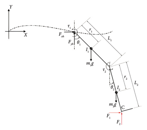
Subscripts i = 1 and i = 2 denote the thigh and shank, respectively, such as mi are the masses, ri represent the distances of the mass centers from the respective proximal joints; Ii are the moments of inertial; Li are lengths; θi are the absolute angular displacement of the thigh and shank from the vertical; τi represents the torques applied to the hip and knee; and Fi are the ground reaction forces. Also, (xh, yh) are the coordinates of the hip with respect to the global reference frame XY. To be more specific, xh represents the horizontal movement of the hip, and yh is the vertical movement of the hip while Fxh and Fyh are the forces acting at the hip joint by the socket.
- (1)
The transfemoral prosthetic and the remaining part of a natural leg are both considered as two rigid segments linked to the amputee’s body with two pin joints.
- (2)
The model only considers the sagittal plane motion.
- (3)
The ankle joint is considered to be fixed.
- (4)
The hip joint is assumed to be actively controlled by the patient.
2.2. Inverse Dynamics of the Transfemoral Prosthetic
The use of the inverse dynamics method plays an important role in this research to derive the equations of motion for transfemoral single-leg prostheses due to its global nature and ability to provide detailed insights into the biomechanics of the system. In addition, it is sensitive to input data such as inertial parameters, kinematic derivatives, joint center positions, and center of pressure [40]. To be more explicit, this method calculates the net forces and torques at each joint, using the coordinates of the center of mass of each link (x1, y1) and (x2, y2) given by equations (1) and (2). By exploiting known kinematic data, such as joint angles and their derivatives, inverse dynamics can accurately trace the movements and performance of the prosthetic limb. This method effectively deals with the complex interactions between the hip and knee, described by the angles θ1 and θ2.
It is important to note that the model (17) is represented as the robotic pendulum model, as considered in previous works [43–48] that address various control strategies and perturbation attenuation techniques for similar systems.
2.3. Comparison of the Developed Model with the Old Model
The model developed in the present study emanates from the previous model proposed in [39], where a transfemoral prosthetic leg is modeled as a single axis of two segmental prosthetic knees implemented with a magneto-rheological (MR) damper as a variable damping element. By carrying out a dynamic analysis of the knee of the transfemoral prosthetic via the inverse dynamic approach, the authors reported that the dynamic model of the transfemoral prosthetic can predict the kinetic and kinematic performances, which can help to trace the desired knee torque trajectory. However, in their work, they did not consider the effects of ground reaction forces as well as the effect of the friction generated by the blade rotation located within the knee joint. In this respect, we extended their model to the realistic context by considering that the friction of the blade generated during the rotation of the center of the knee joint axis, and ground reaction forces are relevant. This consideration incurs three additional terms in the time evolution equation for the transfemoral prosthetic knee torque (see (16) for instance), in contrast to the one proposed in Ref. [39]. These terms are, namely, knee friction force, horizontal ground reaction force, and vertical ground reaction force. To our knowledge, this is the first theoretical work aimed at understanding the impact of these parameters on knee torque dynamics. The presence of these parameters can guide prosthesis designers in selecting appropriate actuators for use in the transfemoral prosthesis knee to improve performance and reduce energy expenditure for the user.
3. Results and Discussion
3.1. Variation of Steady State Knee Torque with Shank Angular Displacement in the Presence of Ground Reaction Forces
As stressed above, we will follow our assumption which states that the patient can actively control his or her hips and only pay attention to the differential (16) of the knee joint’s motion in the presence of friction and ground reaction forces. The data for the prosthetic leg used in the simulation is shown in Table 1 and the inputs to the model such as thigh, and shank angular displacements, their derivatives, as well as hip joint accelerations, are obtained from winter [49]. The whole weight of the prosthesis is around 2.5 kg as reported in [39].
| Parameters | Values |
|---|---|
| Body weight | 80 kg |
| Body height | 1.75 m |
| m2 | 3.46 kg |
| I2 | 0.108 kg·m2 |
| L1 | 0.314 m |
| L2 | 0.425 m |
| r2 | 0.2576 m |
| g | 9.81 m/s2 |
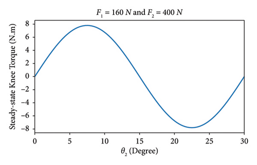
The expression of τ2 given in formula (18) does not include the knee friction coefficient β2, but rather it is primarily controlled by the shank angular displacement θ2. Therefore, to investigate the relationship between the knee torque τ2 and the shank angular displacement θ2, we have chosen to plot their respective values for fixed forces F1 = 160N and F2 = 400N, using the parameter values specified in Table 1. It is worth mentioning that the decision to assign a greater magnitude to the vertical ground reaction force F2 compared to the horizontal component F1 is based on experimental evidence, which demonstrates that the vertical ground reaction force plays a more significant role in knee joint movement than the horizontal component. By analyzing the resulting curve in Figure 2, we observe that as the shank angular displacement θ2 increases, the steady-state knee torque trajectory follows a natural gait pattern. Notably, during the increasing phase of θ2, the knee movement remains stable. This insight holds significant physical relevance, as it indicates that within the range of θ2 values at the steady state, the knee torque trajectory facilitates smooth transitions between flexion and extension, thereby ensuring stability and preventing falls or stumbling.
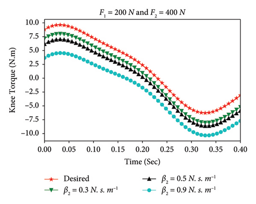
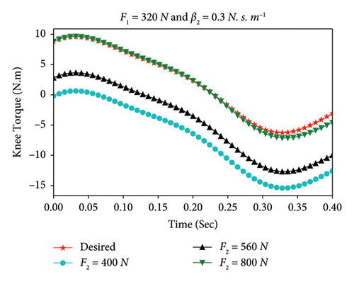
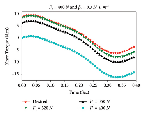
Using implementations under MATLAB and the Simulink toolbox and the differential equation of motion given by (16), the torque provided by the transfemoral prosthetic knee is simulated. The results are shown in Figures 3 and 4 for different values of prosthetic knee friction coefficient and ground reaction forces. Figure 3 represents the variations of the prosthetic knee torque, τ2, as a function of time, for different values of prosthetic knee friction coefficient (β2). In this case, the ground reaction forces have been fixed to F1 = 200 N and F2 = 400 N. According to Figure 3, when β2 is increased in relatively large values, τ2 decreases in time, and the tracking errors between the desired knee torque pattern and the simulated torque trajectory of the transfemoral prosthetic knee increases. To be more explicit, the damping phenomena induced by the blade rotation incorporated into the knee center of rotation of the prosthetic during the dynamic process of the knee are clinically relevant. In fact, this limits the prosthetic knee’s ability to produce optimal knee flexion-extension. Consequently, amputees may need to expend high metabolic energy to modify their gait to walk, leading to modifications in gait patterns that can result in a slower and less symmetrical gait in the swing phase.
The quantity β2(th) represents a threshold value for the friction coefficient, above which the transfemoral prosthetic knee torque tracking error may occur.
| F1 | F2 | β2 | NRMSE (%) |
|---|---|---|---|
| 200 | 400 | 0.3 | 1.00966 |
| 0.5 | 1.48975 | ||
| 0.9 | 2.77402 | ||
| 320 | 400 | 0.3 | 5.63867 |
| 560 | 3.83856 | ||
| 800 | 0.342868 | ||
It is important to note that, the desired knee torque (i.e., in red color), shown in Figures 3 and 4 is plotted based on the experimental data provided in Ref. [49] for the normal leg. This corresponds to the case where β2 = 0, F1 = 0, and F2 = 0 in the present work. Indeed, these variables represent specific conditions in which the knee joint is not subject to any friction and external forces.
4. Conclusions
The dynamics of the knee joint of a transfemoral prosthetic leg were investigated, with a focus on the effects of prosthetic knee friction and ground reaction forces on the temporal profiles of the prosthetic knee torque. The mathematical model of the transfemoral prosthetic knee torque was derived using the inverse dynamics method. Simulation results have demonstrated that incorporating knee friction and ground reaction forces in the model proposed in Ref. [39] leads to tracking errors (see Table 2 for instance) in the prosthetic knee torque trajectory, which results in increased metabolic energy costs for the amputee. To this end, an optimal control problem must be formulated for the three parameters to avoid tracking errors in the knee torque dynamics.
Disclosure
The responsibility for the content of this publication lies with the author.
Conflicts of Interest
The authors declare that they have no conflicts of interest.
Acknowledgments
This paper is based on the DAAD project 57611107 that has received funding from the Federal Ministry of Education and Research (BMBF). The first author wishes to thank the German Academic Exchange Service (DAAD) and the Institute for Automation and Systems Engineering at the Technische Universität Ilmenau, Germany, for a visit during which part of this work was completed. The second author would like to express his sincere gratitude to Alexander von Humboldt and the German Academic Exchange Service (DAAD) for their generous support, which has been instrumental in the successful completion of this research project. The two authors would also like to thank the organizing committee of the conference: International African Conference on Machine Learning, Optimization, and Applications (MLOA) (July 2023), which enabled them to present the first version of this work.
Open Research
Data Availability
The processed data used to support the findings of this study are included within the present article. The original contributions presented in the study are included in the article; further inquiries can be directed to the corresponding author.


