L1 Adaptive Fault-Tolerant Attitude Tracking Control of UAV Systems Subject to Faults and Input Saturation
Abstract
This paper investigates an adaptive fault-tolerant control scheme for an unmanned aerial vehicle (UAV) attitude control system in the presence of multiple faults, input saturation, and external disturbances. The attitude control system of a UAV is divided into an outer loop consisting of attitude angles and an inner loop consisting of attitude angle velocities. The nonlinear dynamic inversion (NDI) method based on sliding mode surface is used to construct the outer loop controller to ensure fast response and accurate attitude tracking. The treatment of the inner loop with multiple faults, input saturation, and external disturbances is more complex. First, input saturation and sensor faults are converted successively for ease of analysis. After the conversion and reorganization of such uncertainties including actuator faults, sensor faults, input saturation, and external disturbances, a nonlinear uncertain system model is developed. Second, a L1 neural network adaptive fault-tolerant controller is designed to deal with uncertainties, where radial basis function neural networks (RBFNNs) are applied to approximate the nonlinear function in the system model. The L1 adaptive fault-tolerant controller includes three parts: state predictor, adaptive law, and control law. Adaptive laws based on the projection operator estimate and update the unknown parameters in the system and transfer them to the control law and the state predictor to compensate for the effects of uncertainties. The control law with a low-pass filter also eliminates the high-frequency oscillations caused by a high adaptive gain in conventional adaptive algorithms, which guarantee the robustness and fast self-adaptation. Finally, simulation results are given to verify the effectiveness and feasibility of the proposed controller.
1. Introduction
Unmanned aerial vehicles (UAVs) have been used progressively in many applications due to their mobility, versatility, and lowered casualty in recent years. Along with that, the accident rate of UAVs is also inevitably rising year by year. These accidents occur mainly in actuators, sensors, and other constituent parts of UAV systems such as the engine and wings. The faults of actuators and sensors are the most common among them. There has been a proliferation of research results dealing with actuator faults or sensor faults, especially the former. A finite-time sliding mode fault-tolerant control method and a neural network-based adaptive fault-tolerant control scheme are investigated for actuator faults in [1, 2], respectively. The predictive descriptor observer is designed in [3] to deal with sensor faults and compensate large delay. Researchers have continued to be concerned about simultaneous faults of actuators and sensors [4–8]. These research results of actuator and sensor faults rely mainly on fault information obtained from fault detection or estimation, which may make the structure of fault-tolerant controllers more complex.
Input saturation is a physical limitation prevalent in the actual actuator mechanism, which is a nonlinear constraint. It has been studied for a long time, and many effective methods are applied to compensate for performance degradation caused by input saturation and environmental constraints [9–13]. In [14], a sigmoid-type function is applied to tackle the input saturation, and a discrete-time disturbance observer is proposed to ensure the boundedness of virtual control signal. The problem of actuator saturation nonlinearity is solved by an improved Gaussian function and an auxiliary compensation system in [15]. For attitude tracking problem of quadrotor UAVs with input saturation and disturbances, a low-computation adaptive neural network technology and an auxiliary system are introduced to deal with external disturbances and input saturation in [16, 17]. Similarly, an auxiliary system is constructed to compensate for the effects of input saturation in [18–20]. For uncertain quadrotor systems with thrust saturation, [21, 22] utilize a differentiable function to design the translational thrust so that it is maintained within a predesigned boundary. In addition to function approximation and auxiliary systems, designing antisaturation controllers is also a well-proven method [23].
The attitude control system is the foundation and key part of the whole flight control system. Its reliability and safety directly affect whether the UAV can fulfill the flight mission normally. In order to avoid coupling between state variables and reduce the design difficulty, the dual-loop design of the attitude control system is a simple and effective method [24–26]. In addition, the attitude control of aircraft under faults has also been paid more and more attention. The attitude tracking problem of multiple UAVs with nonaffine nonlinear faults is investigated in [27], where the neural networks and the Butterworth low-pass filter are introduced to deal with unknown nonlinearities and actuator faults. The fault-tolerant attitude tracking controllers are proposed in [28, 29] to solve the problem of actuator faults and input saturation. Based on the consideration of actuator faults, external disturbances, and measurement errors of attitude angles and angle velocities of rigid-flexible coupled spacecraft, an adaptive fault-tolerant attitude tracking control is investigated in [30]. Looking at the existing research results on fault-tolerant control of attitude tracking systems, it is easy to see that most of these researches are limited to one or a few abnormal conditions. When anomalies outside the scope of coverage arise, the controller may reduce efficiency or even fail completely. The scenarios of actuator faults, sensor faults, input saturation, and external disturbances are possible anomalies of the UAV systems, which are very likely to occur at the same time. Therefore, the fault-tolerant control of UAV systems under multiple faults, input saturation, and external disturbances plays a crucial role in enhancing the reliability and safety of the systems. However, dealing with numerous anomalies at the same time is quite a difficult issue because of the different generation mechanisms, coupling, and influence. Nowadays, fault-tolerant control methods based on fault detection or estimation are widely used. External disturbances are mostly handled in the similar way. It is difficult to design so many observers or estimators when actuator faults, sensor faults, and external disturbances occur simultaneously. Not to mention the need to consider the role of input saturation. Based on the above considerations, a new fault-tolerant control scheme for UAV attitude control systems is proposed in this paper. The dual-loop control structure consists of a sliding mode nonlinear dynamic inverse controller in the outer loop and a L1 neural network adaptive controller (L1NNAC) in the inner loop. The nonlinear dynamic inverse control based on the sliding mode surface ensures the fast response and precise attitude tracking. Through transformation and reorganization, input saturation, sensor faults, actuator faults, and external disturbances are regarded as a lumped uncertainty and the L1 adaptive controller is designed to compensate its effects. The L1 adaptive control algorithm is a deformation of the model reference adaptive control (MRAC). By introducing a low-pass filter in the control law, the L1 adaptive controller can not only handle the uncertainties of systems effectively but also eliminate the high-frequency oscillations due to high gains. In recent years, the L1 adaptive control algorithm has been increasingly used in fault-tolerant control to ensure fast adaptation and robustness of the closed-loop system [31–34].
- 1.
Compared with [2–4, 28–30] dealing with a few types of faults, this paper investigates a more encompassing fault-tolerant control scheme that addresses most of the aircraft anomaly conditions, including actuator faults, sensor faults, external disturbances, and input saturation.
- 2.
Unlike the direct or indirect estimation of faults and external disturbances in [1, 3, 5, 6], this paper views faults and external disturbances as a lumped uncertainty with the help of a low-pass filter and the state expansion approach and utilizes L1 adaptive to compensate for the effects of the uncertainty. The entire fault-tolerant controller does not require the values of faults and external disturbances. This advantage makes the fault-tolerant controller simple in structure, since there is no need to design observers or estimators for faults and disturbances.
- 3.
In contrast to the auxiliary system or saturation dynamic filter approaches in [10, 18–20, 23], the input saturation problem in this paper is solved by a combination of nonlinear function approximation and the median theorem, which better integrates and simplifies the design process of the adaptive fault-tolerant controller. Meanwhile, the steady-state and transient performance analysis of the closed-loop system is accomplished by introducing a L1 reference system, which provides a theoretical basis for improving the system performance.
The rest of this paper is organized as follows: the problem formulation is described in Section 2. In Section 3, the design of a dual-loop controller for a UAV attitude tracking system is presented. Performance analysis of the fault-tolerant controller is given in Section 4. Simulation results are shown in Section 5. Finally, some conclusions are given in Section 6.
2. Problem Formulation
The goal of this paper is to design a fault-tolerant controller such that the output y1 can track the given input signals of attitude angles in presence of faults, input saturation, and external disturbances.
To design the fault-tolerant controller, the following assumptions and lemma are needed:
Assumption 1. There exists Bf > 0, such that |f(t, 0)| ≤ Bf(t ≥ 0).
Assumption 2. For arbitrary δ > 0, there exist , and the partial derivatives of f(t, x2) are semiglobal uniform bounded:
Assumption 3. There exists a constant L0 > 0 such that hold uniformly in t ≥ 0.
Remark 1. f represents the system nonlinearity from (2). Assumption 1 indicates that this nonlinearity is bounded, and the piecewise continuity and boundedness of its partial differentials are demonstrated in Assumption 2. These two assumptions are reasonable because the system nonlinearity depends on the aerodynamic parameters, whereas all parameters are continuous and bounded when the UAV is flying normally within the flight envelope. Assumption 3 is the Lipschitz condition, which is needed later to derive the performance boundaries of the closed-loop system.
For a stable proper MIMO system H(s) with input r(t) and output y(t), there exists an arbitrary time , such that .
3. The Design of Fault-Tolerant Controller
In this section, a dual-loop adaptive fault-tolerant controller is designed to counteract various uncertainties in UAV attitude control systems, including an outer-loop nonlinear dynamic inversion (NDI) controller based on a sliding mode control (NDI-SMC) and an inner-loop L1NNAC. The fault-tolerant controller structure is shown in Figure 1.

3.1. Design of the Outer Loop Controller
The NDI algorithm is a frequently applied feedback linearization method, which is characterized by simplicity, effectiveness, and fast response. However, the existence of various uncertainties in UAV systems makes it difficult to achieve optimal control with conventional NDI. Therefore, here, the conventional NDI algorithm is improved by introducing the control law based on an integral sliding mode surface to enhance the robustness.
Remark 2. In general, intelligent algorithms, neural networks, and fuzzy logic systems are common methods for tuning parameters. Considering the timeliness of fault-tolerant control, this paper selects the parameters in advance by simulation experiments. It has been observed that k0, k2 generally affects the performance of the system in terms of overshoot, oscillation, steady-state error and others. At the same time, larger k1 causes stronger system oscillations, so k1 is usually set to a smaller value.
3.2. Design of the Inner Loop Controller
A L1NNAC algorithm is applied to construct the inner loop controller. Due to the presence of nonlinearities and input saturation, the inner loop nonlinear model in (2) is first linearized here. A function approximation approach is employed to deal with the input saturation function.
It can be seen from (13) that the input saturation function is transformed into a time-varying system with parameter uncertainties and disturbances based on a function approximation approach and the Lagrange median theorem.
There are sensor faults in the system (2) in addition to input saturation and actuator faults. In order to be easily handled together with actuator faults, sensor faults are here converted to pseudoactuator faults using the expanded state-variable method.
In summary, the L1NNAC for the inner loop has been designed, which is composed of the state predictor in (21), adaptive laws in (22), and the control law in (23).
Remark 3. For C2(s) in (23), it should be a strictly proper system with C2(0) = 0. The design of low-pass filters in L1 adaptive control is an open problem. Some effective methods are used to construct low-pass filters such as optimization methods [37] and fuzzy logic systems [38]. For simplicity, C2(s) is defined as [35]
Remark 4. Define, and γδ is an arbitrary positive constant. To guarantee the stability of the closed-loop system, C2(s) are also designed to satisfy that, for a given ρ0, there exists ρr > ρ0 such that the following L1-norm condition holds:
Meanwhile, the L1-norm condition (25) can be further simplified based on Assumption 2 to facilitate the selection of the low-pass filter parameters. Define and combine with the L1-norm condition in (25) that, for all x2 ∈ Rn, the relationship holds: and the L1-norm condition (25) can be simplified to . By substituting the low-pass filter (24) into the above one, the boundary of ϖ can be estimated, and then, the appropriate parameter value can be selected by means of experimental simulation.
Remark 5. kg is designed according to the principle of MRAC. Consider the following ideal reference model for the system (19): , its frequency domain form is . It is obvious that when s⟶0, kg can be chosen as in order to achieve .
4. Analysis of Fault-Tolerant Controller
The following Lemma 2 proves that the L1 reference system is stable.
Consider the L1 reference system (26) subject to the L1-norm condition in (25), if , then
From (19) and (21), the prediction error equation is got:
The minimum estimation error of RBFNN is defined as
So, (29) can be rewritten as
From (20), (31) is organized as
Theorem 1. For the closed-loop system ((19)) with a L1 adaptive fault-tolerant controller consisting of ((21)), ((22)), and ((23)), subject to the L1-norm condition ((25)), if
Proof 1. The Lyapunov function is chosen as follows:
By calculation, is obtained as
From (32) and (22), the upper bound of is derived:
When P2 in the adaptive law (22) is designed, is easy to realize. Therefore, (37) can be rewritten as follows:
From the continuity of V, one can be obtained:
Considering (33) and Barbalat’s lemma [40], one gets
Equation (40) implies that the estimation error of is bounded, so (34) can be deduced. Next, the following theorem explores the performance bounds of the closed-loop system.
Theorem 2. For the given system ((19)) and the L1 adaptive fault-tolerant controller consisting of ((21)), ((22)), and ((23)), subject to the L1-norm condition ((25)), and the L1 reference system ((26)), if , then
Proof 2. Suppose (42) and (43) do not hold, then consider and the continuity of and vad2, there exist τ > 0, such that
Equations (45) and (46) imply that
Recalling Lemma 2, the following relationship is derived:
It follows from Theorem 1 that (41) is proved.
The control law of (23) can be derived as
By further sorting out (49), one gets
Combining with (20), the frequency domain form of the state equation of (19) is obtained as
It is yield from (29) and the definition of in (49):
From Lemma 1, (53) can be rewritten as
From Assumption 3 and (25), it gets
By substituting (55), (54) can be further derived as
Combining (41) and the definition of , (42) is proved.
It is from (50) and the control law in (26) that
Considering the definition of H1(s), the following relationship is yield:
From Lemma 1 and Assumption 3, (57) is derived
So, (43) is proved. From the closed-loop system (19) and the L1 reference system (26), one has that
5. Simulation Examples
In order to verify the effectiveness of the proposed controller, the following four scenarios are carried out. Scenario 1 shows the simulation of the UAV subjected to input saturation and external disturbances, when the actuators and sensors are in normal operation. Scenarios 2 to 4 demonstrate the simulation of the UAV subject to input saturation and external disturbances under three fault modes: sensor faults, actuator faults, and simultaneous sensor faults and actuator faults. In order to highlight the fault tolerance of the proposed L1 adaptive controller (denoted as L1), Scenarios 2 to 4 add a comparison with the attitude angle tracking performance of the MRAC.
5.1. Scenario 1: No Fault
In this scenario, actuators and sensors are working normally, and the UAV suffers from input saturation and external disturbances. The simulation results are shown in Figures 2, 3, and 4.
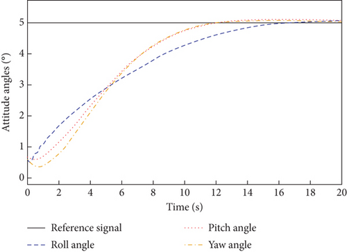
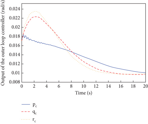
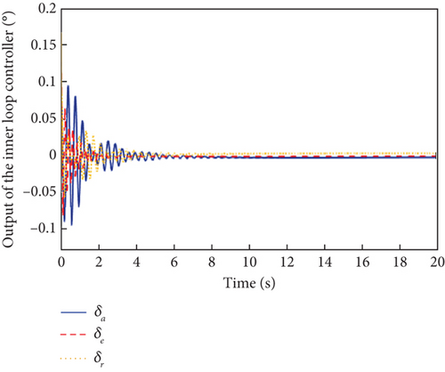
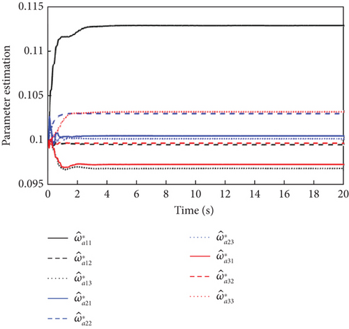
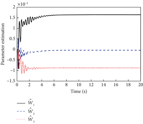
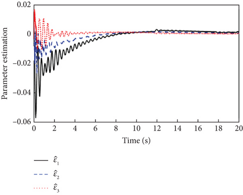
Figures 2, 3, and 4 show the attitude angle tracking, the outputs of inner and outer loop controller, and the parameter estimation curves of L1 adaptive controller, respectively. From Figure 2, it is seen that the attitude tracking performance in the presence of input saturation and external disturbances is good, with small overshoot and fast response. The control outputs of both the outer and inner loops in Figure 3 are smooth and convergent. As can be seen from Figure 4, bounded and fast estimation of adaptive parameter and ε are achieved by projection operators.
Based on the above simulations, the following three scenarios are designed for simulation to verify the fault tolerance of the proposed controller: sensor faults, actuator faults, and simultaneous sensor faults and actuator faults.
5.2. Scenario 2: Sensor Faults
The sensor faults are considered Δf = [0.01, 0.01, 0.01]T, and the simulation results are shown in Figures 5, 6, and 7.

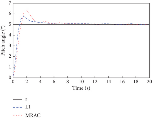
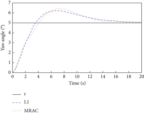
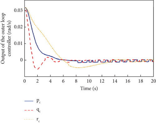
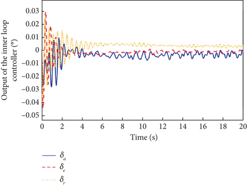
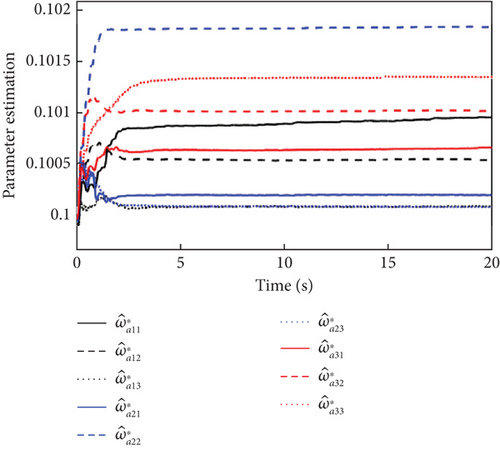
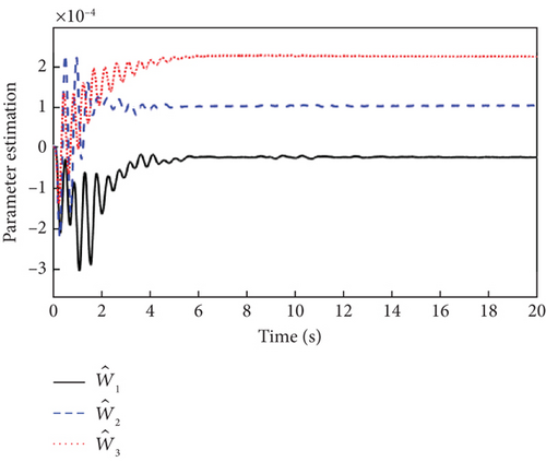
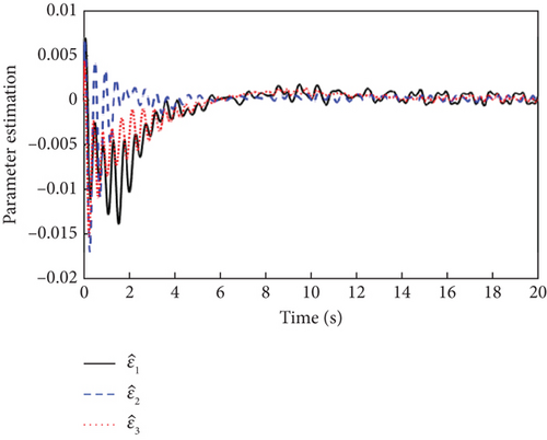
It can be seen from Figure 5 that both the L1 adaptive controller and the MRAC controller have good attitude tracking performance even under the effect of sensor faults. Compared with the MRAC controller, the proposed L1 adaptive controller has the advantages of low overshoot, fast response, and convergence, which has better dynamic performance. As can be seen from Figure 6, the output signals of the inner and outer loop controllers fluctuate more than that without fault due to the existence of sensor faults. From the response curves of parameter estimation in Figure 7, it can be seen that all the adaptive parameters maintain boundedness and fast convergence even in the case of sensor fault.
5.3. Scenario 3: Actuator Faults
The actuator faults are designed as ω = diag(0.3, 0.5, 0.2t).
It shows that the aileron and elevator channels have constant multiplicative actuator faults, while the rudder channel has time-varying multiplicative actuator faults. The simulation results are shown in Figures 8, 9, and 10.
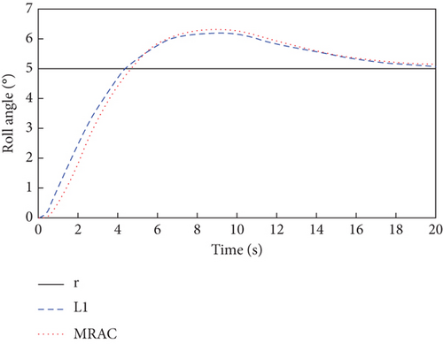
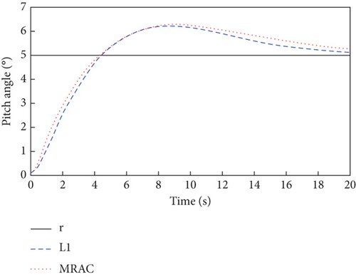
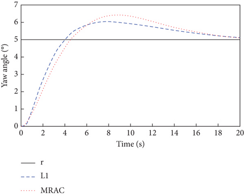
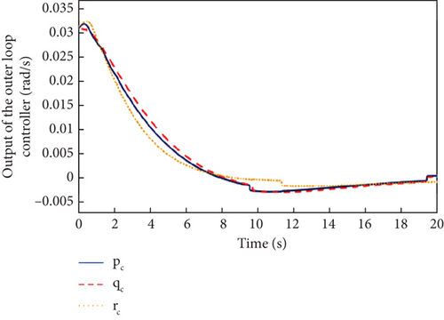
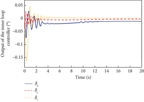
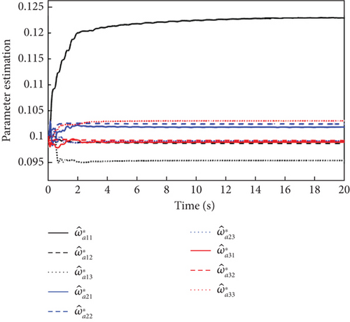
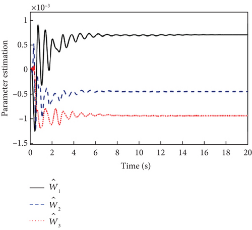
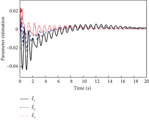
As can be seen in Figure 8, due to the presence of actuator faults, the closed-loop system has a greater overshoot compared to when there are no faults in Figure 2. However, with the inner and outer loop controllers of Figure 9, the three attitude angles are close to a given reference value with fast convergence and small steady-state error. It is also clear from Figure 8 that the proposed L1 adaptive controller has better attitude tracking performance compared to the MRAC controller. Meanwhile, the outputs of the inner and outer loop controllers in Figure 9 and the estimation curves of adaptive parameters in Figure 10 show that the L1 adaptive controller has good stability and fault tolerance.
5.4. Scenario 4: Actuator Faults and Sensor Faults
Obviously, the actuator works normally when t < 8. However, the multiplicative and additive actuator faults are introduced at t = 8. The sensor works normally when t < 7 and the constant offset sensor faults occur at t = 7. The simulation results are shown in Figures 11, 12, and 13.

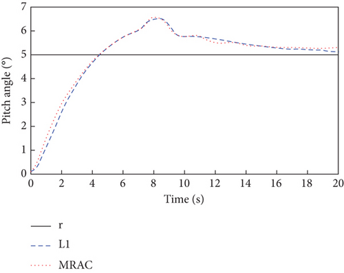
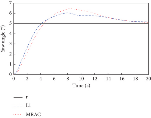

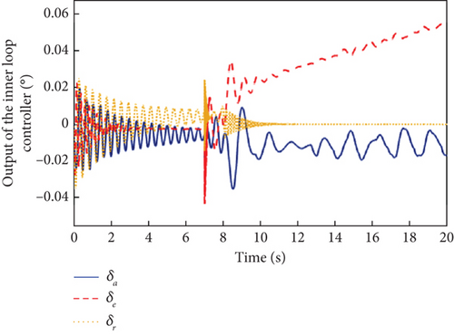
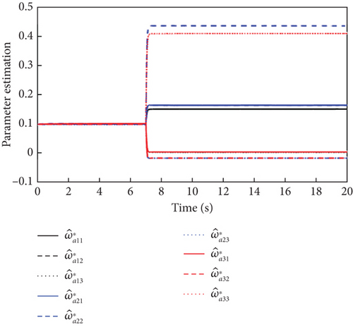

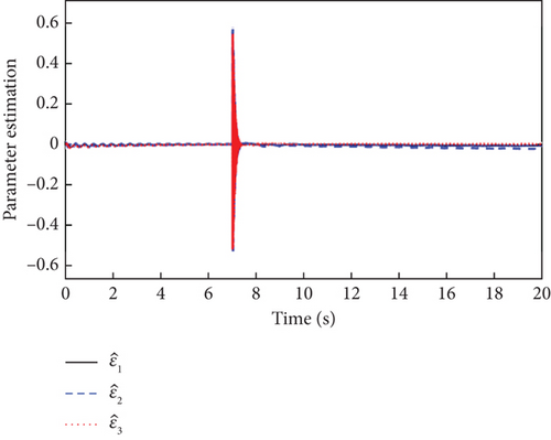
From Figure 11, it is obvious that due to the need for the controller to compensate for the effects of actuator faults and sensor faults, the output signals of the attitude angles are significantly more overshooting than in the case of a single fault mode with sensor faults or actuator faults in Figures 5 and 8. Moreover, the attitude angle tracking curves of the L1 adaptive controller possess a smaller overshoot, faster convergence, and smaller steady-state error than that of the MRAC controller. It can be seen from Figures 12 and 13 that the simultaneous occurrence of actuator faults and sensor faults makes the L1 adaptive controller’s output signals and the estimation curves of the adaptive parameters oscillate more significantly compared to a single fault mode of sensor faults or actuator faults in Figures 6, 7, 9, and 10. Nevertheless, it can be seen from Figures 2, 3, 4, 5, 6, 7, 8, 9, 10, 11, 12, and 13 that the L1 adaptive controller has good attitude tracking ability, strong robustness, and fault tolerance.
6. Conclusion
This paper explored a dual-loop fault-tolerant control for a UAV attitude tracking system in the presence of multiple faults, input saturation, and external disturbances. The outer loop controller adopted a NDI algorithm based on integral sliding mode control, which was used to ensure the fast response and improve the robustness. Input saturation was converted into system uncertainties and disturbances by means of function approximation and the median theorem. With the method of state-variable expansion, multiple faults including actuator faults and sensor faults are treated as a single actuator fault. On this basis, the L1 adaptive control based on RBFNN could be applied to the inner loop to counteract the effects of uncertainties. Simulation results showed that the dual-loop fault-tolerant controller achieved good attitude tracking and guaranteed uniform boundedness of all input and output signals. Next, other adaptive fault-tolerant control methods for multiple faults and input saturation will be a future research direction, such as antisaturation controllers and fault estimators.
Conflicts of Interest
The authors declare no conflicts of interest.
Funding
This work was supported by key fields special project of Guangdong Provincial Colleges and Universities under Grant 2021ZDZX1082.
Acknowledgments
This work was supported by key fields special project of Guangdong Provincial Colleges and Universities under Grant 2021ZDZX1082.
Open Research
Data Availability Statement
The data (system parameters and simulation parameters) used to support the findings of this study are included within the article.


