Synthesis of Stable and Efficient Electrocatalysts for Hydrogen Evolution: Hierarchical NiMo-Based Hollow Nanotubes
Abstract
Large-scale development of low-cost, efficient, and stable powder electrocatalysts for the hydrogen evolution reaction (HER) in alkaline solutions is a key step toward commercial hydrogen production. Herein, a hierarchical NiMo-MoO3-x hollow nanotube (NiMo-MoO3-x-HNT) with bifunctional groups as an efficient HER electrocatalyst was strategically invented using an MoO3 nanorod (MoO3−NR) as the precursor. The synthesis mechanism of the NiMo-MoO3-x-HNT is established based on in-depth investigations using diffraction, spectral, and microscopy results. Experimental results suggest that the NiMo-MoO3-x-HNT exhibits excellent electrocatalytic HER performance in 1 M KOH, with a low overpotential of 26.5 [email protected] mA cm-2 and a small Tafel slope of 32.6 mV dec–1. These values are comparable to those of cutting-edge electrocatalysts based on platinum-group metals. Moreover, it exhibits an almost unaffected cyclic stability over 50,000 cycles and robust durability over 98 h. This remarkable performance is attributed to its bifunctional groups and the porous hierarchical hollow nanotubular morphology. In summary, this study proposes a novel, efficient, and cost-effective strategy for the development of noble metal-free, high-performance HER electrocatalysts.
1. Introduction
Hydrogen is considered a future energy carrier that can replace traditional fossil fuels [1, 2]. To meet global demands, electrochemical water splitting is considered the most efficient method for the production of clean hydrogen [3–6]. In the industry, hydrogen is produced by water electrolysis in an alkaline medium because of its ecofriendliness and economic viability [7]. For water splitting in an alkaline solution, platinum group metals (PGMs: Pt and Ru), especially Pt, are highly efficient electrocatalysts for hydrogen evolution reaction (HER) with very low overpotential; however, their high cost and scarcity restrict their large-scale application [8]. An ideal HER electrocatalyst should have low overpotential and long durability, and its bulk production should be economically feasible. Consequently, the development of an efficient earth-abundant HER electrocatalyst in an alkaline solution is crucial for replacing PGM-based catalysts in large-scale applications [9, 10].
Tremendous efforts have been made on non-PGMs (including Ni, Co, Mo, and Fe) and their compounds, such as alloys and oxides, for use as potent water-splitting catalysts [11–17]. After Pt/C, alloys such as PtCo, RuCo, RuNi, and NiMo are among the most promising candidates for HER [5, 18–20]. Alloys have been shown to enhance HER catalytic activity by fine-tuning the binding energy of hydrogen on the catalyst surface [21]. In particular, the NiMo alloy has exhibited immense potential as an alkaline HER electrocatalyst because of its cost-effectiveness and unique properties. NiMo has an electronic surface state similar to that of platinum [11–13] and induces a synergistic effect through electron transfer from electron-rich Ni to electron-deficient Mo [22]. Several approaches have been suggested for the design of the NiMo alloy-based HER electrocatalysts in powder form, and overpotential ≥ 65 mV and Tafel slope ≥ 36.6 mV dec-1 have been achieved [3, 5, 11, 23, 24]. Therefore, the development of a high-performance powder electrocatalyst based on NiMo alloy is one of the potential candidates to substitute Pt/C.
The performance of the NiMo alloy can be improved using several approaches, such as tuning the electronic structure/chemical composition and synthesizing well-organized porous morphologies. Typically, two critical reactions occur on the catalyst surface during molecular H2 production from water: cleavage of the H–OH bond to its intermediates and conversion of the intermediates to H2. Several studies have demonstrated that metal oxides are effective in cleaving the H–OH bond, whereas metals with optimal M-Had energies play a crucial role in converting the intermediates to H2 [25]. Therefore, metal-metal oxide heterostructures can accelerate the overall HER performance. Recently, some metal-metal oxide-based heterostructures (Pt-Ni(OH)2, Ru-O-Mo, and MoNi-Ni(OH)2) have been reported to demonstrate bifunctional effects in improving the catalytic behavior of HER [26–29]. Further, the intrinsic activity of electrocatalysts can be tuned using several approaches, including tuning electronic conductivity, controlling the dimensions of nanostructured materials (0 to 3 D), and creating porous/hollow/hierarchical structures [14, 15, 30–33]. Typical hierarchical hollow nanotubular structured materials represent a novel class of materials with unique structural dimensions [16, 17, 34–38]. The 1D core hollow nanotube (HNT) provides an easier charge-transport network with reduced scattering, facilitates rapid mass transport, and maintains electrolyte accessibility through its hollow tunnel [39], whereas the hierarchical 2D surface provides a large effective catalytic surface area, which prevents particle aggregation and accelerates the release of H2 bubbles [40]. Thus, electrocatalysts featuring hierarchical hollow nanotube structures with metal-metal oxide heterostructures can demonstrate excellent HER performance.
Motivated by this concept, a porous hierarchical NiMo-MoO3-x-HNT electrocatalyst with bifunctional groups (NiMo alloy and MoO3-x oxide) was developed for the HER. The hollow nanotube with a hierarchical 2D surface, consisting of metal-metal oxide, was prepared through a hydrothermal process followed by a thermal reduction process utilizing MoO3 nanorods as a one-dimensional template to induce Kirkendall voids. To optimize the synthesis process of NiMo-MoO3-x-HNT, the electrocatalysts and intermediate products were characterized using various techniques, including diffraction, spectroscopy, and microscopy. The electrocatalytic HER performance of the catalysts was investigated in a 1 M KOH solution using various electrochemical techniques. The prepared catalyst exhibited favorable attributes, including a high surface area, porosity, and effective synergy between NiMo alloy and MoO3-x components, making it a promising candidate for electrocatalytic applications, particularly in the context of HER. Furthermore, a study on the catalyst’s durability after a cycle life test was conducted, and its electrochemical activity, morphological changes, and chemical states were analyzed.
2. Experimental Section
2.1. Materials
Ammonium heptamolybdate (Sigma-Aldrich, purity 99.0%), nickel acetate tetrahydrate (purity 99.98%, Sigma-Aldrich), potassium hydroxide (Sigma-Aldrich, purity ≥ 85%), nitric acid (purity 64–66%, Duksan Reagents), and Pt/C (Johnson-Matthey, 40 wt%) were used as-received.
2.2. Synthesis of MoO3 Nanorod
Ammonium heptamolybdate (1.0 g) was dissolved in 33.4 mL of deionized water. After complete dissolution, 6.6 mL of HNO3 was added dropwise to this solution under constant stirring. The solution was transferred to a Teflon-lined autoclave (50 mL) and hydrothermally treated at 180°C for 20 h in an electric oven [41]. The reactor was allowed to cool naturally to room temperature after the completion of the reaction. The resulting MoO3 nanorod (MoO3-NR) was filtered, washed with water and ethanol, and dried overnight at 60°C.
2.3. Synthesis of Hierarchical NiMoO4-Ni(OH)2 Hollow Nanotube
In this study, MoO3-NR (0.1 g) was dispersed in 20 mL of deionized water and sonicated for a few minutes, after which it remained dispersed for a long time. Subsequently, nickel acetate (0.99 gm, 0.1 M) was added to the MoO3-NR dispersion, which resulted in instant precipitation. The precipitate was sonicated and stirred for a few minutes. Next, 20 mL of ethanol was added, and the solution was stirred for another 15 min. Thereafter, the solution was transferred to a Teflon-lined autoclave and heat-treated in an electric oven for 5 h at 90°C. The reactor was allowed to cool naturally to room temperature after the completion of the reaction. The product, designated as NiMoO4-Ni(OH)2 hollow nanotube (NiMoO4-Ni(OH)2-HNT), was collected by filtration and was washed with water and ethanol before drying overnight at 60°C.
2.4. Synthesis of Hierarchical NiMo-MoO3-x Hollow Nanotube
The targeted hierarchical NiMo-MoO3-x hollow nanotube (NiMo-MoO3-x-HNT) catalyst was prepared by thermal reduction of the NiMoO4-Ni(OH)2-HNT (0.2 g) at 500°C in a tube furnace for 2 h at a heating rate of 10°C/min in an Ar/H2 (90/10, V/V) atmosphere. The influence of the reduction temperature was also explored through the synthesis of catalysts at different temperatures, spanning from 400 to 800°C. The prepared electrocatalysts were designated as Ni-Mo–x, where x indicated the reduction temperature.
3. Structural Characterization
Powder crystallographic patterns of the specimens were obtained using a Rigaku MiniFlex X-ray diffractometer with CuK radiation in the scan range of 10–80° (2θ). Their powder morphology images were captured using a field-emission scanning electron microscope (FE-SEM, JEOL-7800F). JEM-F200 was used to capture transmission electron microscopy (TEM) images and perform electrochemical dispersive spectroscopy (EDS). The mass percentages of the elements in the specimens were determined using inductively coupled plasma optical emission spectrometry (ICP-OES, Thermo Scientific iCAP-6000) by dissolving the specimens in an acid. Surface area and pore size distribution curves were acquired using an Autosorb-iQ 2ST/MP system (Quantachrome Instruments). The chemical states of the specimens were analyzed by X-ray photoelectron spectroscopy (XPS, K-alpha, Thermo VG).
4. Electrochemical Measurements
All the electrochemical measurements were performed using a Biologic VSP electrochemical workstation with a standard three-electrode system. The catalyst ink was formulated by subjecting 10 mg of the catalyst, 1 mL of isopropanol, and 75 μL of Nafion to sonication for 1 hour. Once a uniform catalyst ink was achieved, 50 μL of this ink was applied via drop-coating onto a rotating ring disk electrode (RRDE) measuring 5.6 mm in diameter and possessing a surface area of 0.247 cm2. The electrochemical HER performance of the catalyst was determined using the catalyst-loaded RRDE as the working electrode, Hg/HgO as the reference electrode, and a graphite rod as the counter electrode, all immersed in a 1 M KOH solution. To convert the potential scale to a reversible hydrogen electrode (RHE), an adjustment of 0.922 V was made. This value was determined through the calibration of the Hg/HgO electrode by introducing H2 gas into a 1 M KOH solution, with two Pt wires serving as the counter and working electrodes separately. The catalyst was activated through the five cycles of cyclic voltammetry (CV) at a scan rate of 1 mV s–1, covering a potential range from 0.1 to −0.5 V versus the RHE. All linear sweep voltammetry (LSV) profiles were captured at a rotation speed of 2500 rpm and a scan rate of 5 mV s–1. Catalyst stability was evaluated using CV at a sweep rate of 200 mV s–1 over a potential range of 0.2 to −0.25 V versus RHE for 50,000 cycles. Further, the durability of the optimized catalyst was investigated using the chronopotentiometric (CP) method at a current density of 10 mA cm–2 for 98 h. The IR correction for all LSV curves was performed by calculating EIR (EIR-corrected potential) using the formula EIR = EM − I × RS, where EM represents the measured potential and RS is the electrode resistance determined through electrochemical impedance spectroscopy in 1 M KOH.
5. Results and Discussion
5.1. Synthesis and Characterization

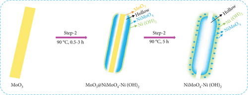
Finally, in step 3, when the NiMoO4-Ni(OH)2-HNT was annealed at 500°C under a reduction atmosphere (Ar/H2), it was converted to a hierarchical NiMo-MoO3-x hollow nanotube through the elimination of the maximum possible amount of oxygen and water.
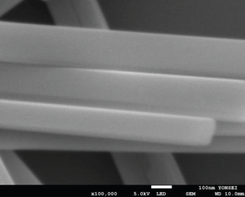
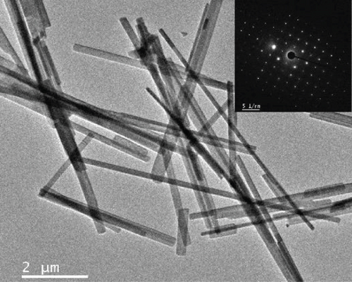
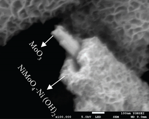
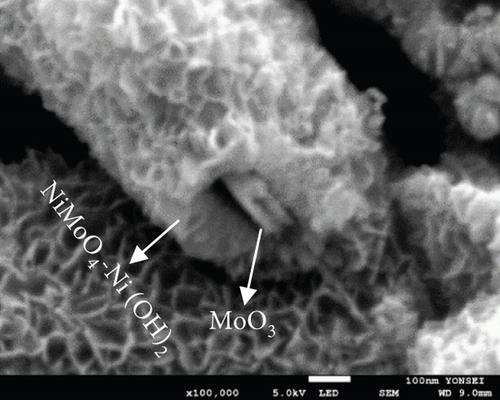
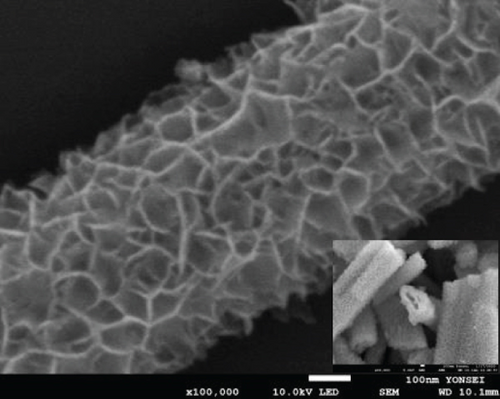
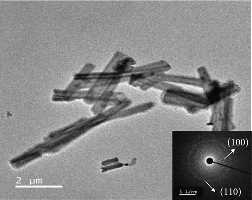
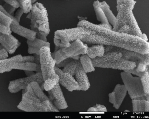
The morphologies of the prepared samples were investigated using FE-SEM and TEM. The MoO3-NR exhibited a solid nanorod-like morphology, with a diameter and length of approximately 200 nm and 5–10 μm, respectively, as confirmed by FE-SEM (Figure 2(a)) and TEM images (Figure 2(b)). Furthermore, the selected area electron diffraction (SAED) pattern of the MoO3-NR (inset of Figure 2(b)) revealed ordered lines, indicating its single-crystalline nature. Figures 2(c)–2(e) provide valuable insights into how the growth process of NiMoO4-Ni(OH)2-HNT is influenced by the reaction time. As the hydrothermal reaction time was increased from 0.5 h to 5 h in step 2, the MoO3-NR core gradually decreased and eventually disappeared after 5 h. As the reaction time progressed, the MoO3 core underwent a comprehensive conversion into NiMoO4 and/or experienced erosion through etching, facilitated by its heightened water solubility at elevated temperatures. Concurrently, the thickness of Ni(OH)2 on the MoO3-NR surface increased proportionally with reaction time, as evidenced by the X-ray diffraction (XRD) analysis and detailed in subsequent sections. Collectively, these factors led to the emergence of well-defined hollow nanotubes, contributing to the formation of the NiMoO4-Ni(OH)2-HNT structures, as illustrated in Figure 2(g). A reaction time of 5 h was required to consistently generate uniform nanotubular structures. The FE-SEM (Figure 2(e)) and TEM (Figure 2(f)) images of the NiMoO4-Ni(OH)2-HNT exhibited a hollow nanotube morphology with a shell composed of hierarchical 2D nanosheets. The SAED pattern (inset of Figure 2(f)) of the nanosheets present in the shell showed two diffraction rings, identified as the (100) and (110) planes of Ni(OH)2. The diameter and length of the NiMoO4-Ni(OH)2-HNT were in the ranges of approximately 200–500 nm and 1–5 μm, respectively. The shorter length of the NiMoO4-Ni(OH)2-HNT compared with that of the MoO3-NR precursor may be attributed to the etching/solubility of the MoO3-NR at elevated temperatures.
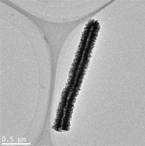
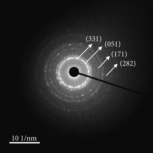
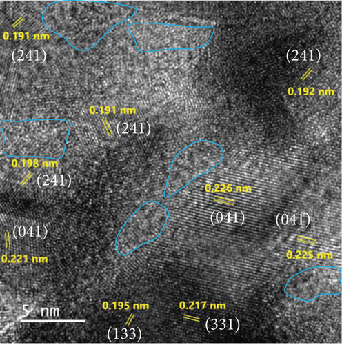
The FE-SEM (Figure 3(a)) and TEM (Figure 3(b)) images of the targeted NiMo-MoO3-x-HNT indicated that its morphology was identical to that of the precursor. Thus, the hollow nanotube structure of the catalyst consists of hierarchical 2D nanosheets, which provide a large effective catalytic surface area for the HER. The SAED pattern of the NiMo-MoO3-x-HNT (Figure 3(c)) exhibited four diffraction rings, identified as the (331), (051), (171), and (282) planes of the NiMo alloy. The EDAX mapping images of the NiMo-MoO3-x-HNT (Figure S2) indicate that Ni, Mo, and O are uniformly distributed throughout the HNT. The presence of O in the NiMo-MoO3-x-HNT may be attributed to the presence of the MoO3-x functional group of the catalyst and the formation of a thin oxide layer on the alloy surface owing to the sensitivity of the alloy to air. The MoO3-x in the NiMo-MoO3-HNT exists in an amorphous state, as indicated by blue circles in the HR-TEM image (Figure 3(d)). The area outside the blue circle represents the NiMo-distinctive alloy characteristics, as indicated by the d-spacing (0.19, 0.20, 0.21, and 0.22 nm) fringes (Figure 3(d)), confirming the development of bifunctional groups in the NiMo-MoO3-x-HNT catalyst. The structural changes in the catalysts synthesized at various reducing temperatures in step 3 were investigated using FE-SEM (Figure S3). When the annealing temperature was increased to 600°C, the morphological integrity of the prepared alloys started to agglomerate, and the size was reduced because of the thermal reduction process. Above 700°C, the morphological integrity of the prepared alloys was destroyed, and they were compressed to a denser state, where there were no hierarchical nanosheet units were present. Therefore, in order to maintain the shape of the nanotube, it is necessary to maintain the thermal reduction temperature below 500°C.
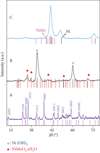
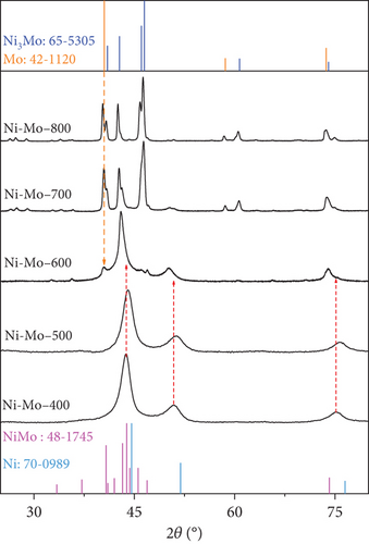
Crystal structures of the prepared materials were investigated using XRD and are presented in Figure 4. The diffraction pattern of the MoO3-NR, as shown in Figure 4(a) (A), perfectly matched with the crystal peaks of α-MoO3 (JCPDS no. 35-0609). The diffraction pattern of the NiMoO4-Ni(OH)2-HNT (Figure 4(a)) (B) consisted of NiMoO4 (JCPDS no. 13-0128) and Ni(OH)2 (JCPDS no. 01-1047) crystal peaks, indicating the formation of a NiMoO4-Ni(OH)2-HNT structure. The Ni(OH)2 crystal peaks were predominant because they were present on the outer surface of the NiMoO4-Ni(OH)2-HNT. Furthermore, the hydrothermal reaction time-dependent crystal growth of the NiMoO4-Ni(OH)2-HNT was investigated by measuring the XRD patterns at different time intervals, as shown in Figure S4. When the hydrothermal reaction time at step 2 was increased from 0.5 h to 10 h (step 2), the peak of MoO3 steadily decreased and disappeared, whereas the peak of Ni(OH)2 strengthened and NiMoO4 appeared. This coincides with the result depicted in Figure 2, which shows that as the hydrothermal reaction progresses, MoO3 disappears, creating a void in the nanotube, and the thickness of Ni(OH)2 gradually increases on the surface. The diffraction pattern of the targeted NiMo-MoO3-x-HNT (Ni-Mo-500) catalyst (Figure 4(a)) (C) comprised a mixture of the Ni fcc phase (JCPDS no. 70-0989) with a slight shift and the NiMo-phase (JCPDS no. 48-1745), which was consistent with the previously reported Ni2Mo-alloy pattern [45]. The XRD patterns of the catalysts synthesized at various reducing temperatures (400–800°C) at step 3 are shown in Figure 4(b). The XRD pattern of the Ni-Mo-400 catalyst was almost identical to that of the Ni-Mo-500 catalyst, although the crystal peaks of Ni-Mo-500 were positively shifted by 0.32° in comparison with those of Ni-Mo-400, possibly because of the effective synergy between Ni and Mo in Ni-Mo-500. For the Ni-Mo-600 catalyst, a new XRD peak appeared at 2θ = 40.4° for the (110) plane of Mo (JCPDS no. 01-1207), and its crystal peaks were negatively shifted by 1.07° relative to the Ni-Mo-500 peaks. This result indicated that the Mo metal was slightly separated from the alloy, thereby weakening the synergy between Ni and Mo. When the temperature was increased from 600°C to 700 and 800°C, the XRD patterns comprised a mixture of prominent Mo-metal and Ni3Mo-alloy (JCPDS no. 65-5305) phases. This finding indicates that at higher temperatures, the catalyst decomposes into Ni3Mo-alloy and Mo-metal. Consequently, the XRD analysis suggests that Ni-Mo-500 has the highest synergy between Ni and Mo.
The compositions and electronic structures of the prepared catalysts and their precursors were investigated using XPS, as shown in Figure 5 and Figure S5, respectively. The Ni-2p core-level spectrum of the NiMoO4-Ni(OH)2-HNT (Figure 5(a)) exhibited Ni2+-2p3/2 and Ni2+-2p1/2 peaks at binding energies (BE) of approximately 855.9 and 873.5 eV, respectively, with a separation of 17.7 eV [46]. As evidenced in Figure 5(b), the NiMo-MoO3-x-HNT electrocatalyst exhibited two main peaks at 852.8 and 870.0 eV, corresponding to the Ni0-2p3/2 and Ni0-2p1/2 electrons, revealing the almost complete transition of the Ni2+ state into the metallic Ni0 state. The higher binding energy of Ni0-2p3/2 in the NiMo-MoO3-x-HNT electrocatalyst compared with that of the pure Ni metal (the binding energy of Ni0-2p3/2 in pure Ni metal is 852.6 eV) demonstrated the existence of the alloy state [47]. The presence of small humps at BEs of approximately 855.9 and 873.5 eV in the NiMo-MoO3-x-HNT electrocatalyst (Figure 5(b)), corresponding to the Ni2+-2p3/2 and Ni2+-2p1/2 electrons, may be explained by surface oxidation in the presence of air [48].
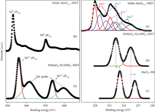
For the Mo-3d analysis, a significantly lower Mo-3d binding energy shift in the NiMoO4-Ni(OH)2-HNT (Mo6+-3d5/2 with BE of 232.34 eV) compared with that in the MoO3-NR (Mo6+-3d5/2 with BE of 233.1 eV) precursor (Figure 5(d)) indicated the successful transformation of MoO3 into NiMoO4. The deconvoluted Mo-3d XPS peak of the NiMo-MoO3-x-HNT (Figure 5(e)) revealed eight distinct peaks. Among these, two peaks corresponded to the metallic Mo0 state, whereas the remaining six peaks indicated various oxide states (Mo4+, Mo5+, and Mo6+: MoO3-x, where 0 < x < 1) [5]. Surprisingly, despite the electron transfer from Ni to Mo in the Ni-Mo-500 electrocatalyst, a positive shift was observed in the BE of the Mo0 state (228.17 eV) compared with that of the pure Mo metal (227.85 eV). This finding suggests electron transfer from Mo0 to MoO3-x, implying the presence of a NiMo-MoO3-x bifunctional structure with synergy between the NiMo alloy and MoO3-x. Furthermore, within the NiMo-MoO3-x-HNT, the Mo6+ state displayed a notably reduced BE of 231.91 eV, in contrast to the MoO3-NR (233.1 eV) as well as the NiMoO4-Ni(OH)2-HNT (232.34 eV). Similarly, the state in the NiMo-MoO3-x-HNT exhibited a lower binding energy (Mo4+-3d5/2 with a BE of 229.24 eV) compared with that of the pure MoO2 (Mo4+-3d5/2 with a BE of 229.9 eV). These observations suggest an electron transport mechanism from Ni0 to Mo0 and subsequently from Mo0 to molybdenum oxide. In essence, the NiMo-MoO3-x-HNT predominantly consists of Ni0 and Mo0 metallic states as NiMo alloys, along with some MoO3-x phase. This arrangement highlights the development of a NiMo-MoO3-x bifunctional group structure, emphasizing substantial synergy between the alloy and oxide constituents. An ICP-OES analysis (Table S1) showed an Ni : Mo atomic ratio of approximately 2.5 : 1 in the NiMo-MoO3-x-HNT catalyst, suggesting that the exact chemical composition is Ni2.5Mo1-y-yMoO3-x (0 < y < <1).
Furthermore, XPS analysis was employed to examine the influence of reducing temperatures on the chemical states, chemical composition, and synergistic properties of the prepared catalysts (Figure S5). The catalysts prepared at 400°C showed oxide (Ni2+, Mo4+, and Mo6+) and alloy (Ni0 and Mo0) peaks, indicative of the incomplete reduction of the precursor. The catalysts prepared at ≥600°C exhibited primarily alloy peaks with only a trace of oxide peaks. In addition, a significant negative shift was observed in the BE of Mo0 because of the decrease in the MoO3-x content and splitting of the Mo metal; thus, there may be less synergy between the alloy and oxide contents, as well as between Ni and Mo, compared with that of Ni-Mo-500. Based on the XPS analysis, the effective interaction between Ni, Mo, and MoO3-x occurred when the catalyst was prepared at 500°C. Therefore, the chemical composition of the catalysts can be tuned by adjusting the reduction annealing temperature, which can affect the catalytic activities.
The chemical compositions of the prepared catalysts were assessed using Fourier-transform infrared spectroscopy, as shown in Figure S6. The prepared MoO3-NR exhibited peaks at 545 (bending vibration of Mo3-O), 875 (stretching vibration of Mo2-O), and 997 cm–1 (asymmetric stretching of Mo=O), confirming the formation of MoO3 [49]. The NiMoO4-Ni(OH)2-HNT exhibited peaks at 480 (Ni-O building group in NiMoO4/Ni(OH)2), 750 (symmetric stretching of Mo-O-Ni), 820 (asymmetric stretching of Mo2-O), 864 (asymmetric stretching of Mo=O), and 925 cm–1 (symmetric stretching of Mo2-O), evidencing the characteristic peaks of NiMoO4 and Ni(OH)2 and formation of the NiMoO4-Ni(OH)2-HNT. In addition, the IR peaks of MoO3-NR almost vanished/shifted in the NiMoO4-Ni(OH)2-HNT, indicating the transition of MoO3-NR to NiMoO4, which is consistent with the XRD and XPS results. The Ni-Mo-400, which exhibited the characteristic peaks of its precursor, proved that the precursor was incompletely reduced in the NiMo alloy. However, the intensity of the oxide peaks in Ni-Mo-500 was lower than in Ni-Mo-400, indicating that Ni-Mo-500 contained a minimal amount of oxide content (733 cm-1 of Mo-O-Ni, 845 cm-1 of Mo2-O, and 925 cm-1 of Mo = O), which enabled the development of the NiMo-MoO3-x-HNT. In contrast, the NiMo alloy produced at ≥600°C showed no oxide peaks, suggesting the maximal transition of the precursor oxide into the alloy.
The N2 adsorption–desorption measurements were performed to investigate the BET surface area and porosity of the NiMoO4-Ni(OH)2-HNT and Ni-Mo-500 (Figure S7). The isotherms can be classified as type IV patterns in the presence of H3-type hysteresis loops, indicating their porous structures. The NiMoO4-Ni(OH)2-HNT exhibited a high specific surface area and pore volume of 274.3 m2 g–1 and 0.46 cm3 g–1, respectively, due to the hierarchical HNT structure. After undergoing reduction heat treatment at 500°C, NiMo-MoO3-x-HNT showed reduced values of 82.5 m2 g–1 and 0.25 cm3 g–1 due to the formation of the alloy resulting from the removal of oxygen during the thermal reduction process. As the reducing temperature was increased further, as shown in Figure S8, the surface area and pore volume of the NiMo alloys decreased to 26.4 m2 g–1 and 0.11 cm3 g–1, respectively, leading to the collapse and shrinkage of the HNT structure, as confirmed in Figure S3. Thus, the optimized NiMo-MoO3-x-HNT electrocatalyst prepared at 500°C is a metal alloy-oxide bifunctional group with synergy between the alloy and oxide components. Furthermore, it has a porous hierarchical hollow nanotubular morphology with an optimal surface area, which are ideal features for an HER electrocatalyst.
5.2. Electrocatalytic Hydrogen Evolution Performance of NiMo-MoO3-x-HNT
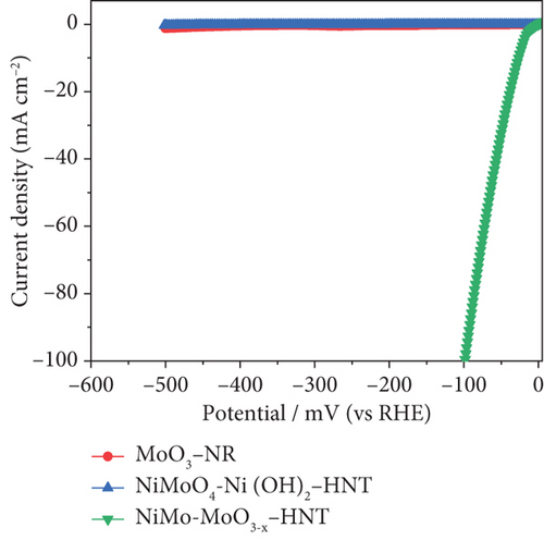
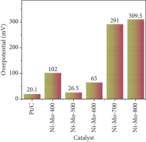
The electrocatalytic HER performances of the prepared catalysts and their precursors were assessed based on their polarization curves (I-V plots) at a sweep rate of 5 mV s–1, as illustrated in Figure 6. As shown in Figure 6(a), the electrocatalytic HER activity of the catalysts followed the order Ni-Mo-800 < Ni-Mo-700 < Ni-Mo-400 < Ni-Mo-600 < Ni-Mo-500, whereas the precursors showed negligible performance (Figure 6(b)). The HER performance of the NiMo-MoO3-x-HNT (Ni-Mo-500) was outstanding, requiring only an overpotential of 26.5 mV to generate a current density of 10 mA cm–2, which was closer to that of Pt/C (20.1 mV).
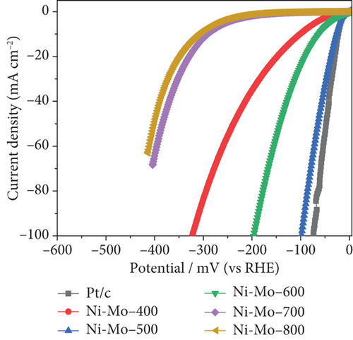
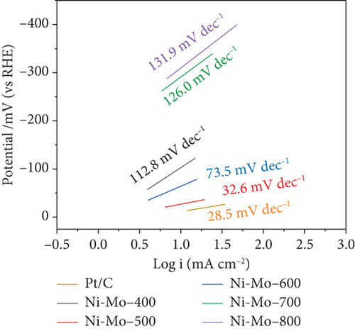
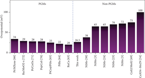
The low Tafel slope value of only 32.6 mV dec–1 for the Ni-Mo-500 catalyst indicated that the HER followed the faster Volmer–Tafel model, and the chemical desorption of hydrogen, i.e., the Tafel step, was the corresponding rate-determining step [65, 67, 68].
- (1)
Bifunctional properties of metal-metal oxide. Our recent DFT simulation study explained the bifunctional properties of NiMo alloy and MoO3-x [73]. In NiMo alloy systems, electrons transfer from the electron-rich Ni to the electron-deficient Mo, resulting in Mo acting as a site that adsorbs H2O molecules [74]. When MoO3-x is introduced into the NiMo alloy, the adsorption-free energy of H2O on the Mo center becomes more negative, indicating a preference for H2O adsorption. This strong H2O adsorption on the Mo center of NiMo˗MoO3-x lowers the energy barrier of O-H bond cleavage, further accelerating the H2 production rate. After O-H dissociation, OH remains at the Mo center, while H shifts to the Ni center, leading to subsequent H2 evolution. The Ni center is preferred for H2 evolution over the Mo center due to the lower hydrogen adsorption energy. DFT analysis demonstrated that, compared to the NiMo alloy, the Ni center of NiMo-MoO3-x exhibited an adsorption-free energy of H∗ closer to zero, indicating facilitation of the HER reaction
- (2)
Morphological advantages. The porous hierarchical hollow nanotubular morphology of the NiMo-MoO3-x-HNT provides a large catalytic surface area for the HER. The core 1D tubular structure facilitated rapid charge transport during electrolysis, and the porous hollow morphology sustained the accessibility of the electrolyte
To assess the intrinsic activity of NiMo-MoO3-x-HNT, the turnover frequency (TOF) per active site of the catalyst in the HER process was determined, as outlined in the supporting information. The TOF of Ni-Mo-500 catalyst with a loading of 1.88 mg cm-2 is determined to be 0.1307 H2 molecules s–1 at an overpotential of 100 mV, which is higher than those of reported HER catalysts, such as 0.1 mg cm-2 loaded Ni-Mo alloy (0.05 H2 molecules s–1), 1.6 mg cm-2 loaded NiMoFe alloy (0.05 H2 molecules s–1), and ~1.0 mg cm-2 loaded Ni2P nanoparticles (0.012 H2 molecules s–1) [23, 75, 76]. Impedance analysis was utilized to examine the charge-transfer kinetics of the prepared catalysts. For a more comprehensive analysis, Nyquist plots were fitted with an equivalent circuit consisting of electrolyte resistance, charge transfer resistance, and constant phase element [77]. As illustrated in Figure S9, NiMo-MoO3-x-HNT, characterized by the smallest semicircle, exhibited the lowest charge-transfer resistance among all the prepared catalysts, even comparable to Pt/C (Figure S9c). The electrochemical double layer capacitance (Cdl) of a catalyst is a significant characteristic for evaluating its electrochemical active surface area (ECSA and ECSAαCdl) and intrinsic catalytic activity. Among all the prepared Ni-Mo alloys (Figure S10), the NiMo-MoO3-x-HNT catalyst exhibited the maximum Cdl of 121 mF cm-2, indicating that its greater ECSA contributed to its strong catalytic activity. The higher Cdl of the NiMo-MoO3-x-HNT catalyst is attributed to its hierarchical nanotubular morphology with a high surface area and the optimal composition of its alloy and oxide particles.
5.3. Cycle Life Stability and Durability of NiMo-MoO3-x-HNT
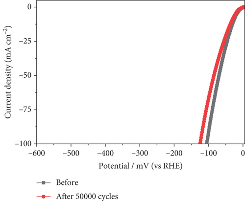
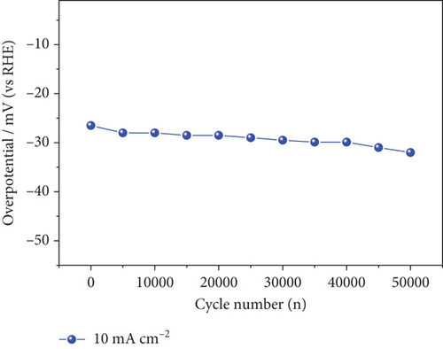
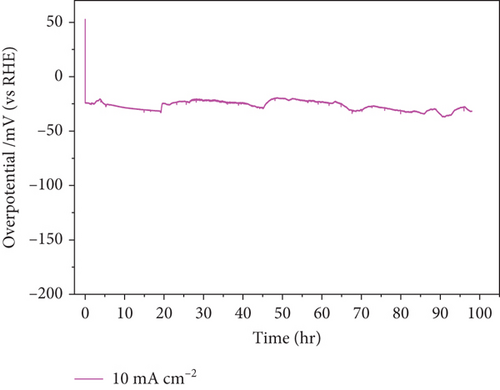
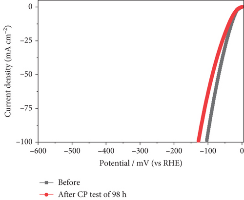
In addition to electrocatalytic activity, the stability of a catalyst is an important consideration when evaluating it for industrial hydrogen production. The stability of the NiMo-MoO3-x-HNT (Ni-Mo-500) was investigated using CV measurements, as shown in Figure 7(a). After 50,000 cycles of operation, the NiMo-MoO3-x-HNT almost retained current density and overpotential (changed from 26.5 mV to 32 mV, Figure 7(b)), demonstrating its outstanding stability. Furthermore, the durability of the NiMo-MoO3-x-HNT was investigated using the CP method at 10 mA cm–2 for 98 h (Figure 7(c)). The NiMo-MoO3-x-HNT showed excellent durability, exhibiting an almost unchanged overpotential (Figure 7(d)) after 98 h of hydrogen production. The morphological investigation of the NiMo-MoO3-x-HNT after the cycle test indicated that its hierarchical hollow nanotubular structure was well preserved even after 50,000 cycles (Figure S11), which ensured its catalytic durability for the HER and its structural stability. In addition, the EDAX mapping analysis detected Ni, Mo, K, and O; the retention of Ni and Mo indicated the high chemical stability of the catalyst (Figure S12). The presence of K in the catalyst was due to the KOH electrolyte penetrating and getting trapped inside the core level of the catalyst during the cycle-life analysis.
The examination of chemical states following the cycle life test using XPS is presented in Figure S13. The deconvolution of Ni-2p XPS peaks in NiMo-MoO3-x-HNT revealed the presence of Ni-Had (hydrogen adsorbed in Ni). This occurrence can be attributed to the role of Ni as a center for proton adsorption (H∗), contributing to H2 formation [78, 79]. The observation of the Ni2+ state suggests the formation of nickel oxide due to Ni0 interaction with the KOH electrolyte. The deconvoluted Mo-3d peaks indicate a transformation from the Mo0 to the Mo6+. Mo plays a vital role in accelerating the adsorption of water molecules and the dissociation of H-OH. As a result, during the repeated cycling process, the Mo surface undergoes a transition to a higher oxidation state, which is reflected in the XPS. Notably, the BE of Ni0-2p3/2 and Mo6+-3d5/2 exhibit little change even after cycling, indicating that the catalyst retains its metal-metal oxide synergy effect. As confirmed by EDAX, the presence of K in the catalyst was also observed in XPS after the cycle life test, indicating that the KOH electrolyte had penetrated inside the catalyst (Figure S13b). Overall, the NiMo-MoO3-x-HNT demonstrates good cycle stability and high catalytic activity due to its structural robustness and bifunctional effect. This high catalytic efficiency and long-term stability hold promise for the potential commercialization of cost-effective NiMo-MoO3-x-HNT in the near future.
6. Conclusions
This study demonstrates a novel approach to synthesizing a highly efficient electrocatalyst for the hydrogen evolution reaction based on a NiMo-MoO3-x bifunctional hollow nanotube using MoO3-NR as a 1D template and Mo source. The generation of hierarchical nanotubes was regulated by the hydrothermal reaction time, resulting in the formation of Kirkendall voids at an optimal reaction time of 5 h. The NiMo-MoO3-x-HNT catalyst prepared at an annealing temperature of 500°C emerged as the optimal catalyst, combining a bifunctional metal alloy-oxide structure with a hierarchical hollow nanotubular morphology. This resulted in a favorable surface area and porosity, which are desirable attributes for efficient HER electrocatalysis. The NiMo-MoO3-x catalyst demonstrated efficient HER performance with a low overpotential of 26.5 mV and minimal Tafel slope of 32.6 mV dec−1. Further analysis through impedance measurements validated the efficient charge-transfer kinetics and a substantial electrochemically active surface area. Importantly, the NiMo-MoO3-x catalyst displayed exceptional stability and durability, maintaining a nearly unaltered performance over 50,000 cycles and 98 h of continuous operation. These findings establish the NiMo-MoO3-x catalyst as a viable and prospective alternative to electrocatalysts containing precious metals, particularly for industrial applications.
Conflicts of Interest
The authors declare no interest conflict. They have no known competing financial interests or personal relationships that could have appeared to influence the work reported in this paper.
Acknowledgments
This research was supported by the Basic Science Research Program through the National Research Foundation of Korea (NRF) funded by the Ministry of Education (NRF-2019R1A6A1A11055660 and NRF-2022R1I1A1A01069960) and Strategic Networking & Development Program funded by the Ministry of Science and ICT through the National Research Foundation of Korea (RS-2023-00268523).
Open Research
Data Availability
The data that support the findings of this study are available from the first author upon reasonable request.


