Numerical Simulation of a Gas Burner Using Mixed Propane/Ammonia Fuel
Abstract
In recent years, ammonia has received more and more interest to be used as carbon-free energy. In the present study, a computational model of a burner for the domestic hot water boiler in the building has been developed. The combustion characteristics of propane/ammonia-mixed fuel in the burner were investigated by numerical simulation under different ammonia blending ratios and equivalence ratios. Based on the flue gas concentration distribution of the numerical simulation results, the baseline carbon emission of hot water supply in a community was calculated. The results show that as the ammonia blending ratio increases, the overall combustion temperature decreases. At the outlet of the burner, when the ammonia blending ratio is 0.5, the emission concentration of carbon dioxide can be reduced by 31.4% compared to pure propane combustion. When the ammonia blending ratio increases from 0 to 50%, the carbon baseline emission decreases from 9.89 kg/GJ to 6.87 kg/GJ, and the carbon emission under the baseline decreases from 17.20 T to 11.94 T. The emission of NO pollutants remains basically unchanged due to the decrease of combustion temperature. It indicates that the mixed fuels can effectively reduce carbon emissions in domestic water heaters and have good potential for future application.
1. Introduction
Carbon-based fuels such as natural gas are often used in common domestic water heaters in buildings. Their pollutant and greenhouse gas emissions cannot be underestimated. In the current dual-carbon environment, regulations are being tightened [1–3]. Reducing carbon emissions in buildings and achieving low-carbon requirements are inevitable. As a basic chemical raw material and new fuel, liquefied petroleum gas (LPG) has attracted more and more attention [4]. Liquefied petroleum gas is mainly used as a petrochemical raw material for hydrocarbon cracking with ethylene or steam conversion to synthesis gas [5]. It is widely used in nonferrous metal smelting, automotive fuel, residential life, and other fields. The largest component is propane. However, as a carbonaceous substance, propane still releases carbon dioxide during combustion. Ammonia, as a potential clean energy, has recently attracted extensive research. Previous studies at home and abroad have shown that ammonia is a very competitive clean energy. With the deepening of research on ammonia, it has been found that blending hydrocarbon fuels with ammonia can not only improve the combustion of ammonia but also reduce the greenhouse gas emissions of hydrocarbon fuels. Among a variety of hydrocarbon fuels, propane has the characteristics of density, viscosity, and heat capacity similar to ammonia, so it is relatively easy to realize the blending of ammonia with propane in mixed combustion applications [6].
The use of ammonia fuel for cofiring has been studied for a long time. Yan et al. [7] studied the blow-off and transient characteristics of ammonia/methane fuel cocombustion in swirl combustors. One of the limiting factors for the application of NH3 in combustion systems is its low laminar burning velocity, and the flame stability limit of NH3/air is extremely low. Mei et al. [8, 9] measured the laminar burning velocity of NH3/air-premixed flames at different equivalence ratios using an isometric combustor in the experimental and kinetic simulation study of ammonia laminar flame propagation under oxygen-enriched high-pressure conditions. Han et al. [10, 11] creatively measured the laminar burning velocity of ammonia/air by heat flux method. Wei et al. [12] studied the fire extinguishing characteristics of cyclonic NH3/air and CH4/air flames and pointed out that although the wall heat loss of NH3/air flame is smaller than that of CH4/air flame, considering the low heat release rate of NH3/air flame, heat loss still has a great influence on the stability of NH3/air flame. The quenching of CH4/air flame is mainly the combination of heat release rate reduction and heat loss, while the quenching of NH3/air flame is the combination of excessive stretching, heat release rate reduction, and large heat loss. Considering the influence of diffusion, thermal instability, and turbulence, it is essential to predict the propagation velocity of turbulent flame in ammonia combustion field. Ni and Zhao [13] found that particulate matter can effectively reduce the production and emission of NO by partially inserting porous media in the burner at a large inlet velocity. For the numerical simulation of NH3 combustion in gas turbine combustor, there are many existing mechanisms, but the performance of each mechanism is very different. Compared with the experimental results, the San Diego mechanism [14] is the most accurate mechanism in predicting NO emissions, especially in terms of NO emissions, compared with the Okafor mechanism and the Konnov mechanism [15]. The limit of oxy-fuel combustion is pure oxygen combustion. Liu et al. [16] studied the propagation characteristics of NH3/O2 flame. The addition of CH4 significantly improved the ignition performance of NH3 [17]. With the increase of temperature, pressure, and CH4 addition, the ignition enhancement effect of NH3/CH4/air blends is more obvious. The contribution of CH4 addition to NH3/CH4/air blends is mainly due to the increasingly prominent role of hydrocarbons and reactions. With the increase of CH4 content in the fuel, the fire extinguishing strain rate tends to be higher, which means that the higher CH4 content in NH3/CH4/air helps to maintain a higher flame stretching effect, thus promoting the combustion stability of NH3/CH4/air. The flame temperature, heat release rate, and concentration of the main intermediate free radicals were increased [18]. Wu and Chen [19] used hydrogen peroxide (H2O2) to replace part of the air provided by NH3 combustion. Since the net heat release rate of H2O2 decomposition is much higher than that of NH3/air flame, the adiabatic flame temperature and laminar burning velocity increase significantly with the increase of H2O substitution. Tang et al. [20] found that for NH3/CH4/air flame, increasing the initial temperature of premixed gas can increase the range of lean/rich combustion limit, and the effect of increasing the initial temperature on improving the rich combustion limit is greater than that on reducing the lean combustion limit. Cheng et al. [21] showed that when the proportion of ammonia and propane in the fuel is higher, the production of NOx and NO2 will increase. Nakamura et al. [22] generated a simplified reaction model for ammonia using a genetic algorithm; nitrous oxide emissions predicted by the simulation agreed well with the experimental results.
In previous studies, mainly the basic combustion characteristics of ammonia-based mixed fuels have been investigated, while the experimental and simulation investigation of the practical application of ammonia-based mixed fuels is still scarce. Therefore, the aim of the present study is to perform the numerical simulation of ammonia/propane-blended fuels in a gas burner for the actual use of water heaters, which will explore the practical application scenarios of the ammonia-based blended fuels. In the present study, numerical simulations with detailed chemistry for the burner were performed to investigate the combustion characteristics and pollutant emissions of propane/ammonia blends, which will be of great significance for the use of ammonia in practical engineering. Therefore, in this paper, the propane/ammonia-mixed fuel is simulated under different operating conditions in the common domestic water heater to explore the combustion characteristics and pollutant emissions of the mixed fuel in the burner. The fuel components under the optimal ratio are chosen to meet the water heater requirements in actual building applications.
2. Numerical Model
2.1. Geometry
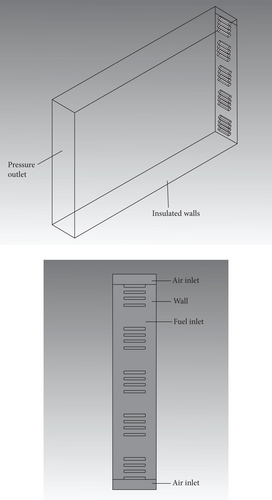
In this paper, a burner of a common domestic water heater is studied numerically [23]. The geometry of the burner used in the present study is the same as that used in the experimental work of a civil combustion water heater in actual use. This has practical significance. Compared with the experimental work, all the details of the burner can be studied regarding the temperature field, velocity field, and pollutant generation under different conditions of burning propane/ammonia-mixed fuels. The general structure of the burner is shown in Figure 1. The burner is a rectangular structure with a length of 100 mm, a width of 20 mm, and a height of 150 mm. At the bottom of the burner, there are 20 evenly distributed burn holes with a length of 10 mm and a width of 2 mm. The propane/ammonia-mixed fuel flows from the fire hole into the burner for combustion. The air inlets are located on both sides of the fire hole. The size of the air inlet is 20 mm long and 4 mm wide. The other side is the flue gas outlet. Such arrangement makes the flame evenly distributed during combustion. The introduction of secondary air on both sides makes the combustion more sufficient. The computational grid is an unstructured grid, and the number of grids is 590000. More details of the geometry can be found in the work of Zhan et al. [23].
2.2. Mathematical Model
The realizable k-ϵ model is selected for the turbulence model considering the simulation accuracy and the working principle of the gas water heater. As tested in other relevant burner studies [24, 25], the realizable k-ϵ model is selected for the turbulence model. Compared with the standard k-ϵ model, the model adds a new transmission equation, which can more accurately solve the free flow transmission problem of mixed flow. This model satisfies the mathematical constraints of the Reynolds stress and provides an analytically derived differential formula for effective viscosity. The combustion mode of the gas water heater modeled in the simulation is partially premixed combustion. The FGM model in the partially premixed combustion model is used to embed the Konnov mechanism of propane/ammonia fuel combustion in CHEMKIN. The DO model is selected to account for the radiative heat transfer of the flue gas. The results under the following four conditions are simulated and calculated: case 1, 0% NH3, 100% C3H8, and ER = 1; case 2, 20% NH3, 80% C3H8, and ER = 1; case 3, 50% NH3, 50% C3H8, and ER = 1; and case 4, 50% NH3, 50% C3H8, and ER = 0.6.
The boundary conditions are set as follows: the velocity inlet boundary condition is adopted at the inlet of the fire hole, the inlet velocity is 2.86 m/s, and the mean mixture fraction is set to 1. The secondary air inlet adopts the velocity inlet boundary condition, the air inlet velocity is 1.11 m/s, and the pressure outlet condition is adopted at the outlet of the burner. The atmospheric environment at the room temperature of 300 K is adopted as the outlet, and the backflow progress variable is set to 1. The turbulence influencing factors at all the boundary conditions are determined by the turbulence intensity and the hydraulic diameter. Table 1 provides a detailed list of the initial conditions such as the gas composition, the flow rate, the air-fuel ratio, and the equivalence ratio for each of the operating conditions.
| C3H8 | NH3 | Equivalence ratio | Temperature (K) | Velocity (m/s) | Air-fuel ratio | Fuel mass flow (g/s) | |
|---|---|---|---|---|---|---|---|
| Case 1 | 100% | 0% | 1 | 300 | 2.86 | 15.67 | 1.04 |
| Case 2 | 80% | 20% | 1 | 300 | 2.86 | 14.92 | 0.92 |
| Case 3 | 50% | 50% | 1 | 300 | 2.86 | 13.38 | 0.74 |
| Case 4 | 50% | 50% | 0.6 | 300 | 2.86 | 13.38 | 0.74 |
2.3. Model Validation
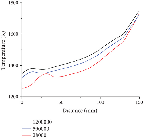
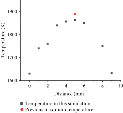
To investigate premixed combustion of ammonia/propane in practical gas burner, it is necessary to use a well-validated detailed chemical-kinetic mechanism model, which can comprehensively describe the combustion phenomenon under a wide range of conditions. The Konnov mechanism [26] used in the present work was developed for the combustion of small hydrocarbon fuels with ammonia. It has been widely used in the ammonia combustion studies. It provides satisfactory performance, especially in the prediction of NOx emission and propagation, compared to most of the available mechanisms [27, 28]. The mechanism contains 129 components and 1231 elementary reactions. Due to the still lacking experience with ammonia and propane fuel mixtures, especially those with high ammonia concentration, such ammonia-added fuel composition can cause numerous control problems for premixed combustion, thus complicating practical burner applications. The computational grid is an unstructured grid, and the number of grids is 590000. In this model, the overall grid size is set to 1 mm, and the grid size is divided into 0.5 mm in the height range of 0-20 mm due to the large temperature gradient near the fire hole, which requires encryption, while the mesh quality is 0.59, and tetrahedral mesh is used as mesh type. On this basis, the grid independence verification is performed in Figure 2. The temperature profiles of the central axis of the combustion chamber under different grid calculations are compared. It is found that the temperature profile of the 280000 grid is unstable at the combustion chamber inlet fire hole, while the overall temperature profiles using 590000 grids and the 1200000 grids are relatively close. Considering the computational cost, the mesh with 590000 grids is chosen for simulation. In order to verify the validity of the model, the simulation results are compared with the paper of A.V. Sepman et al. [27]. The maximum temperatures of propane combustion at different mass fluxes at 10 mm above the burner are measured. When the mass flux is 0.015211 g/cm2 s, the maximum temperature is 1900 K. By utilizing the established model, for the pure propane combustion simulation under the same condition as experiments, the temperature curve at 10 mm above the bottom of the burner is plotted as shown in Figure 3. The maximum temperature is 1869 K, which is less than 2% different from the experimental value, indicating that the numerical model has a certain accuracy. Moreover, from the experimental work of burner of literature, the flame distribution map in the reference [23] shows a triangular cone distribution, stretched from the bottom to the top. A similar trend of temperature can be found from the present simulation results as shown in Figure 4, which proves that the numerical simulation has a certain accuracy.

3. Results and Discussion
3.1. Temperature Field Distribution and Analysis
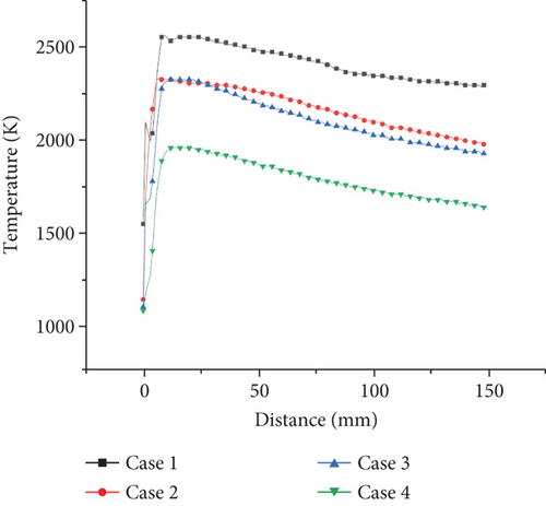
The temperature distribution of the central section of the burner is shown in Figure 4. According to the temperature distribution of the burner interface under the four working conditions, the temperature of the flame center is the highest. The temperature gradually decreases along the center outward. This is due to the fact that in the burner model of this modeling, the bottom of the burner is evenly distributed and the number of fire holes is large. After the gas enters from the fire hole, it burns uniformly in the burner. The secondary air on both sides has a certain velocity. The whole internal structure of the flame has a cone-shaped uniform distribution.
In Figure 4, it can be seen from case 1 that the temperature of the flame center is the highest, about 2500 K, and the temperature gradually decreases outward along the center, and most of the temperature of the burner is about 2300 K. It can be seen from case 2 that the high-temperature zone of the central flame is about 2300 K, and most of the temperature is about 2000 K. The overall temperature of the burner is lower than that of case 1. From case 3, it can be seen that the highest temperature is about 2300 K, which is significantly lower than that when the ammonia ratio is 0 or 0.2. The total flame is mostly around 1900 K, and the combustion area is narrower than the first two, and the combustion area of the flame is more concentrated. In case 3, the total temperature is about 1800 K. The unreacted zone at the low temperature is more significant. Comparing cases 1, 2, and 3, it can be clearly seen that with the increase of ammonia ratio, the highest flame temperature decreases and the reaction zone increases. This is mainly due to the relatively low reactivity of ammonia. NH3 has the larger flame length compared with C3H8, leading to more high-temperature zone in the burner with ammonia added. Reducing the concentration of NH3 in the NH3/C3H8 mixture can significantly increase the combustion temperature of the flame. Compared with cases 3 and 4, it is obvious that with equivalence ratio, decreasing the combustion temperature with an ammonia ratio of 0.5 decreases significantly. The low-temperature areas near the wall are obviously observed. This is due to the increasing amount of extra air that does not participate in the reactions. The heat is absorbed by the excess air and dissipated to the outside.
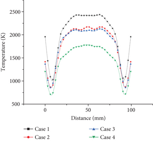
From the temperature distribution on the axis of horizontal vertical direction in Figures 5 and 6, it can be seen that the effect of ammonia mixing ratio on the temperature of the burner is much less than that of the equivalence ratio. When the ammonia mixing ratio is 0, 0.2, and 0.5, the lateral temperature distribution is relatively close, only in the highest temperature zone. Therefore, when the ammonia fuel is applied to the actual burner, increasing the ammonia mixing ratio without changing the equivalence ratio will have little effect on the overall temperature. However, in the oxygen-rich state, it will cause the combustion temperature to decrease significantly and affect the efficiency of the burner.
3.2. Velocity Field Distribution and Analysis
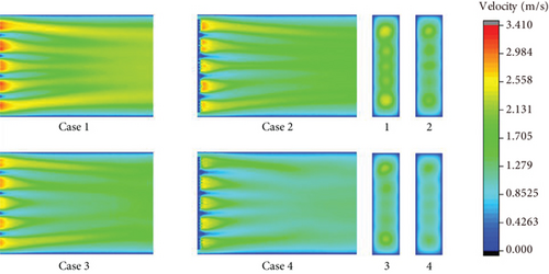
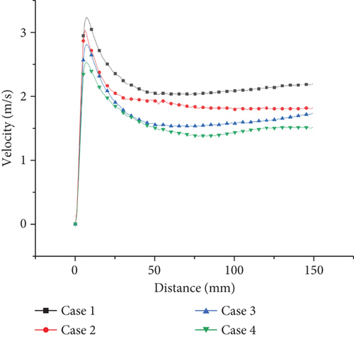
Figures 7, 8–9 show the velocity fields including the high-velocity inlet regions and the internal regions. For propane combustion in case 1, it is shown overall higher velocity compared with cases 2 and 3, in which the average velocity is significantly reduced with ammonia added in the fuel mixtures. Since the inlet velocity is the same in all cases, the velocity trends are the same as in shown in figures. When the ammonia blending ratio is 0.5, the highest velocity inside the burner decreases obviously. Comparing case 2 with case 3, as the equivalence ratio decreases, there is a tendency for both the temperature and the total velocity field to decrease.

3.3. Distribution and Analysis of NO
There are three types of nitrogen oxides in the combustion process according to formation mechanism. They are thermal NO, hydrocarbon fuel fast NO, and fuel-type NO containing N components. The amount of fast-type NO produced during the entire combustion process is negligible compared to the other two, so it is not discussed here.
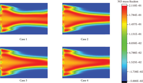
Since the reaction of atomic oxygen and nitrogen molecules requires a large activation energy, a large amount of NO will not be generated before fuel combustion and in the combustion flame. Only in the downstream high-temperature zone of the combustion flame, O2 dissociation can occur, and NO can also be generated. The downstream of the flame accumulates all the enthalpy and makes the temperature here the highest, while the front and middle of the combustion flame are not high-temperature zones. When temperature is higher than 1500 K, the thermal NO generated by combustion will increase exponentially. The formation rate of thermal NO is not only related to temperature but also to the time of air staying in the high-temperature zone. The longer the residence time, the higher the amount of thermal NO generated.
In case 2, when the ammonia blending ratio is 0.2, the highest NO emission increases. This is due to the addition of nitrogen-containing fuel to the fuel and the generation of thermal NO and fuel NO at the same time, which is also a common problem in the combustion of ammonia fuel. When the gas contains nitrogen-containing components, the nitrogen in these compounds can be converted into NH or NH2. NH and NH2 can react with oxygen to form NO through 2NH2 + 2O2 = NO + 2H2O.
However, when the ammonia blending ratio continues to increase, the highest NO content in the high-temperature zone in case 3 decreases. This is due to the increase in ammonia content, which causes the overall temperature of the burner to decrease. In case 4, with the decrease of equivalence ratio, the formation of NO is also significantly reduced. As the equivalence ratio decreases, the amount of air entering the burner increases. Oxygen can significantly inhibit the formation of HNO type NO. Thus, the effective control of NO emissions can be achieved by changing the equivalence ratio. In the case of ammonia fuel, the purpose of reducing NO emissions can be achieved by lean combustion.
Recently, researchers have reached similar conclusions on the NO emission trends of propane-ammonia-blended fuels [28, 29]. Regarding the nonmonotonic trend of NO concentrations, the pathway analysis shows that from the temperature of 900 K to 1000 K, NO formation reactions are less favorable and more NO is consumed. Therefore, the NO concentration first increases and then decreases. Higher formation of active radicals H, O, OH, NH2, NH, and HNO radicals leads to the increase of NO formation with further increase of temperature. This conclusion is similar to the conclusion obtained in this simulation, which also shows that the model has a certain accuracy.
3.4. CO2 Concentration Distribution and Analysis
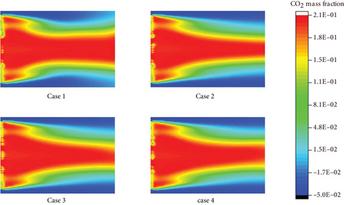
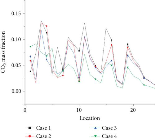
To minimize CO2 emissions from human activities and achieve CO2 emission targets, using ammonia, a carbon-free fuel, is an effective way, so it is necessary to study the CO2 generation concentration in ammonia fuel mixture in Figure 11. It can be seen from cases 1 to 3 that with the increase of ammonia loading ratio, the generation content of CO2 is significantly reduced, which is also the advantage of ammonia in combustion. Compared with cases 3 and 4, as the equivalent ratio decreases, the concentration of CO2 also shows a decrease. This is due to the unreacted air content in the fuel components, so the concentration of CO2 generated in the combustion zone has been significantly reduced.
3.5. Distribution and Analysis of Pollutant Concentration at Burner Outlet
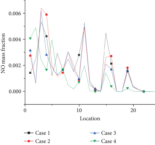
To analyze the concentration of pollutants emitted at the combustor outlet more intuitively, 24 measurement points were selected at the combustor model outlet to read the concentration at each measurement point. The location of the monitoring sites is shown in Table 2.
| X (m) | Y (m) | Z (m) |
|---|---|---|
| 1.46E-02 | 7.96E-03 | 2.10E-01 |
| 1.28E-02 | 1.96E-03 | 2.10E-01 |
| 7.34E-03 | 1.44E-02 | 2.10E-01 |
| 1.57E-02 | 1.64E-02 | 2.10E-01 |
| 3.65E-03 | 7.50E-03 | 2.10E-01 |
| 9.43E-03 | -3.78E-03 | 2.10E-01 |
| 1.63E-02 | -9.42E-03 | 2.10E-01 |
| 5.34E-03 | 2.33E-02 | 2.10E-01 |
| 1.49E-02 | 2.52E-02 | 2.10E-01 |
| 3.45E-03 | -5.77E-03 | 2.10E-01 |
| 1.29E-02 | -1.60E-02 | 2.10E-01 |
| 4.44E-03 | 3.12E-02 | 2.10E-01 |
| 1.12E-02 | 3.37E-02 | 2.10E-01 |
| 1.61E-02 | 3.66E-02 | 2.10E-01 |
| 4.36E-03 | -1.71E-02 | 2.10E-01 |
| 1.54E-02 | -2.33E-02 | 2.10E-01 |
| 4.06E-03 | 4.29E-02 | 2.10E-01 |
| 1.03E-02 | 4.58E-02 | 2.10E-01 |
| 5.00E-03 | -2.55E-02 | 2.10E-01 |
| 1.41E-02 | -3.10E-02 | 2.10E-01 |
| 4.74E-03 | -3.39E-02 | 2.10E-01 |
| 1.56E-02 | -3.91E-02 | 2.10E-01 |
| 4.71E-03 | -4.24E-02 | 2.10E-01 |
| 1.34E-02 | -4.58E-02 | 2.10E-01 |
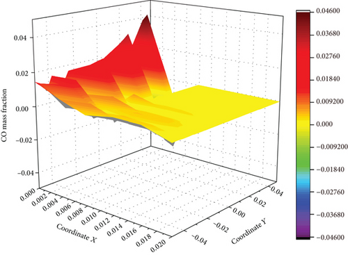
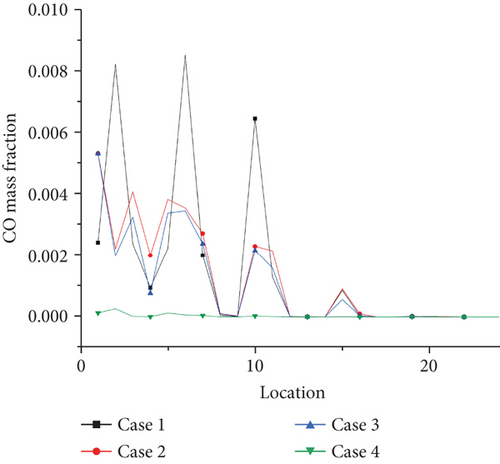
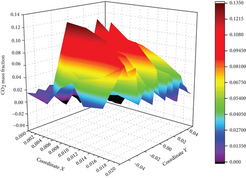
The concentration of CO and CO2 at the outlet is extracted, and the average concentration of CO and CO2 at different coordinates at the outlet of the burner is calculated, according to Figures 12-14–15. It is concluded that compared with the combustion of pure propane, when the ammonia blending ratio is 0.2, the concentration of CO and CO2 is reduced by 17.1% and 12.6%, respectively. When the ammonia blending ratio is 0.5, the concentration of CO and CO2 emissions is reduced more significantly by 31.4% and 25%, respectively.
Emission of NO pollutants is investigated as shown in Figure 16. The NO concentration of each point is extracted at the outlet of the burner by selecting 24 coordinate points as shown in the graph. The average value of NO concentration emission can be calculated at 0, 0.2, and 0.5. At the ammonia ratio, the average concentration of NO generated is 0.04, 0.039, and 0.035. The average concentration of NO obtained at the outlet decreases with the increase of the ammonia ratio, which is due to the increase of the ammonia ratio. The decrease of temperature at the outlet of the burner is more significant, compared with the temperature above 1500 K mentioned in the previous article. The thermal NO produced by combustion will increase exponentially. For every 100 K increase in temperature, the amount of NO production will increase by several times. That is, the increase in the formation of thermal NO at the outlet is greater than that of fuel NO under the increase of ammonia blending ratio. Therefore, in the actual application process, from the perspective of pollutant formation, increasing the ammonia mixing ratio is an effective way to reduce pollutant formation. This is also a great advantage of propane/ammonia fuel for domestic water heaters.
3.6. Carbon Dioxide Baseline Emissions and Analysis
C is the average carbon content of the gas (kg/GJ) and COF is a dimensionless carbon oxidation factor in the process of gas combustion.
In the formula, bi is the number of carbon atoms in the molecular formula of each carbon-containing component of the gas (dimensionless), ai is the volume percentage of each carbon-containing component of natural gas (%), and NCV is the net calorific value of gas (MJ/m3). The calculation method is completed according to the calculation method of natural gas volume calorific value in the national standard GB/T 11062-1998.
In the formula, BE is the baseline emission of the annual project activity replacing the heat supply (t), is the CO2 emission factor (t/(MW·h)), η is the heating efficiency of electric heating equipment when there is no project activity, and HG is the total amount of heat supplied to the annual project activity (J).
According to the case study of a domestic hot water project in a new community of Tianjin in China, every household in the community uses solar water heaters to supply domestic hot water all day, and the daily water consumption in the community is 15000 L/d. In the baseline scenario, the cold water temperature is 283 K, the hot water temperature is 333 K, and the heating heat replaced by the project activity every year is 80%, according to the situation and design requirements of the Tianjin area [30]. The calculated values of carbon emissions of fuels under different components are presented in Table 3.
| CO2 | CO | Sum | NCV | COF | C | EF | BE | |
|---|---|---|---|---|---|---|---|---|
| 22.23% | 0.12% | 0.224 | 0.22 | 24.00 | 0.99 | 2.38 | 17.20 | 9.89 |
| 23.37% | 0.11% | 0.235 | 0.23 | 25.40 | 1.00 | 2.33 | 16.87 | 9.70 |
| 20.29% | 0.09% | 0.204 | 0.20 | 27.50 | 1.00 | 1.69 | 12.21 | 7.02 |
| 19.92% | 0.00% | 0.199 | 0.20 | 27.50 | 1.00 | 1.65 | 11.94 | 6.87 |
By extracting the gas concentration such as carbon dioxide concentration at the outlet of the burner in the simulation calculation results in Table 3, the unit net heating value of different component fuels is calculated. The carbon dioxide emission factor (EF) of propane/ammonia-mixed fuel after combustion in the burner is calculated. When the propane/ammonia-mixed fuel is in the burner, the carbon emission factor (EF) increases with the ammonia blending ratio increasing from 0 to 50%, and the carbon baseline emission (BE) decreases from 9.89 kg/GJ to 6.87 kg/GJ. Meanwhile, the carbon emission under the baseline decreases from 17.20 T to 11.94 T. It is evident that the addition of ammonia component can significantly reduce the carbon emission of the fuel mixture.
The carbon dioxide emission factor (EF) is closer to case 4 when the equivalence ratio is 0.6 and the ammonia ratio is 50% compared with that when the equivalence ratio is 1 and the ammonia ratio is 50%. This is because in this case, the content of carbon monoxide in the exhaust gas of the burner is almost 0, while other parameters are consistent with case 3 working condition, so the overall carbon emission is merely the same. In this simulation, because the overall temperature of the burner is too low and the combustion is not ideal under the working condition of case 4, it is not recommended that the propane/ammonia-mixed fuel is in the lean oxygen combustion condition. At the same time, to meet the conditions of the domestic water heater during the combustion to achieve full combustion and utilization of the fuel, the fuel composition under case 3 is a good choice.
4. Conclusion
- (1)
As the ammonia blend ratio increases, the overall combustion temperature decreases. However, the degree of reduction is small. In the lean oxygen condition, the combustion temperature is significantly reduced and the efficiency of the burner is affected
- (2)
At the outlet of the burner, when the ammonia blending ratio is 0.2, the emission of CO concentration is reduced by 17.1%, and the CO2 concentration is reduced by 12.6%. When the ammonia blending ratio is 0.5, the emission concentration is reduced more obviously, which is 31.4% and 25%, respectively. It shows that the mixed fuel can effectively reduce carbon emissions in domestic water heaters and has great application prospects
- (3)
Ammonia ratio and equivalence ratio do not affect the velocity distribution trend of the overall flow field, while the change of temperature field caused by the increase of ammonia ratio will reduce the velocity distribution in the burner
- (4)
Increasing the ammonia blending ratio is an effective way to reduce carbon emissions. Even in the presence of nitrogen-containing fuels, the emission of NO pollutants remains basically unchanged due to the decrease of combustion temperature
- (5)
The calculation of carbon dioxide emissions under different operation conditions shows that when the ammonia blending ratio is 0.5, carbon dioxide emissions can be significantly reduced. The baseline carbon dioxide emissions can be reduced from 17.20 T to 11.94 T. Under this condition, the propane/ammonia fuel is suitable for reducing emissions of water heaters
Conflicts of Interest
The authors declare that they have no known competing financial interests or personal relationships that could have appeared to influence the work reported in this paper.
Acknowledgments
This work was supported by the Science and Technology Project of Guangdong Provincial Department of Transportation (No. Science and Technology 2017-02-021) and 2023 Basic and Applied Basic Research Project of Guangzhou Municipal Bureau of Science and Technology (No. SL2022A04J00794).
Open Research
Data Availability
Data will be made available on request.


