Vanadium Redox Flow Battery Using an N-Doped Porous Carbon-Coated Positive Electrode Derived from Zeolitic Imidazolate Framework-8-Coated Graphite Felt
Abstract
The poor electrochemical activity and low wettability of graphite felt (GF) electrodes significantly limit the energy efficiency and power of vanadium redox flow batteries (VRFBs). To solve these problems, we developed an N-doped porous carbon-coated electrode by the carbonization of zeolitic imidazolate framework-8- (ZIF-8-) coated GF. By controlling the carbonization temperature, the effects of temperature on the structural morphology, pore structure, and amount and type of functional groups of the electrode were confirmed. In addition, the effect of the change in the pore structure and the amount and type of functional groups on the electrocatalytic activity for the vanadium redox reaction was demonstrated. The synthesized N-doped porous carbon-coated electrode, which showed the best electrochemical activity, had a sufficient amount of nitrogen functional groups with a high ratio of graphitic N and the highest surface area and pore volume among all the samples, providing abundant active sites for the VO2+/VO2+ redox reaction. The VRFB fabricated using prepared electrode exhibited energy and voltage efficiencies of 70.44% and 73.44%, respectively, at 200 mA cm-2, which were 11.77% and 11.08% higher than those of the bare GF electrode. Furthermore, the modified battery operated effectively at a high current density of 350 mA cm-2. The energy efficiency exhibited excellent stability over 500 charge/discharge cycles at 250 mA cm-2. Hence, this study presents a promising method for the development of high-performance VRFB electrodes.
1. Introduction
The depletion of existing energy resources and environmental problems caused by the excessive utilization of fossil fuels have increased the interest in renewable energy applications. However, renewable energy resources, such as wind and solar power, cannot respond stably to energy demands owing to their intermittency and volatility. Therefore, it is essential to develop large-scale energy storage systems (ESSs) for integrating renewable energy. Among the various ESSs, vanadium redox flow batteries (VRFB) have attracted considerable attention for large-scale energy storage applications owing to their advantages, such as long lifespan, flexible design, and safety [1–4].
In VRFBs, the electrode surface and morphological properties significantly impact the battery performance because the redox reactions occur at the interface between the electrode and the electrolyte [5, 6]. Currently, the most extensively used electrode material is graphite felt (GF), which has superior chemical stability, high electrical conductivity, excellent mechanical properties, and strong corrosion resistance in acidic electrolytes. However, GF limits the electrochemical performance of VRFB because of its poor catalytic activity due to its hydrophobic properties, small specific surface area, and insufficient active sites [2–4]. To improve the catalytic activity of GF, various surface treatment methods, such as the grafting of oxygen-containing groups, heteroatom doping, and introduction of catalysts, such as metals or carbon-based materials, onto the electrode surface, have been proposed. Grafting with oxygen-containing groups or doping with heteroatoms can increase the number of active sites and surface wettability of GF [4, 7]. Noble metals (Pt, Ir, etc.) [8, 9] and metal oxides (TiO2, ZrO2, etc.) [10, 11], which are effective catalysts owing to their excellent electrical conductivity, promote the redox reaction of vanadium ions; however, they can be easily detached, eventually leading to electrolyte contamination. Carbon-based catalysts, such as mesoporous carbon, pristine carbon nanotubes, and graphene, which have abundant pore structures and large surface areas, can increase the adsorption and transport of active species, but their insufficient active sites limit their catalytic performance [12–14]. Therefore, developing catalysts with hydrophilicity, high specific surface area, and abundant active sites is key to improving the VRFB performance. Recently, metal-organic frameworks (MOFs) have been considered ideal precursors for porous carbon materials containing functional groups owing to their high surface area, tunable porosity, and functional groups [15–20]. To date, several studies on GF electrode modification to improve VRFB performance using these MOF subtypes, UIO-66, zeolitic imidazolate framework-8 (ZIF-8), and ZIF-67 have been reported [11, 21–23]. In particular, ZIF, containing an aromatic methylimidazole ligand can be easily synthesized and is highly enriched with nitrogen, unlike other MOFs based on amino ligands [24, 25]. However, to the best of our knowledge, the effects of temperature-dependent changes in the morphology, pore structure, and functional groups of ZIF coating on its electrochemical activity have not been confirmed thus far.
In this study, we fabricate an N-doped porous carbon-coated electrode by carbonizing ZIF-8-coated GF. The electrodes synthesized by carbonization at different temperatures are compared to confirm the effect of temperature on the structural morphology, pore structure, and functional group amount and type. In addition, the effect of the electrocatalytic activity on the vanadium redox reaction in terms of the change in the pore structure and the amount and type of functional groups is demonstrated. The synthesized electrode, which included a high ratio of graphitic N and had the highest surface area and pore volume, provided abundant active sites; therefore, it exhibited the best electrochemical properties among all the samples. In a single-cell test, the voltage efficiency (VE) and energy efficiency (EE) of the VRFB fabricated with the N-doped porous carbon-coated electrode were increased by 9.29% and 9.61%, respectively, compared with those of the bare GF electrode at a current density of 150 mA cm-2. Furthermore, the VRFB containing the prepared electrode demonstrated the stability of the redox reactions, even at a high current density of 350 mA cm-2. These results suggest that the N-doped porous carbon-coated electrode is a promising candidate for improving the electrochemical performance of VRFBs.
2. Materials and Methods
2.1. Synthesis of ZIF-8-Coated Graphite Felt (ZGF)
Zinc nitrate hexahydrate (Zn(NO3)2 6H2O, 98.0%) and 2-methylimidazole (Hmim, 99%) were purchased from Sigma-Aldrich. Extrapure grade methyl alcohol (99.5%) and hydrochloric acid (35%) were purchased from Samchun Chemical Co., Ltd., and Daejung Chemicals & Metals, respectively. Before use, GF (JNTG Co., Ltd., Republic of Korea) was soaked in acetone, washed by ultrasonication for 30 min to remove impurities, and then dried at 60°C overnight. Solution A was prepared by dissolving 1.21 g of zinc nitrate hexahydrate in 65 mL of methanol. Solution B was prepared by dissolving 1.32 g of 2-methylimidazole in 15 mL of methanol. The molar ratio of zinc nitrate hexahydrate to 2-methylimidazole was 1 : 4. The washed GF was impregnated with solution A for 30 min. Subsequently, solution B was added, and ultrasonication was performed for 3 h. Next, the obtained GF was washed several times using clean methanol and dried at 60°C overnight to obtain the ZGF sample.
2.2. Synthesis of N-Doped Porous Carbon-Coated GF (NPGF)
NPGF samples were synthesized by the carbonization of the ZGF sample. ZGF was carbonized at 700, 800, or 900°C for 3 h in an N2 gas atmosphere using a tubular furnace and then cooled to 25 ± 5°C. The temperature was increased at a rate of 5°C min-1, and the gas flow rate was maintained at 300 sccm. After carbonization, the samples were stirred in 100 mL of 3 M HCl for 12 h. The samples were washed several times with deionized water until the pH became neutral and then vacuum dried at 60°C overnight. The obtained samples were denoted as NPGF–700, NPGF–800, and NPGF–900, respectively, according to the carbonization temperature.
2.3. Characterization
The crystalline phases were analyzed using X-ray diffraction (XRD; MiniFlex, Rigaku). The morphology of the electrode surface was analyzed by field emission scanning electron microscopy (FE-SEM; SU8000, Hitachi) at an acceleration voltage of 5 kV. The surface area and pore size distribution were determined using a gas sorptometer (Micromeritics ASAP2460M) by the Brunauer-Emmett-Teller (BET) method. The elemental species and valence bond states on the surfaces of the bare GF and NPGF samples were investigated by X-ray photoelectron spectroscopy (XPS; K-Alpha, Thermo Scientific). The degrees of graphitization of the samples were investigated using a micro-Raman spectrometer (Raman; DXR-3xi, Thermo Fisher Scientific). The hydrophilicities of the bare GF and NPGF samples were investigated using a contact angle analyzer (Phoenix 300, SEO).
The electrochemical properties of the electrodes were analyzed using cyclic voltammetry (CV) and electrochemical impedance spectroscopy (EIS) (potentiostat/galvanostat/EIS system; SP-240, Bio-Logic Science Instruments). CV and EIS analyses were conducted in a three-electrode cell comprising a working electrode (sample with a diameter of 5 mm), counter electrode (bare GF with a size of 1 × 3 cm2), and reference electrode (Ag/AgCl) in a positive electrolyte (0.05 M V(IV)/1.0 M H2SO4). The CV measurements were performed at different scan rates of 5, 10, 20, and 30 mV s-1 in the potential range of 0.0–1.5 V (vs. Ag/AgCl). EIS measurements were conducted using the same device in the frequency range of 10-1 to 105 Hz by applying an amplitude of 10 mV.
2.4. Single-Cell Performance of VRFB
To evaluate the VRFB single-cell performance, an in-house-designed VRFB comprising copper current collectors, graphite bipolar plates, electrodes (33 mm × 33 mm × 4.2 mm), polytetrafluoroethylene flow frames, and a Nafion 115 membrane (60 mm × 60 mm) was used. The prepared samples were used as a positive electrode, respectively, and bare GF was used as the negative electrode. The positive (50 mL of 1.6 M V(IV)/2.0 M H2SO4) and negative (50 mL of 1.6 M V(III)/2.0 M H2SO4) electrolytes were added to the VRFB single cell and circulated at a rate of 50 mL min-1 using a peristaltic pump. The galvanostatic charge and discharge tests were conducted at various current densities ranging from 50 to 350 mA cm-2 in the voltage range of 0.8–1.7 V. The cycling test of VRFB with an N-doped porous carbon-coated electrode was performed at a constant current density of 250 mA cm-2. All the cell tests were conducted using a WBCS3000S3 battery test system (WonATech Co., Ltd.).
3. Results and Discussion
Figure 1 shows the XRD and SEM results of the bare GF and NPGF samples. The structural characteristics of the samples were confirmed using XRD (Figure 1(a)). Bare GF exhibited peaks at 2θ = 26° and 43° corresponding to graphitic carbon [26]. In contrast to bare GF, the ZGF samples exhibited peaks at 7.5°, 10.5°, 12.8°, and 18.2°. These peaks correspond to ZIF-8, indicating the presence of crystallized ZIF-8 on the GF surface [27]. The NPGF samples showed patterns identical to those of bare GF, and no other diffraction peaks were observed, except for the carbon peaks. This implies that no impurities other than graphitic carbon are present. The surface morphology of each sample was confirmed using SEM (Figures 1(b)–1(k)). Bare GF (Figures 1(b) and 1(c)) has a smooth and clean surface. In contrast, ZGF (Figures 1(d) and 1(e)) has a uniform coating of crystallized particles on the surface, and these particles were identified as ZIF-8 by XRD. Surface morphologies different from those of the ZGF samples were observed for the NPGF samples. The coating layer on the NPGF–700 surface (Figures 1(f) and 1(i)) was connected in the form of a spider web. This spider-web shape is attributed to the carbon networks formed by the transformation of ZIF-8 into ZnO and carbon at approximately 700°C (Supporting Information, Figure S1) [17, 28]. The NPGF–800 surface (Figures 1(g) and 1(j)) exhibited a more connected and denser coating than that of NPGF–700. This is because the decomposed ZIF-8 particles undergo shrinkage, deformation, and densification as the carbonization temperature increases [29, 30]. Compared to NPGF–700 and NPGF–800, NPGF–900 (Figures 1(h) and 1(k)) exhibited a completely densified coating layer.
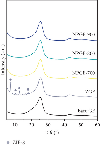
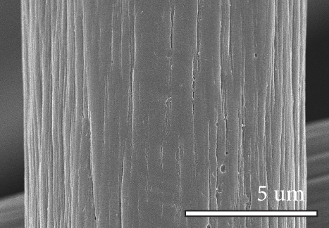
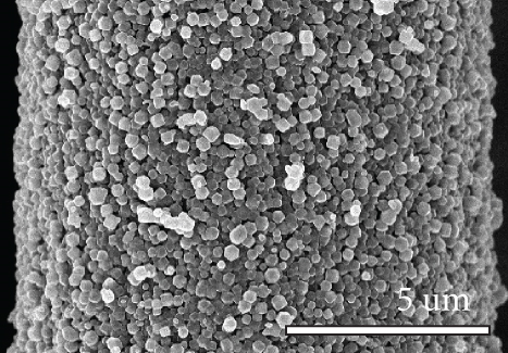
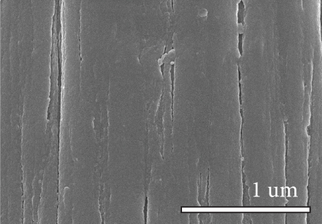
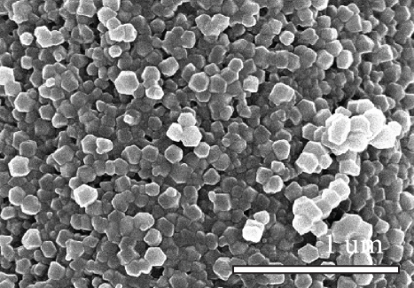
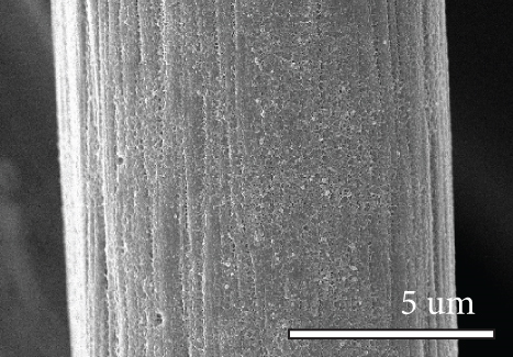
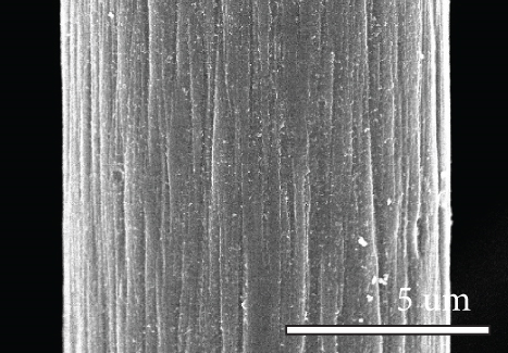

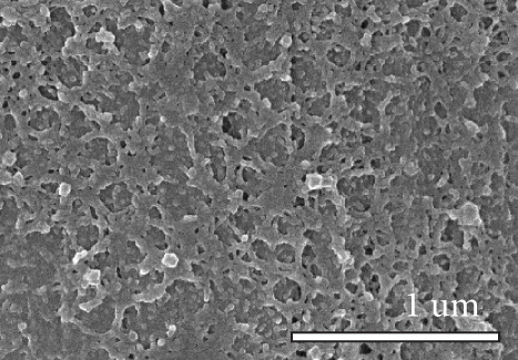
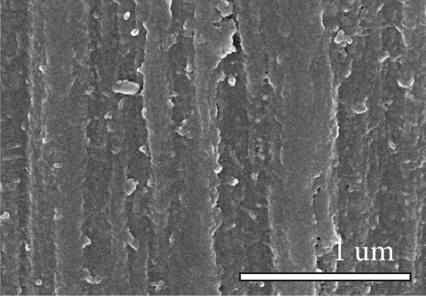
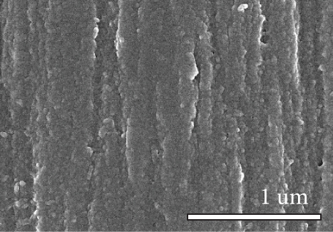
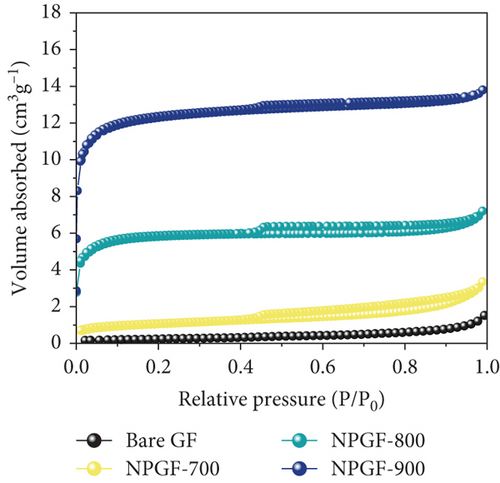
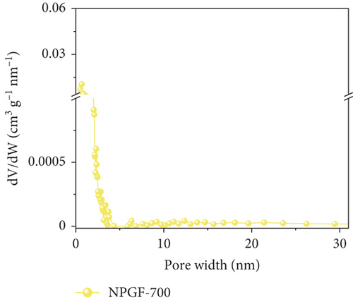
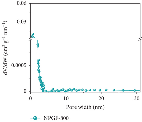
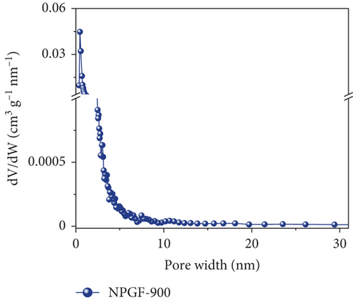
Figure 2 shows the N2 adsorption–desorption isotherms of the bare GF and NPGF samples. The specific surface area and pore volume were analyzed using the BET method. As shown in Figure 2(a), the NPGF samples have different hysteresis loops than that of bare GF, indicating that they have a porous structure [2]. Bare GF had almost no pores, whereas pores were observed in the NPGF samples (Figure 2(b)). All the NPGF samples possessed mesopores (2–50 nm). Moreover, the volume of mesopores for NPGF–700, NPGF–800, and NPGF–900 are 2.64, 3.52, and 3.87 (10-3 cm3 g-1), respectively, indicating an increase in total pore volume as the carbonization temperature increased (Figures 2(c)–2(e)). This is because mesopores are formed by carbon networking during carbonization, and the carbon network became more connected and densified as the temperature increased [17, 28, 29]. The NPGF–900 sample not only showed higher volumes of mesopores than NPGF–700 and NPGF–800 but also had a significantly high volume of micropores (<2 nm) (Figure 2(e)). The micropores are formed by Zn that reduced from ZnO, evaporation at approximately 900°C (Supporting Information, Figure S1) [28]. The surface area of the samples increased in the order of bare GF < NPGF–700 < NPGF–800 < NPGF–900 with values of 0.80, 3.39, 20.06, and 42.42 m2 g-1, respectively. Although the surface roughness of NPGF–700 was higher than that of NPGF–800 and NPGF–900 as shown in SEM (Figures 1(i)–1(k)), the specific surface area increased with the increasing carbonization temperature. The specific surface area can also be affected by the roughness of morphology; however, pore structure and volume are the primary factors influencing the specific surface area. Therefore, the increase in the specific surface area was consistent with the increase in the mesopore volume at high carbonization temperatures, as confirmed in the BET. The NPGF–900 sample had the highest surface area among all the samples because it had the highest mesopore volume, as well as a high micropore volume. This increased surface area was expected to provide abundant catalytically active sites for its application as an electrode in VRFB systems.

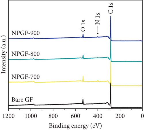
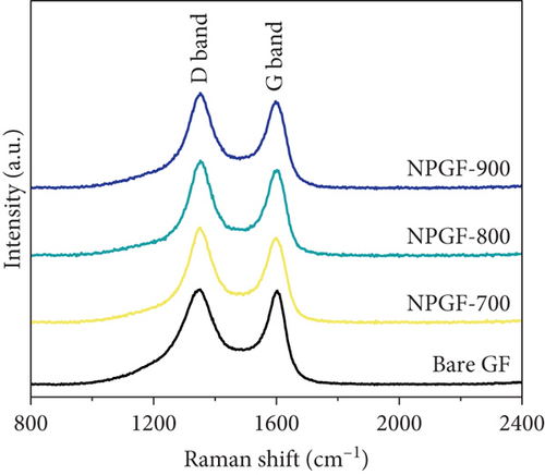
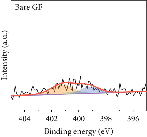
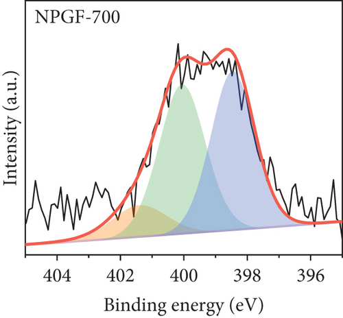
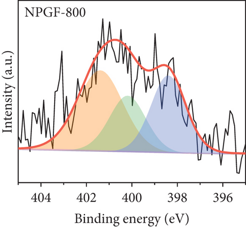
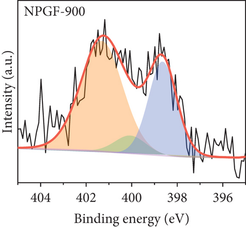
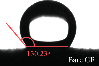
The elemental composition of the electrode surface was analyzed by XPS (Figure 3). The C, N, and O contents of each sample are summarized in Table 1. As shown in Figure 3(a), the survey scan spectrum of bare GF shows only peaks for carbon (at approximately 284.5 eV) and oxygen (at approximately 531 eV), but no nitrogen peak (approximately 401 eV) [31, 32]. In contrast, the survey scan spectra of the NPGF samples show an additional nitrogen peak. In particular, the nitrogen content of bare GF, NPGF–700, NPGF–800, and NPGF–900 is 0.28, 4.55, 2.47, and 2.25 at%, respectively (Table 1). These results indicate that nitrogen was introduced into the ZIF-8-derived carbon coating on the GF surface and that the carbonization temperature affected the amount of nitrogen. As the carbonization temperature increased, the amount of nitrogen functional groups decreased owing to the removal of nitrogen and the cracking of unstable C–N bonds [32–34]. To further investigate the effect of the carbonization temperature on the nitrogen functional groups, high-resolution N 1s spectra were obtained for all the samples (Figures 3(d)–3(g)). The N 1s spectra were deconvoluted into three peaks assigned to graphitic N (401.3 eV), pyrrolic N (400.1 eV), and pyridinic N (398.3 eV) [17, 32, 35]. Pyridinic N corresponds to one nitrogen atom bound to two C atoms in a hexagonal ring, pyrrolic N corresponds to a nitrogen atom bound to a five-membered heterocyclic ring, and graphitic N refers to a nitrogen atom located in a graphitic carbon framework [36]. As shown in Figures 3(d)–3(g), the high-resolution N 1s spectra of the NPGF samples show distinct peaks, whereas that of bare GF has an unclear nitrogen peak. Compared with the N 1s spectra of the NPGF samples, the intensities of the pyridinic N, pyrrolic N, and graphitic N peaks remained almost constant, decreased, and increased with the increasing carbonization temperature, respectively (Figures 3(e)–3(g)). This is because pyrrolic N is thermally unstable, whereas graphitic N and pyridinic N are stable at relatively high temperatures. In addition, the pyrrolic N, which is supplied with sufficient energy at high temperatures, continuously converts to graphitic N [34, 37, 38]. As previously reported, graphitic N is known to contribute to the main active sites for redox reactions as it is more stable in acidic environments than the other two forms of nitrogen [35, 36, 39]. Thus, graphitic N is likely to effectively improve the electrocatalytic activity for the VO2+/VO2+ redox reaction. The surface microstructures of the bare GF and NPGF samples were analyzed by Raman spectroscopy (Figure 3(b)). The samples exhibited two distinct diffraction peaks at 1350 cm-1 (D band) and 1587 cm-1 (G band), representing sp3-disordered and sp2-ordered graphitic carbon, respectively. The intensity ratio of the D to G bands (ID/IG) reflects the degree of carbon defects [40, 41]. The ID/IG values of NPGF–700 (1.16), NPGF–800 (1.11), and NPGF–900 (1.09) are higher than that of bare GF (1.01), because nitrogen functional groups were introduced into the NPGF samples, as confirmed by XPS. Because the electrodes of the VRFB are in direct contact with the electrolyte and the electrochemical reaction occurs on the electrode surface, electrode wettability is a key factor influencing the performance of VRFBs [42, 43]. The wettability of the electrode was confirmed by measuring the contact angles of the bare GF and NPGF samples (Figures 3(h)–3(k)). The hydrophobic nature of bare GF is shown in Figure 3(h), with a wetting angle of 130.2°. In contrast, the wetting angle of the NPGF samples could not be measured due to the immediate absorption of water droplets, indicating that these samples are highly hydrophilic (Figures 3(i)–3(k)). Additionally, an electrolyte immersion test was performed. As shown in Figure 3(c), bare GF did not sink when immersed in the electrolyte, whereas all the NPGF samples exhibited enhanced hydrophilicity and sank. These results further confirm that the untreated bare GF has hydrophobic properties, whereas the NPGF samples have a hydrophilic surface after surface modification. The improved wettability of the NPGF samples is attributed to nitrogen doping [44].



| Sample | C 1s (atom %) | O 1s (atom %) | N 1s (atom %) |
|---|---|---|---|
| Bare GF | 89.82 | 9.82 | 0.28 |
| NPGF–700 | 85.39 | 9.84 | 4.55 |
| NPGF–800 | 88.71 | 8.7 | 2.47 |
| NPGF–900 | 89.43 | 8.2 | 2.25 |
The catalytic effect of all the electrodes on the VO2+/VO2+ redox reaction was confirmed by conducting CV and EIS tests. Figure 4(a) shows the CV results for the VO2+/VO2+ redox couple. The peak current density ratio (–Ipa/Ipc) and peak potential separation (ΔEp), which are key evaluation criteria for the electrochemical activity of an electrode, were compared [45]. The –Ipa/Ipc values of the bare GF, NPGF–700, NPGF–800, and NPGF–900 samples are 1.59, 1.19, 1.03, and 1.05, respectively, confirming that the –Ipa/Ipc values of the NPGF samples were significantly closer to 1 than that of bare GF. These results indicate that the redox reaction occurs more reversibly in the NPGF sample than in bare GF. Furthermore, compared with the ΔEp of bare GF (475 mV), those of NPGF–700 (442 mV), NPGF–800 (319 mV), and NPGF–900 (273 mV) decreased with increasing carbonization temperature. These improvements in the ΔEp values indicate the enhancement of the electrochemical kinetics of the VO2+/VO2+ redox reaction [46]. To confirm the effect of the cleaning step using HCl to remove the remained metal oxide in the synthesis process on the electrochemical activity of NPGF samples, the sample that underwent only the washing step (HCl-cleaned GF) was examined by using the CV test. The HCl-cleaned GF showed improved reversibility than the bare GF due to the effect of acidic treatment (Supporting Information, Figure S2). Although the cleaning step contributes to improve the electrochemical activity, it is not a main reason for enhanced electrochemical activity of NPGF samples. The enhanced electrochemical activity of the NPGF samples is directly related to the specific surface area and presence of nitrogen functional groups that catalyzes the VO2+/VO2+ redox reaction. In particular, although NPGF–700 has the highest nitrogen content, NPGF–900 had the best electrochemical activity because it not only has adequate nitrogen functional groups with a high ratio of graphitic N but also has the highest specific surface area, as confirmed by XPS and BET. To compare the mass-transfer performance of the electrodes, the relationship between the peak current density (Ipa or Ipc) and the square root of the scan rate (v1/2) was plotted according to the CV curves obtained at different scan rates (Figure 4(b)). Ipa or Ipc and v1/2 have a linear relationship, indicating that the redox reaction on all the electrodes is dominated by the mass-transfer process [47]. Generally, a steep slope of these curves implies a fast mass-transfer process [48, 49]. The slopes of the NPGF samples are steeper than that of bare GF because the wettability of the electrode increased owing to nitrogen doping. In particular, the active material migrated the fastest on the surface of the NPGF–900 electrode, despite the presence of a small amount of nitrogen functional groups. These results indicate that the mass-transfer kinetics of NPGF–900 were the most improved among all the sample because of the nitrogen functionalization and high porosity of the electrode. Figure 4(c) shows the Nyquist plots obtained from EIS analysis, which were used to confirm the charge-transfer properties of each sample surface. All the Nyquist plots are composed of semicircles and diagonal lines, indicating that the VO2+/VO2+ redox reaction is controlled by charge-transfer and diffusion processes on the electrode [35, 50]. In the high-frequency region, the first intersection point of the curve with the real axis of the plot represents the bulk solution resistance (Rs) of the electrolyte and electrode, and the radius of the semicircle in the high- to mid-frequency range represents the charge-transfer resistance (Rct) [51]. As shown in Figure 4(c), the order of the Rct values of the electrodes are bare GF > NPGF–700 > NPGF–800 > NPGF–900, indicating reduced polarization due to more favorable adsorption of active species on the nitrogen-containing NPGF sample electrodes [52]. Notably, NPGF–900 had a significantly lower Rct value than all the other samples because of its functional groups and high pore volume, which facilitated electrolyte transport. This is consistent with the CV results, demonstrating that the N-doped, highly porous, carbon-coated structure significantly mitigates kinetic polarization.
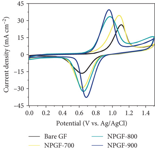
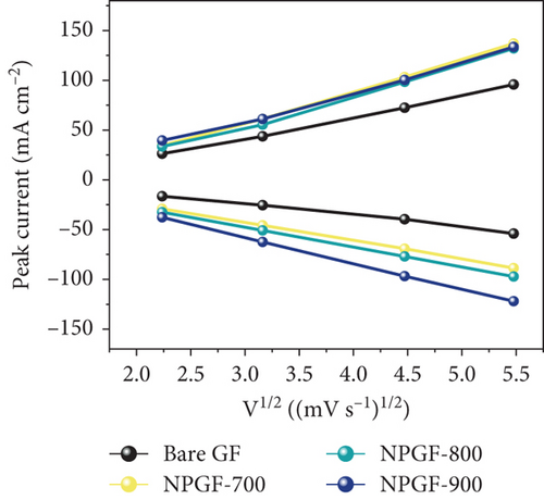
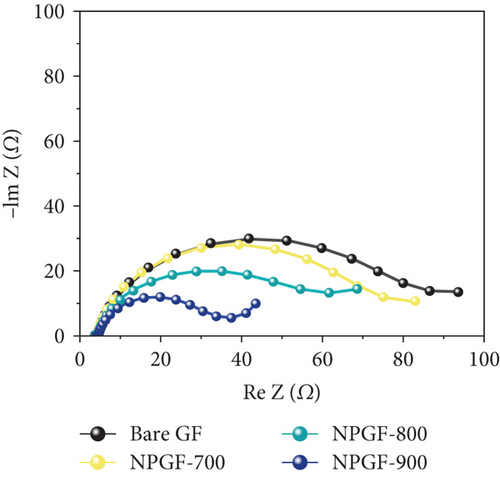
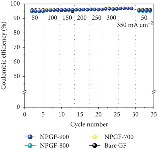
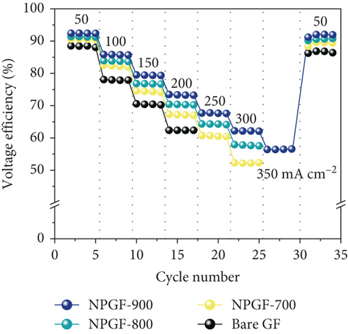
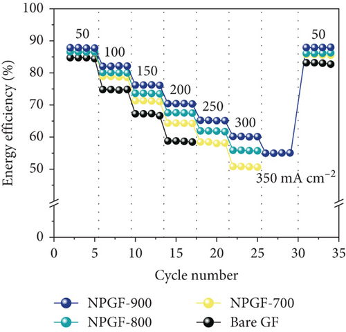
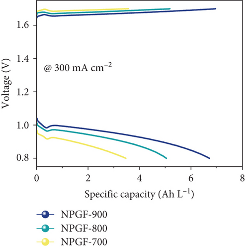
Figure 5 shows the results of a charge-discharge test using a single cell to evaluate the effect of the N-doped porous carbon-coated electrode on the VRFB performance. As shown in Figure 5(a), the coulombic efficiency (CE) of the VRFB single cells was not significantly different because the same electrolyte and membrane were applied to all the flow battery systems [53, 54]. However, the VE of the VRFB single cells differed depending on the electrode used (Figure 5(b)). At all current densities, the VE of the VRFB fabricated with NPGF-900 was the highest among all the samples. In particular, the VE values of the VRFB fabricated using bare GF, NPGF–700, and NPGF–800 are 62.36%, 67.17%, and 70.36%, respectively, whereas that of the VRFB fabricated using NPGF–900 was the highest with a value of 73.44% at 200 mA cm-2. Generally, a higher VE implies a smaller degree of battery polarization [55, 56]. NPGF–900 has a highly porous structure and abundant graphitic N for the vanadium redox reaction, thereby promoting vanadium ion adsorption and accelerating charge transfer and mass transport to reduce battery polarization. The EE calculated using the CE and VE values (EE = VE × CE) is a key indicator for evaluating battery performance [53]. Similar to the trend observed for the VE, the EE of the VRFB fabricated with NPGF–900 was highest among all the VRFBs at all current densities (Figure 5(c)). At 200 mA cm-2, the EE of the VRFB containing NPGF–900 is 70.44%, which is 11.77%, 6.2%, and 2.91% higher than those of bare GF, NPGF–700, and NPGF–800, respectively. The difference in the EE values between the samples increased with increasing current density, indicating the excellent rate performance of the NPGF–900 electrode [57]. In addition, VRFB containing the NPGF–900 electrode operated continuously with an EE of 55.06% at a high current density (350 mA cm-2), whereas the other samples failed. These results demonstrate that the introduction of an N-doped porous carbon-coated electrode is effective for reducing polarization, which contributes to the effective operation of the VRFB, even at high current densities. The specific capacity at a current density of 200 mA cm-2 for NPGF–700 (13.95 Ah L-1), NPGF–800 (13.35 Ah L-1), and NPGF–900 (14.45 Ah L-1) is higher than that of bare GF (12.58 Ah L-1) (Figure 5(d)). In addition, at high current densities of 300 mA cm-2, the batteries fabricated using the NPGF–700, NPGF–800, and NPGF–900 electrodes maintained effective capacities of 3.56, 5.18, and 6.95 Ah L-1, respectively, whereas the operation of the VRFB based on bare GF was limited (Figure 5(e)). The VRFB fabricated with NPGF–900, which exhibited the best electrochemical performance, was compared with surface-treated electrodes prepared using various previously reported methods (Figure 5(f)) [4, 58–65]. The N-doped porous carbon-coated electrode derived from the ZIF-8 coating is sufficiently competitive to improve the performance of VRFBs.


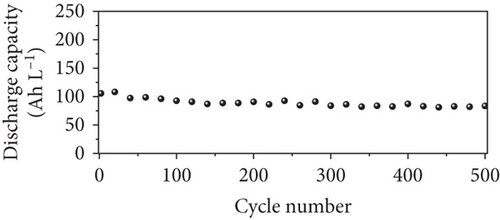
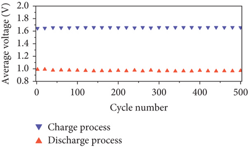
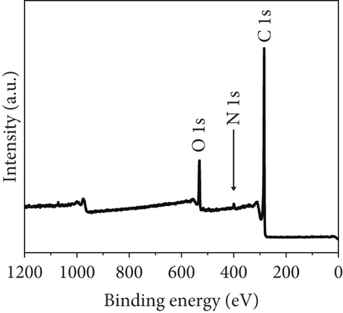
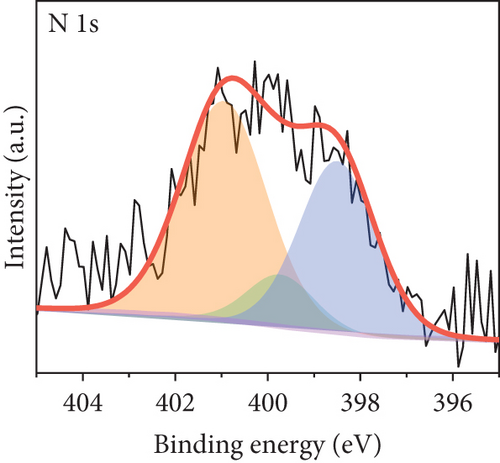
The long-term cycling stability of the VRFB containing the NPGF–900 electrode was tested for 500 cycles at a constant current density of 250 mA cm-2. As shown in Figure 6(a), the EE, CE, and VE values remained almost constant for 500 cycles, indicating the high cycle stability of the NPGF–900. Figure 6(b) shows the discharge capacity of the VRFB over 500 cycles. The first and last discharge capacities are 105.63 and 83.52 Ah L-1, respectively, and the decrease in the discharge capacity is attributed to the imbalances in the volume and concentration of the vanadium electrolyte between the positive and the negative electrodes, which was due to the inevitable vanadium ion crossover during VRFB operation [66, 67]. As shown in Figure 6(c), the average charge and discharge voltages remained almost constant throughout the test, demonstrating the excellent electrode stability. In addition, the nitrogen functional groups were retained after the cycling tests. As shown in Figure 7(a), the survey scan spectrum exhibited a nitrogen peak and a nitrogen content of 2.63 at% was maintained. In addition, the presence of graphitic N, which catalyzes the VO2+/VO2+ redox reaction, was confirmed in the high-resolution N 1s spectrum, even after the cycling test (Figure 7(b)). These results demonstrate that NPGF–900 exhibits excellent catalytic performance and cycling stability.

4. Conclusions
In this study, an N-doped porous carbon-coated electrode was developed via a carbonization process based on a ZIF-8 coating to enhance the electrochemical performance of VRFBs. We confirmed the changes in the pore structure and the amount and type of nitrogen functional groups with temperature by regulating the carbonization temperature and demonstrated the effects of these altered structures and functional groups on the electrochemical activity. BET analysis confirmed that the higher the carbonization temperature, the more connected and densified the carbon network; consequently, the volume of mesopores increased. In particular, at 900°C, in addition to the formation of mesopores, micropores were formed due to Zn evaporation. Moreover, it was confirmed that the amount of nitrogen functional groups decreased because the cracking of unstable C–N bonds increased as the carbonization temperature increased; however, the ratio of graphitic N, which improves the electrocatalytic activity of redox reactions, increased. The CV and EIS results demonstrated that NPGF–900, with a high specific surface area, pore volume, and graphitic N content, has the highest electrochemical activity, with reduced mass-transfer and charge-transfer resistances among all the samples. Furthermore, in a single-cell test, the VRFB fabricated using NPGF–900 exhibited excellent battery performance, with the highest EE, high operating current densities, and increased discharge capacities. The VRFB fabricated with NPGF–900 as the positive electrode could operate for 500 cycles without an EE reduction at 250 mA cm-2, and the nitrogen functional groups were maintained in the VRFB after the cycling test. Therefore, this study provides novel strategies for the development of high-performance electrodes for application in VRFBs by solving the problems of poor stability on the electrode surface and insufficient active sites for carbon-based catalysts.
Conflicts of Interest
The authors declare that there are no conflicts of interest regarding the publication of this paper.
Acknowledgments
This work was financially supported by the Materials/Parts Technology Development Program (20017190) funded by the Ministry of Trade, Industry & Energy (MOTIE) of Korea and the Research Program from Korea Institute of Industrial Technology (EM230001). Open Access funding is enabled and organized by NST 2023.
Open Research
Data Availability
The data that support the findings of this study are available from the corresponding authors upon reasonable request.


