Numerical Investigation on Charging–Discharging of a PCM Using PV and Thermal Oil for Injera Baking Application
Abstract
In Ethiopia, where millions rely on biomass, charcoal, and animal dung for energy, the predominant use is in baking injera, constituting over 50% of energy consumption. This traditional practice adversely affects the health of women and children and hampers education. To address this, solar energy is explored as a sustainable alternative. However, the intermittent nature of solar power poses challenges. A solution involves integrating a thermal storage system, ensuring a consistent and reliable energy supply for the crucial task of baking injera, ultimately improving lives and empowering communities. This study investigates the thermal characteristics of the charging and discharge processes and main heat transfer processes in the injera baking system with PV which was integrated with the thermal storage system. Our study journey began with exploring relevant papers and system designs, collecting and analyzing data, and, in addition, performing mathematical and numerical models. A numerical simulation was conducted using a finite-difference computational model for the thermal storage containing PCM and thermal oil. The thermal oil was used to store energy and transfer heat; furthermore, the developed computational models were analyzed using MATLAB programming software. The numerical simulation result by using solar radiation data from Addis Ababa showed that the thermal storage has the capacity to store about 33.03 MJ during charging using constant heat flux which was from the PV. The amount of energy discharged from the PCM was 13.1 MJ, and from the thermia oil, it was 3.50 MJ using natural convection heat transfer, and the discharging and overall efficiency of the system were about 50.2% and 46.67%, respectively. Also, the baking pan surface temperature stayed between 220°C and 146.4°C for about 3 h. This result was compared with different papers, and it can be concluded that the numerically investigated solar-powered injera baking integrated with thermal storage showed a promising result.
1. Introduction
Energy is necessary for all societal development and economic prosperity. About 79% of the people in Ethiopia live in rural areas [1] and use conventional biomass energy sources for heating and cooking in huge amounts. Due to the country’s restricted access to modern electricity, the energy sector in Ethiopia faces some issues [2]. Technical, human capacity, financial, economic, underdeveloped rural energy markets and infrastructures, information, and political hurdles are the main obstacles to the harvesting and growth of renewable energy [3]. Access to modern energy sources is crucial for economic growth, improving livelihoods, and advancing the country’s development agenda by enhancing education, lowering indoor air pollution, and promoting environmental sustainability [4].
The national dish of Ethiopia, injera, is a flatbread with a distinctive flavor. It is a circular pancake with a sour and pleasant texture, a thickness of 2–4 mm, and a diameter of about 58 cm, and to be properly prepared, injera requires an oven temperature of 180°C–220°C [5]. Injera is a meal that has been made from several grains, including teff, millet, sorghum, maize, wheat, and rice, or mixtures of those grains, and it has gone through a fermentation process by adding leftover batter from a previous baking session as a starter for a few days. Traditionally, injera was baked either on a special electric stove or on a three-stone stove using a ceramic pan called a mitad [6].
Nearly 50% of the world’s population and 90% of developing nations still utilize biomass fuel for their domestic energy needs [7]. According to the most recent national energy balance, the residential sector utilized 90% of all energy in 2014, biomass accounted for 89% of the final energy supply [8], and injera baking consumes more than half of the energy utilized for the household [5]. Therefore, it is important to give consideration to alternative energy sources like solar, thermal gasification, and biogas. In this study, solar energy is used to reduce such energy consumption because it is a plentiful renewable resource. Although it is a natural source of energy, the demand and the energy available are incompatible because of its intermittent nature. As a result, a thermal storage system that provides the necessary energy must be developed.
The phase change material (PCM) stores and releases a very large amount of thermal energy, which is in the form of sensible and latent heat during the phase-changing process. They have attracted a lot of interest nowadays, and they are good in engineering applications due to their special quality. PCMs are essential to long-term energy storage systems because they allow for the proper accumulation and discharge of heat energy over a long period of time, which can be used for effective energy storage and release for space heating [9]. The PCM is also crucial to enhancing thermal energy storage and building energy equipment’s performance in the HVAC (heating, ventilation, and air conditioning) field. It also improves interior environmental management by controlling temperature fluctuations [10], and they are perfect for uses like building thermal management, where they help lower HVAC loads and maintain uniform interior temperatures. PCMs are crucial in engineering since they can store and release a significant amount of thermal energy during phase transitions [11]. Also, by helping to keep electronic devices at the ideal working temperature, PCMs in electronic packaging and their potential thermal control abilities contribute to electronic management by improving the lifetime and overall efficiency of electronic devices [12]. PCM is very important for improving battery effectiveness as well as safety in demanding environments. Furthermore, PCMs are more in battery thermal management to provide effective heat dissipation and enhance battery safety and life [13].
Recent developments in PCM technology showed considerable promise for a range of thermal storage uses. The study demonstrates the increased thermal effectiveness and stability of a latent heat thermal energy storage system through the use of finned storage devices and nano-PCM. The work provides an extensive 3D numerical analysis of a copper latent heat thermal energy storage system constructed vertically utilizing nanoenhanced PCM with both inner and outside longitudinal fins [14]. Similar to this, the thermal response of a latent heat storage system was investigated using helical coils and a central return tube arrangement, emphasizing the advantages of design changes on heat transfer rates [15]. Further research examines the application of circular Y-shaped fins to improve the thermal response rates of a double-tube heat exchanger that contains paraffin PCM and also evaluates the effectiveness of a vertical double-pipe latent heat storage unit that has these fins installed. These studies offer important new insights into the improvement of PCM-based systems for improved thermal efficiency [16]. In this system, for thermal storage, PCM which stores latent heat and thermal oil used to transfer heat and store sensible energy are considered to provide the necessary amount of energy.
Research is being done on solar injera baking systems with and without thermal storage. A new baking system that uses solar energy as its power source is presented and experimentally tested, and the ideal baking temperature (180°C–220°C) was reached after 40 min of oil circulation, which takes around an hour to start. With a 3-min break in between each injera, five were baked at 2-min intervals, and for at least 4 h, radiation can be efficiently gathered. Thus, 20 injera can be successfully baked per day utilizing the suggested solar-powered setup in around 3 h and 28 min [17]. Also, others introduced a new technology that makes it possible to bake injera with an indirect solar stove; from the result, injera can be baked at a quality-acceptable level between 135°C and 160°C [18]. Also, conducting a new form of baking system, the feasibility of baking on a glass stove was explored using solar thermal energy delivered to the kitchen via a circulating heat transfer fluid warmed by solar radiation concentrated via a parabolic trough and from the experiment result. The glass baking pan’s top surface temperature was 191°C, and additionally, baking injera was carried out, and it took an average of 2 min to bake one injera and about 2 min to bring the surface temperature of the pan back to the baking temperature; that is, the entire baking cycle took around 4 min [19]. A solar stove for injera baking with storage uses a parabolic dish solar collector that was linked with latent heat made of solar salt (40% KNO3 and 60% NaNO3) and obtains that the storage has the capacity to hold usable thermal energy for 1–2 days, and 19 injera were successfully baked using the heat that had been stored, with each injera taking 3 min on average to bake [20]. A solar cooker for injera baking incorporates a PCM thermal storage and heat-transfer loop device. The system storage can hold heat for 2 days and has a capability of about 250°C, and a 20 kg PCM that was connected to a parabolic dish collector with a 1.8 m diameter was completely charged and has provided enough heat to bake average household injera demands, which is about 19 injera, and with the remaining heat, additional breads were cooked [21]. A direct solar fryer injera baking equipment with an aluminum baking plate and parabolic solar collector, the developed system has two operational modes: alternate heating and baking modes and continuous heating and baking cycles. The findings indicate that the initial heating-up times for both operating modes were in the 30–45-min range. The continuous type model has reached an average temperature of 120°C–130°C, and in the alternating type model, temperatures range from 160°C to 180°C. Also, the continuous type model’s average baking time was 5 min, while the subsequent additional heat-up time was 2 min. It offers a 563 W baking power [22]. A solar thermal–powered injera baking system integrated with thermal storage was designed, which enables cooking to be done indoors and both in the day as well as at night. The system consists of the cooking (pan) assembly, reflector, concentrator (Scheffler), and thermal storage system. The surface of the baking pan reached temperatures of 313°C while charging and 233°C after cooling, allowing one baking session to produce enough injera for a family of average size [23].
A survey of the literature indicates that much effort has been put into developing solar injera baking with and without storage, but the solar PV system for injera baking applications was almost forgotten. In this study, the numerical analysis was investigated on charging–discharging of the thermal storage system, in this case, a PCM using thermal oil heated by PV for the injera baking application.
2. Description of the System
Figure 1 shows the conceptual diagram of the proposed solar-powered injera baking system with thermal energy storage. The system consists of PV, an inverter, electrical heating elements, PCM, thermal oil, a heat storage tank, an injera baking pan/mitad, and a portable stand. Figure 2 illustrates the overall system operation for the injera baking application, showing the flow of energy from solar energy to PV panels, which subsequently provide electricity to an inverter, then the inverter powers an electric heater connected to a tank of storage. Thermal energy was stored within the storage tank via PCM filled in a cylinder and thermal oil. The stored energy was then utilized in the injera baking process.
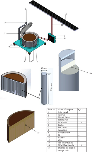
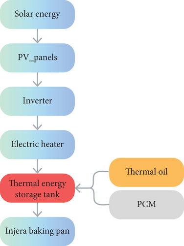
The PV was used to collect solar energy and change it to electrical energy which was then supplied to the thermal energy storage containing capsuled PCM in a cylindrical tube and thermal oil. An electric heating element was inserted at the bottom of the storage tank to increase the convective force inside the storage which produces an increase in the temperature of the fluid and PCM. Thus, the oil-PCM TES system was charged from the PV, and the reverse discharging cycle was then the PCM to oil and the oil in the storage tank to the baking pan.
The heat transfer fluid in the system was the noncirculated fluid which was working both to store sensible energy and transfer heat to the PCM inside the storage during charging; furthermore, the baking pan consists of a ceramic pan with an aluminum cover during discharging.
3. System Design
3.1. Heat Demand of Injera Baking
3.2. Baking Pan and Cover
A baking pan is a flat, circular baking dish that is typically between 50 and 60 cm in diameter. It was formerly used over big clay hearths to bake injera. In this system, an 8-mm thick and 580-mm diameter ceramic pan is selected since, compared to the clay pan or locally accessible one, it has a higher thermal conductivity. To prevent thermal loss from the system when baking and charging the storage, an insulated pan cover that is made from aluminum with a 64 cm diameter is assembled.
3.3. Selection for PCM
The choice of the eutectic, a mixture of potassium nitrate and sodium nitrate, is based on its proven potential for high-temperature cooking. The most popular thermal energy storage for solar cooking applications at the moment and the PCM that is most appropriate for this application [25, 26] is a mixture of 60% NaNO3 (sodium nitrate) and 40% KNO3 (potassium nitrate). Regarding melting points, solar salt (a nitrate salt mixture of 40% KNO3 and 60% NaNO3) is around 220°C, which has been found compatible with the temperature required on the surface of an injera baking pan [17].
Sodium nitrate (NaNO3) and potassium nitrate (KNO3) are inorganic PCMs and have a melting point of 310°C and 330°C, respectively [27, 28]. Additionally, since the melting temperature is in an acceptable range, the NaNO3–KNO3 binary mixture can be used to store latent heat for cooking purposes [5, 29].
3.4. Storage Design
| Parameter | Values |
|---|---|
| Thermal conductivity | 0.8 W/m.k |
| Density > 220°C | 1700 kg/m3 |
| Density < 220°C | 1800 kg/m3 |
| Enthalpy of fusion | 108.67 kJ/kg |
| Phase transition enthalpy | 31.91 kJ/kg |
The heat transfer fluid used in the system was thermal oil, and in addition to transferring heat in the storage, it has the capacity to store sensible energy. Typical design data for Shell Thermia Oil B heat transfer oil are summarized in Table 2 [32].
| Properties | Shell Thermia Oil B heat transfer oil | ||||||||
|---|---|---|---|---|---|---|---|---|---|
| Temp (°C) | 0 | 20 | 40 | 100 | 150 | 200 | 250 | 300 | 340 |
| Density (kg/L) | 0.876 | 0.863 | 0.850 | 0.811 | 0.778 | 0.746 | 0.713 | 0.681 | 0.655 |
| Specific heat capacity, c (kJ/kg.k) | 1.809 | 1.882 | 1.954 | 2.173 | 2.355 | 2.538 | 2.72 | 2.902 | 3.048 |
| Thermal conductivity, k (W/m.k) | 0.136 | 0.134 | 0.133 | 0.128 | 0.125 | 0.121 | 0.118 | 0.114 | 0.111 |
| Prandtl no. | 3375 | 919 | 375 | 69 | 32 | 20 | 14 | 11 | 9 |
| Coefficient of thermal expansion, β (1/°C) | 0.0008 | ||||||||
3.5. Estimation of Volume of Storage Medium (PCM)
It has been determined that the cylinder is the most practical geometry for encapsulation [33].
3.6. Material Selection
The number of cylindrical tubes made of 6061 aluminum was filled with PCM. The number of cylindrical tubes filled with PCM was 115, with 43 mm outer diameter, 1.5 mm thickness, and 250 mm length. The tube material was aluminum since it is a very good heat-conductive, available material, and applicability of the sealing idea [35]. The amount of thermal oil in the storage system was also about 25 L. Also, stainless steel was chosen as the material for the thermal storage tank because it is resistant to corrosion and high temperatures [36, 37]. The fiberglass insulation is selected for this operating temperature with the most economical thickness of 75 mm with a density of 64 kg/m3 [38] because glass fiber is good workability, is noncombustible, has low compression resistance, and many facings available also work on a temperature range of 455°C–538°C [39].
3.7. The PV System Design
The geographic location is Addis Ababa, Ethiopia.
The average daily energy consumption is 3062607kJ/day851kWh/day.
The irradiation (peak-sun hours) for Addis Ababa (from the Global Solar Atlas) is 4.607 kWh/m2/day.
By considering different losses due to shading, dust and dirt, reflection, irradiation, array mismatch, cables, inverter, and thermal losses on PV, the overall efficiency of the PV system was assumed to be 0.7 [44].
With specifications obtained from Hi-Tech [45], Table 3 illustrates the size of the PV system in watt peak for the peak load at STC for various numbers of injera.
| Number of injera | The total useful energy (kJ) | The total energy demand (kJ) | Amount of PCM (kg) | Required photovoltaic modules power PPV (W) | Number of modules | Actual photovoltaic modules power PPV (W) |
|---|---|---|---|---|---|---|
| 40 | 12760.86 | 20417.38 | 44.54 | 1231.06 | 5 | 1500 |
| 60 | 19141.3 | 30626.07 | 66.815 | 1848 | 7 | 2100 |
| 80 | 25521.73 | 40834.765 | 89.1 | 2462.12 | 9 | 2700 |
| 100 | 31902.16 | 51043.456 | 111.36 | 3077.65 | 11 | 3300 |
| 120 | 38282.6 | 61252.15 | 133.63 | 3693.18 | 13 | 3900 |
| 150 | 47853.24 | 76565.184 | 167.04 | 4616.5 | 16 | 4800 |
The inverter size depends upon the actual power needed by the system which is 2100 W. The inverter needed must be able to handle about 2100-W at 220 Vac. Therefore, we can select a Latronics inverter, which is suitable for the system; LS-2324, 2300-W, 24-Vdc, 240-Vac [46], and 2100 W electrical heating elements are connected, and these elements are in thermal contact with an oil enclosed in an insulated stainless steel cylindrical container.
4. Modeling the Baking Process Heat Transfer Mechanism of Mitad
The assumption for the analysis of an equivalent thermal circuit diagram of a PV-integrated injera baking system is that the effect of conductive heat transfer of an aluminum supporting plate on the bottom of the baking pan/mitad is assumed to be insignificant. The transfer of heat processes inside the PV-integrated injera baking system is illustrated by the thermal circuit diagram, which is shown in Figure 3.
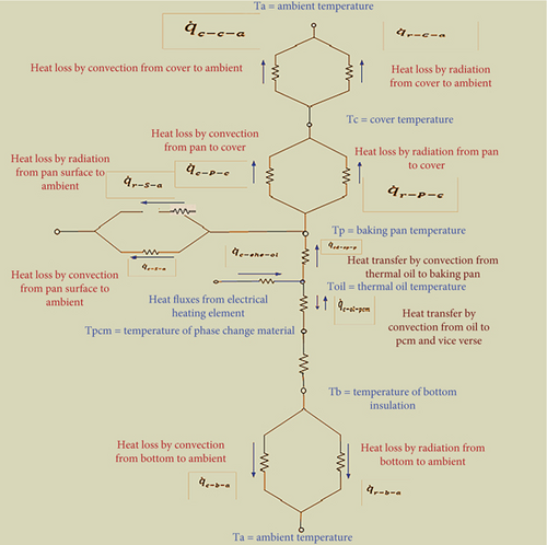
Depending on the heat transfer process shown on the thermal circuit, the mathematical model for different processes is discussed below.
5. Mathematical Model
- •
The porosity and storage arrangement remain constant.
- •
Due to the low temperature, the consideration of radiation heat transfer within the storage medium has been omitted.
- •
Conduction heat transfer within the oil has been overlooked.
- •
The heat transfer oil remains stationary, and there is no energy delivery through the heat transfer fluid from the control volume.
- •
The impact of natural convection within the molten PCM has been neglected.
5.1. Governing Equation for Molten Fraction
5.2. Governing Equation for Liquid PCM
5.3. Mathematical Model for Baking Pan
- •
The baking pan, initially covered, attains its required temperature without any initial heating-up phase.
- •
Negligible heat loss occurs through the aluminum metal, which is of very small thickness and separates the pan from the hot oil.
- •
Temperature changes exclusively occur along the thickness or in the axial direction.
- •
No heat is generated within the baking pan, and its thermal conductivity remains constant.
6. Computational Model
7. Heat Transfer Coefficient Correlations
Conduction and natural convection are two ways that heat is transferred inside the thermal storage tank. Although there is no forced velocity in the system, there are still convection currents in the fluid; these conditions are known as free or natural convection. This works when body force from the gravitational field interacts with a fluid that has density gradients caused by temperature gradients.
8. Simulation Method
Numerical simulation was conducted using a one-dimensional finite-difference computational model for thermal storage that was PCM and thermal oil, and the oil was also used as heat transfer fluid. The developed computational models are analyzed using MATLAB programming software.
The storage tank was segmented into 10 equal sections along its height, enabling the prediction of 11 axial temperatures from the bottom to the top of the tank. This division allowed for a comprehensive understanding of temperature variations along the tank’s vertical axis.
9. Initial and Boundary Conditions
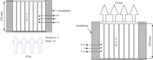
Under charging conditions, a consistent supply of heat fluxes was directed to the bottom of the storage tank, initiating the transfer of heat to the thermal oil. Subsequently, through the natural convection heat transfer process, this heat was continuously conveyed to the bottom of the PCM. Additionally, at the outset, the baking pan was securely sealed alongside the thermal storage tank. Furthermore, the baking pan was enveloped by a thermally insulated pan cover made of fiberglass. This configuration was designed to optimize heat retention and transfer within the system.
In the discharging phase, both the PCM and thermal oil released their heat to the baking pan. Notably, the surface of the baking pan was intentionally left uncovered during this process to ascertain the maximum temperature it could reach within a specified timeframe. This approach was adopted to observe and analyze the highest surface temperature achieved by the baking pan as it received the discharged heat from the PCM and thermal oil.
Boundary conditions at t > 0.
The oil-PCM storage conditions are shown in Figure 4. The schematic drawing provides a clear view of the oil-PCM storage during both the charging and discharging conditions.
10. Verification of Computational Model
Figure 5 shows a comparison of average PCM and thermal oil temperature variation using a computational model of this work and experimental test results using Duratherm 630 as heat transfer fluid, and the PCM is a binary homogeneous mixture of NaNO3−KNO3, with a molar ratio of 60:40, respectively [48]. The PCM has a mass of 11.66 kg for six cylindrical capsules with 1.08 L volume of each. The modeling was done under the same conditions as the experiment.
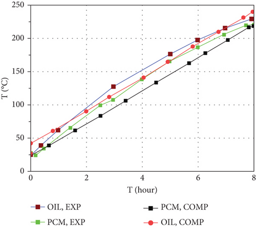
As shown in the above figure, there was a good correlation between the computational model and experimental results, and from this, we can conclude that the computational model can predict the performance of the thermal storage containing PCM and thermal oil reasonably.
11. Result and Discussion
11.1. Charging Conditions
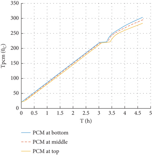
During the charging process, the transient temperature distributions within the thermal storage (oil-PCM), as well as the molten fraction of PCM and performance analyses, have been investigated. Figure 6 shows the temperature change in a PCM thermal storage that was charged using an electric heater from the PV for 4.7 h, which is the peak sun hour of the selected site, which is Addis Ababa. The temperatures reached 303.6°C and 283.4°C at the bottom and top of the PCM tube, respectively, since constant heat fluxes are supplied at the bottom of the storage. Sensible heating caused the temperature of the PCM to rise until the solid PCM began to melt; after that, the temperature remained constant and the PCM began to melt when the temperature hit 220°C. The liquefied region’s temperature rises when the PCM melts completely. After charging the storage for about 4.7 h with 2100 W, the energy stored in the system was 33 MJ.
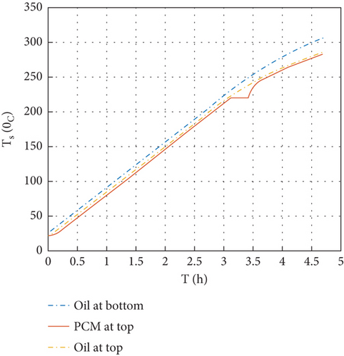
The comparison of the temperature variation of oil and PCM at the top and bottom of the thermal storage during charging for 4.7 h is shown in Figure 7.
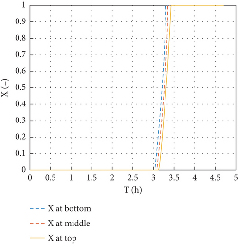
The phase change and the molten fraction variation at the top and bottom of the cylindrical tubes during the charging of the system are shown in Figure 8. PCM tubes in the storage are completely liquefied after charging for 3.425 h.
11.2. Discharging Conditions of Thermal Storage
The energy stored in the thermal storage was discharged by free or natural convection to the baking ceramic pan on the top of the storage. Initially, the baking pan is sealed with storage during charging, and the surface of the baking pan reaches its desired temperature for baking injera. The discharging analysis was conducted by assuming that the pan cover was removed and the top was directly discharged to the air for about 3 h, which is the expected time to cook the desired amount of injera. Degradation of the thermal storage’s transient temperature and baking pan surface with respect to time during discharging is shown in Figure 9.
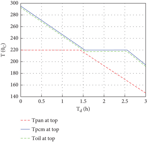
Initially, the thermal storage average temperature reached about 295°C, then the temperature of the PCM decreased until the liquid PCM reached its phase-changing temperature (220°C), then the temperature became constant and the PCM started solidifying. Because the heat transfer process was a natural convection boundary, the PCM stayed for more time to change its phase to solid, which means more latent heat is stored in the system during constant heat fluxes. The temperature continued to drop when the PCM solidified. After discharging the thermal storage for about 3 h, the temperature degraded to 194.3°C, 191.7°C, and 146.4°C for the PCM top, oil top, and baking pan top, respectively. The amount of energy discharged by the system was 16.6 MJ, and the discharging (thermal) efficiency of the system was about 50.2%. Also, the overall efficiency of the system was 46.67%.
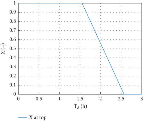
The molten fraction change at the PCM during system discharge is another indicator of the solidification of PCM thermal storage and is shown in Figure 10. The PCM began to shift its phase after discharging for 1.54 h, and all the PCM in the storage were completely crystallized after being discharged for 2.56 h.
11.3. Comparisons With Other Research
The computational result was compared with different papers as shown below.
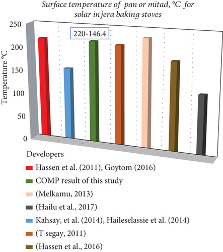
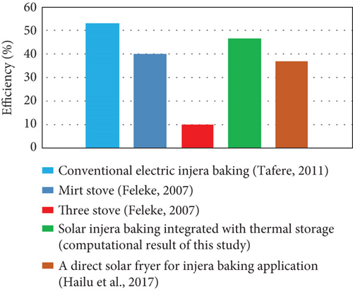
Solar-powered injera baking stoves were investigated by various researchers and have worked to achieve the average surface temperature of a baking pan around 180°C–250°C. However, from the outputs obtained by experimental work, they investigated that it was possible to use a surface temperature of a cooking pan or mitad between 120°C and 233°C, as shown in Figure 11. Also, the overall efficiency of the system was compared with different injera baking technologies, and the computational result shows that the current injera baking stove has a good performance as shown in Figure 12.
From the comparisons conducted above, the numerically investigated solar-powered injera baking integrated with thermal storage showed a promising result.
12. Conclusions
In Ethiopia, the household sector accounted for 90% of total energy consumption in 2014, while 89% of the country’s ultimate energy supply comes from biomass sources [8]. From household energy consumption, more than 50% of this energy goes entirely into baking injera. Due to its abundance as a renewable resource, solar energy is seen to be a good alternative for cooking. However, because there is a mismatch between the load and the energy available, a thermal storage system that provides the necessary energy has been integrated.
The simulation was carried out, and the storage performance was analyzed for PCM and thermia oil. The total amount of energy stored in the PCM was 23.78 MJ, and also 9.25 MJ was stored in the thermia oil.
The total amount of energy discharged from the PCM was 13.1 MJ and from the thermia oil was 3.50 MJ. Also, the baking pan surface temperature was between 220°C and 146.4°C for about 3 h, and it shows that once the system is charged, it was not fully discharged for the baking application, and it is at some amount of temperature. Therefore, we would need small hours for charging for the next day compared with the first charging hour, and we can use the energy from the PV for different household purposes like water boiling, stoves for cooking, and lighting.
Finally, it can be concluded that the numerically investigated solar-powered injera baking integrated with thermal storage showed a promising result, and to bake 60 injera traditionally, about 17875.2 g of fuel should be consumed, and it causes a very large amount of CO and particulate matter emission; therefore, this study used a clean source of energy, and it can avoid the above problem regarding the air pollution and the effect of health on females and children.
Nomenclature
-
- °C
-
- Degree Celsius
-
- HTF
-
- heat transfer fluid
-
- LHTES
-
- latent heat thermal energy storage
-
- MJ
-
- megajoules
-
- PCM
-
- phase change material
-
- PV
-
- photovoltaic
-
- TES
-
- thermal energy storage
Disclosure
The authors recognize that this research article was based on a thesis submitted to Addis Ababa University. The present manuscript is a part of my thesis submitted to Addis Ababa Institute of Technology, Addis Ababa University [49].
Conflicts of Interest
The authors declare no conflicts of interest.
Funding
No funding for this research.
Acknowledgments
The authors express gratitude for the help and guidance while working on their thesis. The authors also acknowledge the support provided by NORAD, which offered a postgraduate research fellowship during the authors’ studies.
Open Research
Data Availability Statement
Data is available upon request.


