Modeling Gas Compressor Station Operation to Minimize Fuel Costs for Surge Zone Protection
Abstract
Gas transportation through the pipeline network requires high pressure; otherwise, movement will be impossible. Due to friction with the walls of the pipes, the gas loses both speed and pressure. Therefore, it is necessary to increase the pressure in the main pipeline, which can extend for thousands of kilometers. For this purpose, compressor stations are located along the main network, facilitating the gas transport process by raising it to the required pressure. Compressor stations mainly consume the transported gas, with approximately 5% expended on gas compression. This article presents a study on the fuel cost for compressor stations, using mathematical models to optimize the operation of gas compressor units. The objective is to minimize gas consumption as a fuel and provide an optimization method with control over blower revolutions and valve installations to ensure safe transportation. Mathematical modeling of the described process detected the technically unjustified fuel gas consumption during the operation of gas compressor units at a specific compressor station under consideration. The paper proposes a method for minimizing costs, which can serve as the basis for providing recommendations to engineers-dispatchers. Compressor stations of the type under study lack measuring instruments for mass flow; therefore, the methods such as PID controllers, MPC, or neural networks are not applicable here.
1. Introduction
Natural gas is one of the world’s essential energy sources. Currently, natural gas consumption is increasing significantly [1], especially in Kazakhstan when compared to other nonrenewable energy sources. The level of gasification in the country since 2018 has increased from 49.7% to 59%. Therefore, optimizing gas transport in networks is an essential production task.
In gas transmission networks designed to collect, transport, and distribute natural gas, compressor stations are used to supply the energy necessary to overcome the friction and pressure losses in the inner wall of the pipes while ensuring the continuous flow of gas throughout the network.
However, a significant portion of the transported gas (estimated in the range of 3%-5%) is consumed by the series-parallel compressor units installed in the network before the gas reaches the receiving units. Minimizing this consumption is a task that is not only of great financial importance to the industry but also has important environmental implications. This leads to the fuel cost minimization problem (FCMP). The construction of a special model for minimizing the cost of fuel in a stationary mode is presented and used to solve the FCMP [2]. Another dynamic programming approach is presented in [3, 4].
A description of classical mathematical models describing gas dynamics can be found in [5]. Today, aided by modern, powerful computers, the numerical modeling of gas pipeline networks can be highly accurate. The development of technologies and numerical methods opens opportunities for the development of optimization methods. Over the years, researchers have tried to do this with varying degrees of success. Pipeline dispatch systems are numerical modeling and simulation of gas flow and transport behavior in pipelines, where calculated pressure and flow information is needed for decision-making (see [6]).
- (i)
Compressor stations are very complex objects; they can consist of several dozen compressor units of various configurations and characteristics; each unit can be switched on and off, and its behavior is nonlinear
- (ii)
A set of restrictions that determine the permissible operating modes of compressors, combined with restrictions in pipelines, constitutes a highly complex system of nonlinear restrictions; the aspect of antisurge protection for units is especially important
- (iii)
Operation of valves and regulators can also lead to certain problems
Considering and studying such a variety in the search for globally optimal solutions requires a deep study of its structure and operational principles.
We are solving the problem of minimizing fuel costs incurred by compressor stations. The problem of protecting the compressor from surge mode is one of the most important problems in the reliable and safe operation of compressor units (see [7]). There are many studies devoted to this problem [8, 9]. The work [10] considers the problem of calculating optimal plans for natural gas transportation from compressor stations in pipeline networks. In [11], the authors present a computationally efficient method for minimizing the cost of gas compression under dynamic conditions, when deliveries to consumers are described by time-dependent mass flow rates.
When modeling the process of gas transport, it is necessary to include linear segments of the network, i.e., pipes. The construction of pipeline models that optimize network performance is discussed in [12]. In the article [13], a simplified model of the control system is constructed for the dynamics of the flow of compressible gas through the pipeline, taking into account the distributed, time-varying injection, withdrawal, and control actions of compressors.
One approach consists of independent process controllers and antisurge controllers implemented using PI or PID controllers [14]. The process controller maintains the setpoint by controlling the torque or speed of the drive, while the antisurge controller is responsible for maintaining operation in a stable area of the compressor circuit by controlling one or more recirculation valves. The process controller usually has several operating modes, such as outlet pressure control, outlet flow control, or pressure ratio control. An advanced antisurge control, based on PID control, is proposed in [15], which was tested in protecting the compressor during fast transients of the operating point towards the surge limit line in some critical cases, such as high header pressure and low suction pressure.
- (i)
Shaft rotation speed
- (ii)
Restrictions on mass flow
- (iii)
Antisurge zone
A model predictive control was implemented to manage the operation of the compressor, incorporating antisurge protection and establishing a target compression ratio to maintain the required output pressure [17].
Recently, researchers have also been using machine learning methods to model the process of gas transport. For example, in the article [18], a dynamic modeling method based on an interpretable short-cut Elman network model (Shortcut-ENN) for a pipeline network is proposed. Deep learning methods give quite good results: [19] presents a combined approach based on an improved BP neural network for short-term gas load prediction, and the network is optimized by a genetic algorithm with real code. During the study of such problems, monitoring and optimal control of compressor operation using deep neural networks which provide intelligent control are proposed in [20, 21].
- (i)
Section 2 represents the description and statement of the problem
- (ii)
Section 3 presents a list of initial data for calculation, along with their description, fundamental equations describing the physical processes that occur during the operation of the units, and detailed descriptions of computational algorithms based on mathematical models
- (iii)
Section 3.1 encompasses all modeling problems solved numerically to build a computer model of the compressor
- (iv)
Section 4 provides a description of the main computational procedures and their relationship. The results of the calculations obtained using real data from an operational compressor station are shown in graphs
- (v)
Section 5 discusses the meaning, importance, and relevance of the research results
- (vi)
Section 6 presents a comparison with existing works (Table 1)
| The work | Inclusion in the pipeline network | Surge zone protection functionality | Using a lot of previous data | Utility/complexity tradeoff |
|---|---|---|---|---|
| Mak et al. [11] | Yes | No | Yes | No |
| Zlotnik et al. [13] | Yes | No | Yes | No |
| Amin et al. [15] | Yes | Yes | Yes | Yes |
| Torrisi et al. [17] | Yes | Yes | Yes | No |
| Zhang et al. [20] | Yes | No | Yes | Yes |
| Proposed work | Yes | Yes | No | Yes |
2. Problem Statement
Let us first provide a list of abbreviations found in the article.
The main equipment in compressor stations is a gas compressor unit (hereafter GCU given in Table 2 from [7]). The functional purpose of the GCU is to increase the pressure of the gas transported through the pipeline. The performance of this function is provided by the main components of the GCU, the engine (drive), and the supercharger. The drive can either be a gas turbine or an electric.
| GCU | Gas compressor unit |
| GCU ID | Gas compressor unit identification number |
| GTP | Gas turbine plant |
| RAR | Region of admissible regimes |
| RAV | Region of admissible values |
| ESZ | Extended surge zone |
We give a general description of the work and the scheme of the model under consideration. Centrifugal compressors belong to a subclass of dynamic axisymmetric turbomachines that absorb work [22]. The main principle of the operation of the GCU is to transfer the mechanical energy of the power turbine or electric drive to the blower impeller, which creates gas pressure.
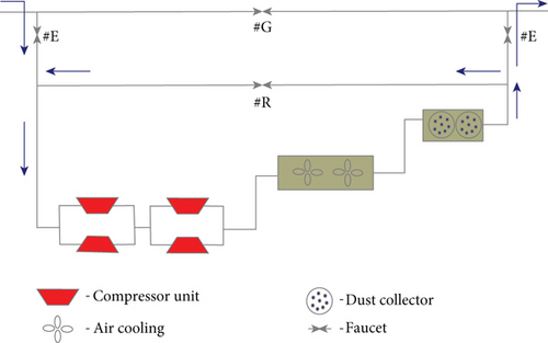
Figure 1 shows a simplified block diagram of a compressor station, which consists of 4 compressor blocks, air cooling, and a dust collector. Two pairs of compressors are connected in series, and each pair is connected in parallel. The complete scheme is much more complicated than the one presented and does not include all technological equipment. Specifically, not all pipelines and fittings that regulate the direction of the gas flow are indicated, but such a representation is sufficient for mathematical modeling of the compressor station.
The studied compressor stations are equipped with centrifugal compressors, as shown in Figure 2. There is another type of compressor often used at modern stations—reciprocating. But when modeling in the article, the first type of compressor is used because the mathematical model of operation is specific to each type.
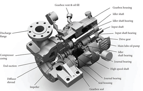
One of the main elements of the GCU is the supercharger. Its impeller contains two disks, between which there are blades that form a circular lattice. Multistage superchargers are often used, representing the sequential inclusion of single-stage wheels.
We present an optimization idea for minimizing fuel cost by adjusting the valve #R shown in Figure 1. The figure shows three types of valves installed on the compressor station pipeline, i.e., #E, #G, and #R. The valve of the first type is an inlet valve that closes when the compressor station is turned off due to a malfunction or insufficient power from other stations. The second valve is closed when the compressor station is running and participating in the network. A #R is a recirculation valve, which serves to protect the GCU from getting into the surge zone when it is opened. When the valve is fully or partially opened, a portion of the outgoing gas stream joins the inlet stream, increasing the volume of the inlet stream. The degree of valve opening is regulated and indicated by the dispatcher at the station. Blue arrows in Figure 1 show the direction of gas flow when the valve is open.
The task is to minimize the degree of recirculation valve opening by modeling the GCU load at compressor stations, thereby reducing the energy expended on compression.
3. Description of the Main Calculation
In this section, we first describe the input data used in the calculation. Next, we will demonstrate a method for constructing the tolerance range for the compressor operating point in the ε − qred plane and a method for calculating the load point to achieve the target pressure. Since the main goal of this work is to build a computer model of compressor operation to study fuel gas costs, we present the main algorithm for calculating the compression costs.
3.1. Computer Simulation Problems for Compressor Station Operation
- (i)
Calculating the region of allowable regimes, i.e., admissible limits of changes in regime and energy parameters
- (ii)
Calculating the parameters of the gas flow at the outlet of the supercharger and the regime and energy parameters of the GCU
- (iii)
Calculating the current compressor performance
- (iv)
Calculating revolutions that ensure the pumping of the gas flow with the given operating parameters
Experts in gas transportation through pipelines know within what values it is necessary to provide the main parameters of gas for the normal functioning of the pipeline. Furthermore, consumers set the range of gas indicators when received at the outlet points of the network. Therefore, in the full calculation of the main line operation, three of the listed tasks need to be solved: finding the operating mode of the compressor station to achieve the required compression, including the construction of the surge zone ((i), (iii), and (iv)).
The surge zone is the zone of unstable operation of the compressor. This zone is common to all types of compressors. During surging, the aerodynamics of the flow path deteriorates sharply, and the compressor cannot create the required pressure, while the pressure behind it remains high for some time. As a result, the reverse flow of gas occurs. The pressure behind the compressor decreases and then builds up again, but in the absence of flow, the pressure drops dramatically and the cycle repeats. During surging, the entire structure experiences large dynamic loads, which can lead to its destruction. Therefore, when constructing a calculation, it is required to know how close the operating point is to this zone, which will help reduce the risk of structural failure. The extended surge zone (hereafter ESZ) includes the area between the surge boundary and the surge control line [17].
Inlet calculations receive the gas input parameters and the required outlet pressure, which will ensure the delivery of gas to consumers with their specified characteristics.
3.2. Initial Data for Calculation
- (1)
Nameplate parameters of the drive
- (a)
Credentials
- (i)
Drive name
- (ii)
Cipher
- (i)
- (b)
Attribute
- (i)
Gas turbine
- (ii)
Electrically driven
- (iii)
Gas engine compressor
- (i)
- (c)
Nominal parameters
- (i)
Power (kW)
- (ii)
Drive (hereafter GTP (gas turbine plant) given in Table 2) efficiency
- (i)
- (d)
Restrictions for controlled drives
- (i)
Minimum shaft speed
- (ii)
Maximum shaft speed
- (i)
- (e)
State and influence coefficients
- (i)
GTP technical condition by power
- (ii)
Technical condition of GTP for fuel gas
- (iii)
Anti-icing system influence
- (iv)
Account of gas turbine operation without regeneration
- (v)
Impact of exhaust heat recovery system
- (vi)
The effect of Tair at the gas turbine inlet on the available power
- (vii)
Operating time < 25 thousand hours; 25 thousand hours < operating time < 50 thousand hours; operating time > 50 thousand hours
- (viii)
Motor efficiency
- (i)
- (f)
Cost parameters
- (i)
Nominal flow rate of GTP (103 m3/h) at rated power, as well as with the following parameters
- (1)
Gas turbine inlet air temperature Tair (K)
- (2)
Air pressure (MPa)
- (3)
Specific net calorific value (kJ/(m3·K))
- (1)
- (ii)
Gas turbine fuel consumption rate (103 m3/(kW·h))
- (iii)
Gas consumption rate for the auxiliary needs of the compressor station (103 m3/(kW·h))
- (iv)
Electricity consumption rate for the auxiliary needs of the compressor station (kW·h/(kW·h))
- (i)
- (a)
- (2)
Supercharger factory specifications
- (a)
Credentials
- (i)
Supercharger name
- (ii)
Cipher
- (i)
- (b)
Attribute
- (i)
Full pressure
- (ii)
Part pressure
- (i)
- (c)
Nominal parameters
- (i)
Rated speed
- (ii)
Nominal gas pressure at the inlet (MPa)
- (iii)
Nominal outlet gas pressure (MPa)
- (iv)
Nominal volume flow (m3/min)
- (v)
Nominal main production (106 m3/day)
- (vi)
Nominal compression ratio
- (vii)
Nominal polytropic efficiency
- (i)
- (d)
Restrictions
- (i)
Minimum compression ratio
- (ii)
Maximum compression ratio
- (i)
- (e)
State parameters
- (i)
Coefficient of the technical condition by power
- (ii)
Mechanical loss coefficient (mechanical efficiency), ηmech
- (i)
- (f)
Supercharger characteristic reduction parameters
- (i)
Compressibility factor, Z
- (ii)
Gas temperature (K)
- (iii)
Gas parameters
- (1)
Gas constant (J/(kg·K))
- (2)
Gas density under standard conditions ρst (kg/m3)
- (3)
Gas molar mass (kg/kmole)
- (1)
- (i)
- (g)
Outlet gas pressure (MPa)
- (h)
Inlet gas pressure (MPa)
- (i)
Attribute parameters
- (i)
Performance dimension for which characteristics are presented
- (1)
qred—volume normalized to nominal speed (m3/min)
- (2)
Qgen—main gas consumption (106 m3/day)
- (1)
- (ii)
Sign—power characteristic reduced to
- (1)
gas density (kW/(kg/m3))
- (2)
discharge pressure (kW/MPa)
- (3)
inlet pressure (kW/MPa)
- (4)
not listed (kW)
- (1)
- (iii)
Number of GCU revolutions for which characteristics are presented
- (iv)
Relative revolutions for which characteristics are presented
- (v)
Minimum performance
- (vi)
Maximum performance
- (vii)
Coefficients of polynomials approximating
- (1)
Pressure characteristic
- (2)
Characteristic of polytropic efficiency
- (3)
Power characteristic
- (1)
- (i)
- (j)
Gas parameters
- (i)
Gas density under standard conditions
- (ii)
Net calorific value
- (iii)
Mole fraction of carbon dioxide (CO2)
- (iv)
Mole fraction of nitrogen (N2)
- (i)
- (k)
Environment parameters
- (i)
Air temperature at the gas turbine inlet
- (ii)
Barometric pressure
- (i)
- (l)
Gas flow parameters
- (i)
Inlet pressure (MPa)
- (ii)
Gas consumption (106 m3/day)
- (iii)
Temperature
- (i)
- (a)
Here, a, b, c, d are the corresponding approximation coefficients. Examples of such landscape characteristics are shown in Figures 3 and 4.
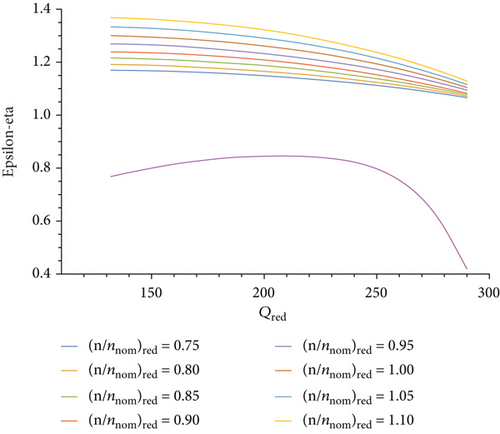
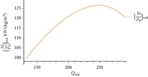
Many studies use real data to construct compressor profile maps. However, in this work, maps from manufacturers of gas compressor units were used, since the gas transport process is continuous, and stopping this process for examining and constructing new maps was not approved by “QazaqGaz” [23].
3.3. Calculation of the Region of Admissible Regimes
The construction of the region of admissible regimes (hereafter referred to as RAR) is necessary to determine the permissible boundaries of the parameters that determine the operation of the GCU. RAR can be built in different coordinates, while some of the parameters are considered independent, and some are calculated.
- (i)
GCU factory specifications:
- (1)
—calculated relative revolutions
- (2)
—volumetric reduced productivity
- (3)
—compression ratio
- (1)
- (ii)
Normative parameters:
- (1)
Kasr−dist—coefficient of distance from surge zone
- (2)
—compressor load factor
- (3)
ηmin—minimum polytropic efficiency
- (4)
—maximum discharge pressure and temperature
- (1)
- (i)
Qmin, Qmax—performance
- (ii)
—calculated relative revolutions
- (iii)
εmin, εmax—calculated compression ratio
- (iv)
—discharge pressure
The compression parameters εmin, εmax are calculated using formula (1).
Let us calculate the region of admissible values (hereafter referred to as RAV) for the revolutions and the productivity .
The RAV of the supercharger performance is determined by its factory specifications.
- (i)
- (ii)
ηmin ≤ η(qred)
- (iii)
- (iv)
- (v)
- (vi)
- (1)
Knowing the polytropic efficiency characteristic η(qred) from the constraint (ii), we find according to formula (2)
- (2)
We find the performance RAV as the area of intersection of restrictions ((i) and (ii)):
- (3)
Given that , limits ((iii) and (iv)) are written as follows:
- (4)
For any given revolutions satisfying the constraints ((v) and (vi)), one can calculate the RAV satisfying the constraints ((iii) and (iv)), or check that for these revolutions, RAV is the empty set
- (5)
The final performance RAV as a function of revolution that satisfies the constraints ((i)-(vi)) can be defined as the intersection of areas:
- (6)
In the case when at revolutions or the RAV is an empty set, then the boundaries of and should be reduced or increased accordingly until the performance RAV is found
Carrying out calculations according to the algorithm, we will get the interval for revolutions .
3.4. Optimal Control of Antisurge Protection
Optimal control of antisurge protection is implemented according to the following scheme.
-
Algorithm 1: Antisurge protection.
-
Require: Operation point {qred, ε}∈ ESZ ⊳ESZ - extended surge zone
-
Ensure:α⟵0 ⊳open degree of the valve #R
-
Δα, Δε ⊳iteration steps by α and ε
-
regime=False ⊳boolean flag
-
while α ≤ 100do
-
α⟵α + Δα ⊳increase opening of the valve #R
-
Qvol⟵Qvol + QR−valve(α) ⊳increase inlet flow volume
-
Calculate operation point {qred, ε} ⊳{qred, ε}=constructWorkPoint[Qvol, ε]
-
if operation point {qred, ε}∉ ESZ then
-
regime=True
-
break
-
end if
-
end while
-
if not regime then
-
while ε > εmindo
-
ε⟵ε − Δε ⊳reduce compression ratio by Δε
-
Calculate operation point {qred, ε} ⊳{qred, ε}=constructWorkPoint[Qvol, ε]
-
if operation point {qred, ε}∉ ESZ then
-
regime=True
-
break
-
end if
-
end while
-
if not regime then
-
Warning! It is impossible to build a stable regime.
-
end if
-
Return regime, parameters ⊳list of computed parameters is implemented in Table 3
3.5. Polytropic Work Calculation
3.6. Calculation of Fuel Gas during GCU Operation
- (i)
—individual rate of fuel gas consumption per 1 (kWt·h) of polytropic compression work (kgconv.fuel/kWt·h)
- (ii)
—nominal fuel gas flow rate (m3·103/h)
4. Results
While working on the creation of a gas transmission modeling system under the order of JSC NC “QazaqGaz,” data were obtained on the operation of most compressor stations within the gas transmission system of Kazakhstan. By examining the data and conducting calculations to model the operation of the main networks, we simulated the functioning of compressor stations according to the approaches given in the Section 3.
4.1. Basic Calculation Scheme
This subsection describes all the computational procedures that implement the calculations of the constructed method.
- (i)
Finding the boundaries of the reduced volumetric flow, i.e., determining boundaries based on the parameter of relative revolution
- (ii)
Finding the limits of relative revolutions using the reduced volumetric flow
- (iii)
Calculation of load, GCU power, and coefficient of distance from the surge zone
- (i)
Construction of the RAR boundaries using splines
- (ii)
Plotting curves for polytropic efficiency using splines
- (iii)
Construction of curves for surge zone boundaries using splines
In Algorithm 2, the operating mode construction condition is checked to see if the load point is in the RAR.
- (i)
Rspec is calculated
- (ii)
The gas compressibility factor Z is calculated
- (iii)
ρ—gas density at the entrance to the compressor unit is calculated
- (iv)
Qvol—gas volume is calculated
- (v)
The allowable power is calculated
- (vi)
The range is detected
- (vii)
Starting from , iterate over the possible values up to at a given step in order to find the optimal speed to achieve the outlet pressure
- (viii)
The limits of possible turnovers and are found from Section 3.3
- (ix)
In the found range of revolutions with a step of , the number of revolutions is selected with the condition that it does not fall into the surge zone
The computational block calculateSurgeZone[] builds surge zone boundaries. Computational procedures calculatePolytropicWork[] and calculateFuelCost[] develop the calculation of the polytropic work spent on compression at a given ε value and the fuel consumption to perform this work. Descriptions of the formulas used are given in Sections 3.5 and 3.6, respectively.
Calculations performed according to the scheme of Algorithm 2 are implemented in the Wolfram Mathematica computer algebra system, and the source code of the calculations is available here [24].
-
Algorithm 2: Calculation scheme.
-
Require: Build RAR calculation calculateRangeOfAdmissibleRegimes[]
-
Calculate operation point {qred, ε} {qred, ε}= constructWorkPoint[Qvol, ε]
-
Evaluate computational procedure calculateSurgeZone[]
-
if operation point {qred, ε}∉ ESZ then ESZ - extended surge zone
-
Evaluate procedure using Algorithm 1
-
Get regime, parameters
-
else
-
regime=True
-
Get parameters
-
end if
-
if regime then
-
Evaluate calculatePolytropicWork[]
-
Compute calculateFuelCost[]
-
Return {qred, ε}, parameters
-
end if
4.2. Implementation of the Calculation of the RAR of the Compressor Station
The following [2] template is often used to visualize the operation of a compressor. Following the accepted rules, the plotFullAdmissibleRegimesZone procedure builds a working area for the compressor based on given static and dynamic characteristics, which are described in Section 3.2.
- (i)
plotBoundaryRangeAdmissibleRegimes[]—built boundaries for the compressor workspace without surge zone
- (ii)
plotEpsilonRangeAdmissibleRegimes[]—built curves with compression ratio ε
- (iii)
plotEtaRangeAdmissibleRegimes[]—built curves indicating values of polytropic efficiency η
- (iv)
plotSurgeZone[]—built a surge zone boundaries
- (v)
constructWorkPoint[Qvol, ε]—built a work point for the compressor
After building the work area and point, we can determine the required speed to load the compressor.
Let us give an example of modeling the operation of a compressor station on a highway in Kazakhstan. Since a large load is observed on the gas pipeline transport network in winter, the study chose the period of February 2021. The plots below show the compressor operating modes on a specific day in February days both with and without recirculation. The region marked with a red-dotted line in Figures 5 and 6 represents the surge zone.
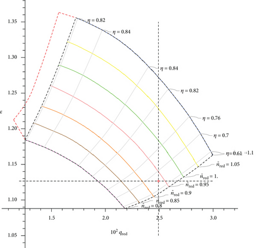
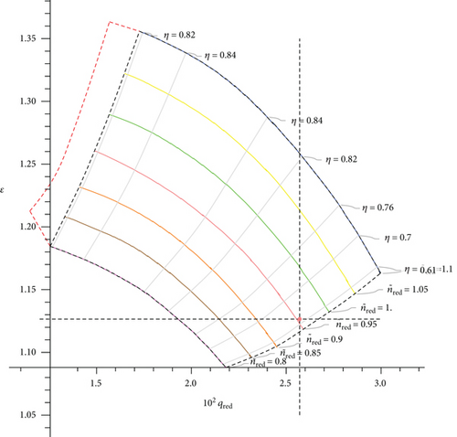
The output parameters of the computational block constructWorkPoint[Qvol, ε] are the following values for Figures 5 and 6, shown in Table 3.
| Calculated rotations | 5035 | rot/min |
| Real rotations | 5000 | rot/min |
|
|
0.9401 | — |
| ηpol | 0.6676 | — |
| Tout calculated | 13.3783 | °C |
| Tout real | 15 | °C |
| Nred | 124.671 | — |
| Navailable | 4887.5 | kW |
| Ninner | 2495.96 | kW |
| Kcharge | 0.5629 | — |
| Kdist | 1.8642 | — |
| N | 2751.13 | kW |
| Qfuel−gas | 1557.31 | m3/hour |
| Compressor work point X | 249.677 | — |
| Compressor work point Y | 1.1265 | — |
| Calculated rotations | 5107 | rot/min |
| Real rotations | 5000 | rot/min |
|
|
0.9535 | — |
| ηpol | 0.6245 | — |
| Tout calculated | 14.108 | °C |
| Tout real | 15 | °C |
| Nred | 123.945 | — |
| Navailable | 4887.5 | kW |
| Ninner | 2588.72 | kW |
| Kcharge | 0.5838 | — |
| Kdist | 1.8925 | — |
| N | 2853.37 | kW |
| Qfuel−gas | 1596.53 | m3/hour |
| Compressor work point X | 257.073 | — |
| Compressor work point Y | 1.1265 | — |
Table 3(a) contains compressor loading parameters for date 02.01.21 at 02:00, and Table 3(b) contains the same parameters for the same date and time but with #R valve opening. Due to the increase in the volume of gas entering the compressor as a result of the valve opening, the number of revolutions was increased from 5035 to 5107—in order to maintain the compression ratio. As the load on the unit increased, the amount of fuel gas for compression also increased from 1557.31 to 1596.53 (m3/hour). It is important to note that there are situations when opening the valve is necessary, for example, in case of insufficient volume of incoming gas.
4.3. Implementation of Optimal Control of Antisurge Protection
In the constructed method outlined in the Section 3.4, two cases were examined using Algorithm 1. Below, we present the calculation results.
Case 1. The case in which the opening of valve #R is sufficiently.
Here the third dimension denotes the number of GCU revolutions.
In the first case shown in Figure 7, the operating point of the GCU fell into the ESZ. Therefore, the graph shows the implementation of the enabled antisurge protection solution mode using only valve #R. The orange lines represent intermediate steps indicating the number of revolutions, while the green point indicates entry into the stable zone and recommended parameters for protecting the compressor.
Case 2. The case in which the opening of valve #R is not sufficiently.
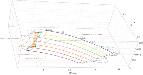
In the second case shown in Figure 8, the operating point of the GCU fell into the surge zone. The graph demonstrates the implementation of the enabled mode for solving antisurge protection using valve #R and reducing the compression ratio.
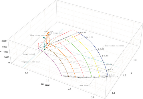
It is important to note that both cases can be addressed by Algorithm 1, allowing for dynamic feedback.
4.4. Fuel Gas Cost Result Analysis
Fuel gas is consumed from the transported gas, as mentioned above, and is a controlled parameter depending on the number of revolutions and the volume of compressed gas.
Section 3.1 contains a description of the surge zone; if the GCU enters this zone, it does not work correctly and prolonged exposure to this zone can lead to its destruction. To protect structures from surging, a common practice involves increasing the volume of gas processed by the GCU by opening the valve #R.
During calculations for one of the winter months for one gas pipeline, it was found that the valve was fully or partially open for about 85% of the entire time of the station’s operation. This value is very high, so there is a natural desire to make the opening of the valve optimal in terms of minimizing fuel gas consumption, provided that the compressor is kept in a safe working area.
The initial data for calculation, as described in Section 3.2 were conditionally divided into static and dynamic parameters: all characteristics of the compressor and drive were classified as static, while dynamic indicators included ambient temperature, main indicators of the input gas flow, such as pressure, temperature, volumetric velocity, data from laboratory studies of gas, etc.
The simulation period was taken as December 2021. Dynamic parameters were taken every 2 hours per day, including real output gas flow data. The calculations were performed on Intel Core™ i7-7700HQ CPU 2.80 GHz×8 processor and took 24.4 seconds of time for one day.
Figure 9 shows the calculated curves: on the ordinate axis, the value of fuel gas in (m3/hour), and on the abscissa, the simulation time. Vertical lines separate the calculation days.
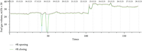
The green line indicates fuel gas consumption without recirculation, and the brown line indicates consumption with recirculation.
Let us focus on the calculation area where the construction of the regime was impossible.
In Figure 10, the calculation fell at four points in the period 12/17/2021-12/19/2021. Without opening the valve, the safe mode cannot be built at the selected points. In the calculation, the loading point of the unit falls into the surge zone, so the recirculation mode must be turned on in these cases.
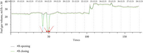
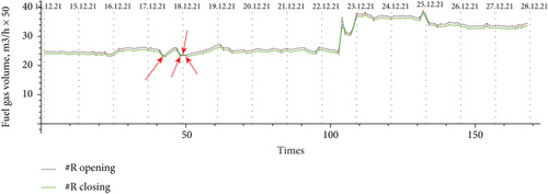
Figure 11 demonstrates how the calculation not only preserved the unit but also determined the optimal load for the compressor station based on the specified parameters of the inlet gas flow. To find the optimal load of the gas compressor unit, the degree of valve opening is calculated for a given step at the interval [0, 1]. At each point in Figure 10, the constructWorkPoint[Qvol, ε] procedure is executed enumerating the degree of the valve opening.
It should be noted that the calculation does not include the consumption of fuel gas for cooling the output stream after compression and the operation of dust collectors. The heated gas is cooled before being sent to the pipeline to prevent condensation of moisture in the pipes and is purified to protect the pipes from contamination. The recirculation process noticeably increases the temperature of the gas stream, and therefore, the load on the cooler increases.
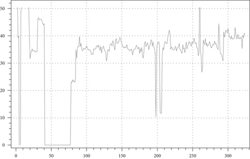
To provide an understanding of the fuel gas consumption volume at the compressor station, below are graphs in comparison with and without optimization (see Figures 12 and 13). According to the results of mathematical modeling for compressor operation with the goal of minimizing fuel gas cost, it was possible to reduce the consumption by 41905.8 m3.
5. Discussion
The proposed methodology is applicable in cases where calculating a dynamic system is challenging due to incomplete input data. For example, in the type of compressor stations under consideration, there is a lack of measuring instruments for mass or volume flow. Calculations are only feasible over extended periods, specifically every 2 hours. During these intervals, information is received from natural gas suppliers and fields regarding the volume of gas entering the pipeline that traverses the compressor stations under study. To ensure antisurge protection of units, dispatchers regulate or control the state of recirculation valves. Without the necessary calculations, such actions can lead to an irrational solution.
For optimal control of antisurge protection, it is necessary to build the operating mode of compressors and calculate the distance from the load point to the surge zone. This approach ensures fuel gas savings when opening the valves that control the inlet flow.
In such cases, it is possible to check for fuel gas “leakage” at intervals, indicating irrational use of resources and detecting an unreasonable degree of valve opening. The only way to detect this is to implement all the calculations given in Section 3.1 and apply the algorithm for minimizing fuel costs described in Section 3.4.
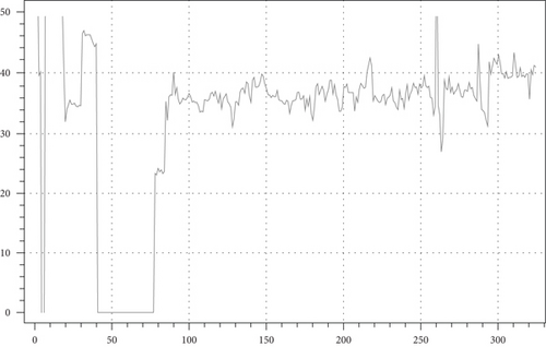
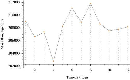
According to the contracts between gas supply companies and purchasers, the mass flow is expected to be supplied in a stationary mode. However, in reality, the volume of gas exhibits dynamic changes. Figure 14 shows a schedule of gas supply changes from one field during a single day. PID controllers in automatic control systems effectively generate a control signal to achieve the required accuracy and quality of the transient process and show good results when the process is close to stationary. However, when there are substantial changes in the parameters of the controlled process, the nonlinearity and nonstationarity of the system present significant challenges.
Future studies are aimed at enhancing this methodology by integrating direct calculations with deep learning methods to identify gas compressor unit parameters. This approach seeks to reduce reliance on empirical data for calculations.
6. Comparison with Existing Works
Let us compare the proposed algorithm with existing works. Please see the comparison results in Table 1.
7. Conclusion
During this study, a fuel gas leak was detected due to the suboptimal use of the #R valve. To confirm the hypothesis, most of the characteristics of the operating equipment at the compressor station and the necessary gas indicators, which were taken from the meters by specialists at the station, were used. The mathematical modeling of the gas compression process enabled us to evaluate leakage and provide recommendations for optimal fuel gas consumption. Figure 12 shows the graph of gas consumption during the simulated period based on real data of the compressor station, while Figure 13 presents the calculation results including the optimal valve opening values for the points from Figure 10.
Figure 12 contains sections with zero values; for these points, calculating the load from the RAR was hampered by “bad” input parameters, namely, the mass flow was almost 1.5 times lower than the allowable level. It is assumed that in these days, gas reserves from special reservoirs were used. Although the temperature of the inlet stream is high, as registered by the sensors, which indicates the complete and extended opening of the recirculation valves, the temperature during this period fluctuated in the range of 10–30°C. This was in contrast to the normal conditions for December, where it is typically around 4–5°C. Such issues often arise when working with real data from practical GCU operations, although they are theoretically considered impossible.
In the future, it is planned to investigate and develop a model for the gas transport process in the pipeline network including compressor stations.
Conflicts of Interest
The authors declare that there is no conflict of interest regarding the publication of this paper.
Acknowledgments
This research is partially supported by the Science Committee of the Ministry of Science and Higher Education of the Republic of Kazakhstan (Grant Nos. AP14869558 and AP14871523).
Open Research
Data Availability
Data are available from the following: https://github.com/zhus-dika/math_modelling_compressor_unit.


