Dynamics and Control of Noncooperative Space Target Capture Using a Flexible Manipulator
Abstract
The capture of noncooperative space targets is an important research topic in the aerospace field. Although a lot of research has been done, capturing remains a significant challenge, particularly when using a flexible manipulator. In this paper, the dynamic modeling and control problems of capturing a noncooperative spacecraft using a long-span flexible manipulator are investigated. Firstly, a modified model is presented to describe the flexibility of the manipulator arising from both its links and joints, in which the flexibility of the joint is considered as an elastic constraint of links. Additionally, we provide the frequency and mode functions of this model and derive the dynamic equations of the flexible manipulator based on the floating frame of reference formulation. Secondly, this paper employs the position–based damping control method to design the capturing controller. A simulation example of capturing a tumbling spacecraft in three dimensions is presented. The simulation results show that the designed control method can quickly eliminate vibration and achieve stable contact retention for at least 3 s when capturing noncooperative spacecraft.
1. Introduction
A space station, an advanced facility positioned in outer space, functions as a pivotal center for scientific research, international collaboration, and exploration beyond Earth’s atmosphere. To ensure its uninterrupted long-term operation, the space station requires regular resupply missions conducted by various spacecraft, including unmanned cargo spacecraft equipped with fully autonomous docking systems. In the event of failures during autonomous docking, the cargo supply mission will be unable to be completed, necessitating a relaunch to provide the space station with the necessary supplies. Utilizing the space station’s long-span flexible manipulator for capturing a malfunctioning cargo spacecraft holds significant economic value. Yet, this task presents significant challenges due to the risk of collision during the capture operation. Such an impact could disengage the target from the capture effector and potentially cause damage to the flexible manipulator. Therefore, further research into controlling flexible space manipulators for safe and efficient on-orbit capture tasks is imperative.
Flexible space manipulators are pivotal in on-orbit assembly, testing, and maintenance, with notable examples being the shuttle and International Space Station arms (Canadarm and Canadarm 2) [1]. Their flexibility arises from lightweight links and joints, posing challenges such as reduced accuracy and excessive vibrations [2], particularly in capturing noncooperative targets. Scholars have extensively investigated the dynamics modeling and simulation of flexible spacecraft manipulators during the capturing process. For instance, Cyril et al. [3, 4] delved into postcapture dynamics deeply. Kövecses and Cleghorn [5] introduced an impulsive constraints-based approach to describe capturing impact, utilizing Jourdain’s principle to derive dynamic equations. Liu, Wu, and Lu [6] researched the impact dynamics and control of a flexible dual-arm spacecraft capturing an object, revealing substantial impact effects on system dynamics when capturing objects at specific velocities. Felicetti et al. [7] utilized ADAMS to build a capture dynamic model. Yu et al. [8] proposed a simplified model for simulating flexible manipulators to analyze capturing impact. Wei et al. [9] investigated an adaptive model-free constrained prescribed performance control approach for flexible spacecraft with unknown captured objects, considering various complexities such as elastic vibration and external disturbances. Stolfi, Gasbarri, and Misra [10] derived a dynamics model for a two-arm flexible space manipulator system with nonlinear formulation for the rigid-body motions and linear for the elastic dynamics. Additionally, Ma et al. [11] proposed a parametric modeling method for flexible space manipulators and analyzed their dynamic behavior during the docking and capturing process.
The research reviewed above shows that the impact of capturing can generate significant adverse effects to the capturing task. To reduce these adverse impacts, various methodologies and strategies have been proposed. For instance, Yoshida et al. [12–14] introduced an impedance match control method based on conventional impedance control to prevent the grasper from moving away after collision. Their approach involves adjusting collision behavior by manipulating collision mass. Uyama et al. [15, 16] proposed a modified impedance control method, aiming to set the coefficient of restitution to zero by controlling the relative motion between the end-effector (EE) and the target. Stolfi et al. [17, 18] augmented the EE with a compliant wrist to mitigate collision impact and employed an impedance controller to drive the robotic arm. In contrast to Uyama et al.’s research [16], the compliant wrist was utilized specifically to prolong contact duration. Moreover, Flores-Abad et al. [19] introduced a disturbance-observer–based impedance controller to extend contact time during capturing, demonstrating enhanced controller robustness against uncertainties through simulation results. Wu et al. [20] developed a generic frictional contact model and designed a resolved motion admittance control method to realize tracking for a tumbling target. Han et al. [21, 22] proposed a dual-integral sliding mode (DISM) control method based on the reconfiguration of the reaction wheels and designed a compliant controller to ensure stability in the contact force of a dual-arm spacecraft. Wang et al. [23] adapted the hybrid force/position controller to manage contact force during the capture task. Furthermore, Raina et al. [24] used an adaptive reactionless control strategy for capturing objects with unknown parameters after the impact. In our prior works [25, 26], we proposed two damping control methods to reduce the collision impact effect and analyzed the dynamic behaviors of rigid spacecrafts during capture tasks.
In the aforementioned research, scholars have proposed diverse control methods aimed at enhancing capturing success by mitigating collision impact. However, while these methods have been shown to be effective for capturing tasks using a rigid manipulator, their suitability for use with a flexible manipulator remains unanswered. Although some researchers, such as Cyril, Jaar, and Misra [27] and Liu, Wu, and Lu [6], have studied the capturing control problem using a flexible manipulator, the capturing object they only considered is a floating lightweight cylinder. Obviously, when the captured object is a floating spacecraft, the difficulty of control will increase significantly. Given the importance of the capture task using a flexible manipulator, this paper studied the dynamics and control problems of that task in depth. Firstly, a modified model is introduced to characterize the flexibility of both the link and joint, where joint flexibility is considered an elastic constraint of the links. The model’s frequency and mode are outlined, establishing the dynamic equation of the flexible manipulator based on the floating frame of reference formulation. Subsequently, this paper designed a position–based damping–capturing controller for the flexible manipulator. Finally, diverse simulations are executed to assess the efficacy of the designed controller and analyze the influence of control parameters on performance.
The structure of this paper is organized as follows: Section 2 briefly introduces the dynamic modeling of spacecraft and capture, including the use of an improved modeling method of a flexible joint link manipulator. In Section 3, a position–based damping control algorithm is described, and the overall strategy and related mathematical principles are presented. In Section 4, several numerical results are given, and the parameter selection and performance are analyzed. Section 5 reports the final conclusions.
2. Dynamic Modeling of a Flexible Space Manipulator
In this paper, the flexible space manipulator refers to the long-span manipulator, whose flexibility mainly comes from lightweight links and joints. In previous studies focused on capturing dynamics, the consideration has mainly been on the flexibility of the links, neglecting the joint’s flexibility. However, Ma et al.’s work [11] has demonstrated the impact of joint flexibility on the manipulator’s dynamic behavior during capturing. For a more accurate simulation of real capturing conditions, it is essential to incorporate both link and joint flexibility in the dynamics modeling.
2.1. Description of Capturing System
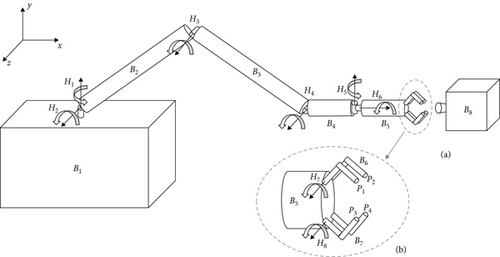
In this paper, we employ the capturing system shown in Figure 1 to study the dynamics and control of capturing a noncooperative spacecraft using a flexible manipulator. As depicted in Figure 1, the capturing system consists of a base, a long-span manipulator, and a free-floating noncooperative spacecraft. The long-span manipulator includes two flexible links (B2 and B3) and two rigid links (B4 and B5). The joints of the manipulator are revolute joints, and only the flexibility of Joint 2 (H2) and Joint 3 (H3) are considered. This section addresses the dynamics modeling problem by initially introducing a modified link model that accounts for the flexibility of both links and joints. Here, joint flexibility is treated as an elastic constraint of the flexible link. The utilization of this modified flexible link model reduces the number of variables and facilitates the analysis of vibration effects during capturing. Subsequently, we establish the dynamic equation of the flexible manipulator using the floating frame of reference formulation. This equation integrates the mode of link flexibility to describe the contribution of deformation. Further details regarding this modeling approach will be provided in the following sections.
2.2. Description of a Flexible Link With a Flexible Revolute Joint
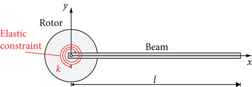
In most research on the dynamic modeling of the manipulator with the flexible link and flexible joint, the flexibility of the link and joint is considered separately. The flexible link is regarded as a deformable cantilever beam, and the flexible revolute joint is represented by a real revolute joint and a virtual revolute joint with a torsional spring. The latter joint is used to represent the joint flexibility. According to the structural dynamics theory [28], however, the introduction of a virtual revolute joint with a torsional spring is unnecessary, and the elastic constraint can describe the joint flexibility. Hence, the flexible link connected with a flexible revolute joint can be simplified as a supported-free deformable beam with an elastic revolute constraint as shown in Figure 2. Since this study employs the assumed mode method to describe the contribution of flexibility to the dynamics of the capturing system, we present the mode function of the modified flexible link in this subsection.
For clarity, notations (∗)′ = ∂(∗)/∂x, (∗)′′ = ∂2(∗)/∂x2, (∗)′′′ = ∂3(∗)/∂x3, (∗)(4) = ∂4(∗)/∂x4, , and are used throughout this paper.
As a result, the mode functions (Equation 15) and the natural frequencies (Equation 14) of the flexible beam with an elastic constraint have been obtained.
2.3. Dynamic Modeling of Capturing System
As shown in Figure 1, the capturing system consists of a service spacecraft with flexible manipulators and a noncooperative spacecraft. This study employs the multibody dynamic method based on the floating frame [29] to model the dynamic equation of the capturing system. The L-N model [30] is used to describe the collision force between and manipulator and the noncooperative spacecraft.
This formula is the dynamic equation of a multibody system. The derivation details can be found in our previous work [31].
3. Capturing Control
In the process of capturing, the grasper of the manipulator inevitably collides with the surface of the noncooperative spacecraft. The impact of collision could push the grasper away from the target spacecraft. Avoiding this situation is a prerequisite for completing the capturing mission. In order to address this issue, scholars proposed various control methods for operating the manipulator. However, it is noteworthy that the effectiveness of these methods has primarily been demonstrated on short-span rigid–type manipulators. Until now, few studies have focused on the capturing control of the long-span flexible manipulator. In this study, we employed the position-based damping control scheme to design the capturing controller, which was proposed for the rigid manipulator in our previous work [25, 26]. The control objective of the position–based damping control scheme converts the manipulator into a damper. Consequently, the impact of collision on the grasper will be absorbed by the manipulator during capturing. Meanwhile, the reactive force acting on the grasper will prevent it from moving away from the noncooperative spacecraft. As shown in Figure 3, the position–based damping control scheme primarily comprises a damping motion planner and a motion controller. The role of the damping motion planner is to generate the desired trajectory for the grasper incorporating damping forces. Meanwhile, the motion controller is responsible for guiding the manipulator to ensure that the grasper accurately follows the specified trajectory. Generating the desired trajectory for the grasper is the key issue of the position–based damping control scheme, which determines whether the manipulator can be converted to a damper. Next, this section will present the details of the motion planner and the motion-tracking controller.

During capturing, , , , and are expected to equal to ygrasper(0), , zgrasper(0), , respectively. And the direction cosine matrix of the grasper in the body-fixed frame of the noncooperative spacecraft is expected to equal to Agrasper(0). Moreover, the position and orientation of the service spacecraft are expected to remain unchanged. After the motion of the noncooperative spacecraft is obtained by sensors, such as cameras or lasers, the inverse kinematics of the manipulator, ignoring its own flexibility, is employed to its desired motion in the joint space.
Compared to classical CTM, the DOB controller can compensate for this flexibility as a disturbance term in the control, thereby improving the performance of the controller to a certain extent. The effectiveness of the controllers was compared in Section 4.3.
4. Numerical Results
In this section, numerical simulations are carried out to verify the correctness of our dynamic modeling method, evaluate the effectiveness of the damping control scheme, and provide a detailed analysis of its performance.
4.1. Simulation Settings
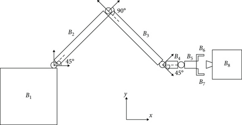
The structures of the service spacecraft and the noncooperative spacecraft are shown in Figure 1 before, while their physical parameters are presented in Table 1.
| Body | Mass (kg) | Ixx (kg·m2) | Iyy (kg·m2) | Izz (kg·m2) | EI (N·m2) | GJ (N·m2) | EA (N) |
|---|---|---|---|---|---|---|---|
| B1 | 1 × 10⁵ | 5 × 10⁶ | 5 × 10⁶ | 5 × 10⁶ | |||
| B2 | 138 | 0.397 | 470.90 | 470.90 | 4.04 × 10⁶ | 2.040 × 10⁶ | 2.8 × 10⁹ |
| B3 | 138 | 0.397 | 470.90 | 470.90 | 4.04 × 10⁶ | 2.040 × 10⁶ | 2.8 × 10⁹ |
| B4 | 18.38 | 0.023 | 0.149 | 0.149 | |||
| B5 | 18.38 | 0.023 | 0.149 | 0.149 | |||
| B6 | 1.486 | 1.5 × 10⁻² | 9 × 10⁻³ | 9.8 × 10⁻³ | |||
| B7 | 1.486 | 1.5 × 10⁻² | 9 × 10⁻³ | 9.8 × 10⁻³ | |||
| B8 | 2000 | 300 | 350 | 250 |
The lengths of the bodies B2–B5 are 6.4, 6.4, 0.3, and 0.3 m, respectively. The base B1 and the target spacecraft B8 are cubes with sides of 1 and 0.5 m. The sample time of control is 5 ms. As initial conditions, the manipulator of the spacecraft is already deployed which joint angles are chosen as . The initial position and attitude of the target are shown in Figure 4. The center of the grasper mass is aligned along the x inertial axis with the target center of mass. During the collision control phase, the grasper is locked at 90°. After this phase, the spacecraft state stabilizes, and the grasper begins to close.
4.2. Dynamic Model Verification
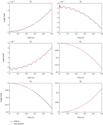
To validate our modified dynamic model, we conducted a numerical simulation using both Adams and our proposed method. In this simulation, torque is applied to the joints to alter the configuration of the space manipulator. Initially, the entire capturing system is static, with the manipulator set at initial joint angles of . Constant driving torques are applied to each joint, given by fey = [500 N · m,−500 N · m,−100 N · m,−10 N · m, 0.5 N · m, 0.1 N · m]T. The time histories of rotation angles for each joint, calculated using both our method and Adams, are depicted in Figure 5. It is evident from the figure that the simulation results of our model align with those obtained from Adams, affirming the validity of our proposed model.
4.3. Effectiveness of the Position–Based Damping Control
In the simulation case, the translational velocity components with respect to the inertial reference frame are assumed as [−0.2 m/s, 0, 0]T with an angular velocity around its center of mass of [0, 0, −0.1 rad/s]T shown in Figure 6. The applicable damping coefficient is C = 4000, and the control parameters of the motion controller are chosen as Kp = diag(40,40,40,40,40,40) and Kd = diag(25,25,25,25,25,25). Given that the problem of flexible manipulator capture is still in the research phase and there is no consensus on the optimal material for end effector design, we use the contact stiffness kc = 1 × 10⁶ N · m–1.5 and the collision coefficient of restitution e = 0.8 in this section to preliminarily evaluate the effectiveness of the control strategy and assess whether the introduction of the new DOB motion tracking control can improve performance. In Section 4.5, we will simulate captures using various contact stiffness values to further evaluate the operational boundaries of the capture control strategies. The results of this research can provide valuable references for the design of end effectors.
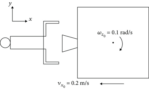
Figure 7 shows that when the servicing spacecraft is not controlled, the contact time is very short, only about 70 ms (note: a positive penetration depth indicates there is contact, while a negative or zero value means there is no contact). In contrast, when the service spacecraft is controlled with both CTM and DOB controllers, the contact time of all grasper contact points is significantly extended to at least 3 s as shown in Figure 8, indicating that the damping control scheme prevents separation from the target, effectively forming a stable contact after the collision. Meanwhile, after using the DOB controller, the contact oscillation of the upper gripper was significantly reduced, and the contact depth was more consistent with that of the lower gripper, indicating that the attitude control effect of the gripper has been improved. Therefore, the numerical simulations in the following sections are all based on the DOB controller. The DOB gain is set as 5.
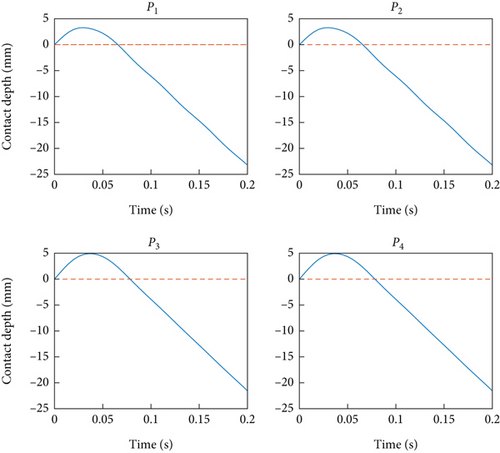
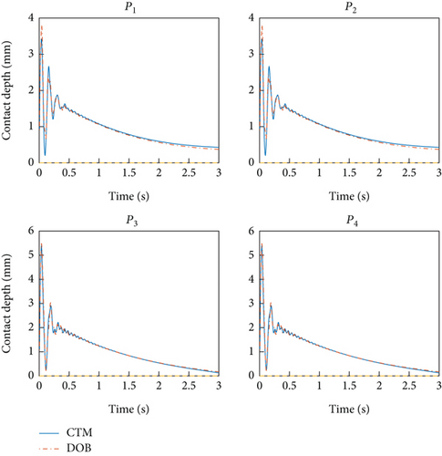
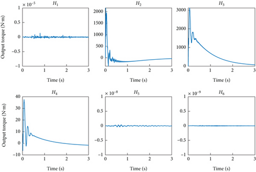
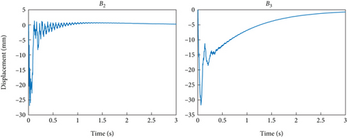
Figure 9 shows the control torque used in the damping control scheme, with a maximum torque not exceeding 3000 N·m and a rapid decrease over time, indicating that our method can achieve control at a controllable energy cost. Figure 10 depicts the vibration of the end of the flexible manipulator in the y-direction. After the collision, the robotic arm will produce relatively obvious vibrations, but after using the damping control scheme, the vibrations will be significantly suppressed and become stable. Considering that the flexible arm is 6.4 m long, subsequent vibrations are negligible.
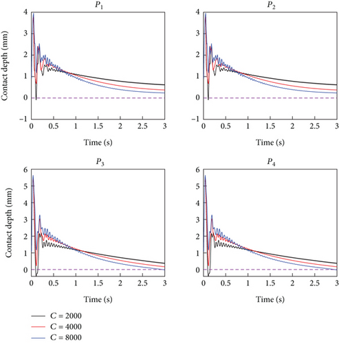
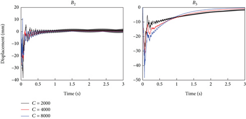
The above simulation results have verified the effectiveness of the proposed control scheme. Next, three new simulations are conducted to evaluate the impact of different control damping coefficients on the control results. Here, we take three damping coefficients of 2000, 4000, and 8000 as examples. Except for the damping coefficient, all other parameters are consistent with the above simulations. As shown in Figure 11, a smaller damping coefficient results in a shorter duration of separation but can achieve a longer contact duration. In contrast, larger damping will increase the duration of oscillation. Figure 12 shows that as the damping increases, the vibration duration of B2 and B3 decreases, the initial vibration amount of B2 decreases, and the initial vibration amount of B3 increases, both of which are controllable. In summary, the damping coefficient has little effect on the overall effectiveness of the control scheme. Our method has high parameter adaptability and can achieve good control effects on the system over a large range.
4.4. Influence of the Manipulator’s Flexibility Manipulator on the Control
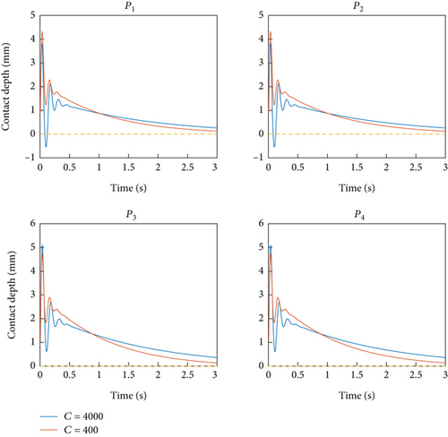
This section will carry out two sets of simulations to illustrate the influence of the manipulator’s flexibility on the control outcomes. The simulations involve the operation of the same controller on both a rigid manipulator and a flexible manipulator to accomplish the capture task. The inertia parameters and geometry parameters for the rigid manipulator are identical to those of the flexible manipulator. In the first set of simulations, the damping control coefficient C is set to 400, while the motion control parameters Kp and Kd are chosen as diag(500,500,500,500,500,500) and diag(300,300,300,300,300,300). In the other set, all control parameters remain the same as those in Section 4.3. Figure 13 shows that the rigid manipulator can stably contact the target after a collision under different control parameters. However, Figure 14 shows that the flexible manipulator can only stably contact the target when C is larger and Kp and Kd are smaller. These results indicate that controlling the flexible manipulator is more challenging and highlight the necessity of choosing larger C and smaller Kp and Kd to effectively control the flexible manipulator.
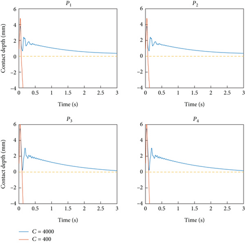
The analysis of the damping control [26] indicates that the effective mass involved in collisions affects the damping control gain. Specifically, as the effective mass decreases, the required damping control gain increases. This is because a reduction in the effective mass of the space robot makes the EE more susceptible to being pushed away by collision forces. To counteract this tendency, the space robot must apply greater control to the EE, necessitating a higher damping control gain. Unlike rigid space manipulators, flexible space manipulators deform and absorb impact energy upon collision. This deformation can be modeled as a spring connecting the base and the EE, meaning the base does not fully engage in the collision. Consequently, the effective collision mass of a flexible space robot is smaller than that of a rigid one. This explains why a larger damping control gain is required when using a flexible manipulator to capture a noncooperative object.
Additionally, due to the influence of deformation, the response of a flexible manipulator is slower compared to that of a rigid manipulator under the same control force. Therefore, using large Kp and Kd parameters can significantly increase overshoot, leading to substantial oscillations in the system. To achieve better control results, it is necessary to use smaller Kp and Kd values when controlling a flexible manipulator.
4.5. Robustness of the Damping Control Scheme to Uncertainty
In the actual capture mission, the inertial parameters of the target and initial collision conditions of the captured target may not be accurately known. Hence, whether the damping control scheme can maintain robustness under different conditions deserves further analysis.
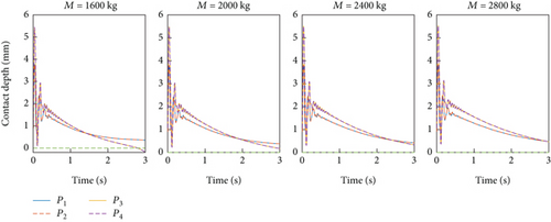
Initially, we assess the robustness of the damping control for different target inertia parameters outlined in Table 2. The remaining simulation settings align with those described in Section 4.3. As depicted in Figure 15, our damping control scheme effectively establishes stable contact between the grasper and different targets using the same control parameters, even in the presence of varying inertia parameters. This observation underscores the robustness of the damping control scheme in mitigating uncertainties related to the target’s inertia parameters.
| Case | Mass (kg) | Ixx (kg·m2) | Iyy (kg·m2) | Izz (kg·m2) |
|---|---|---|---|---|
| 1 | 1600 | 250 | 300 | 200 |
| 2 | 2000 | 300 | 350 | 250 |
| 3 | 2400 | 350 | 400 | 300 |
| 4 | 2800 | 400 | 450 | 350 |
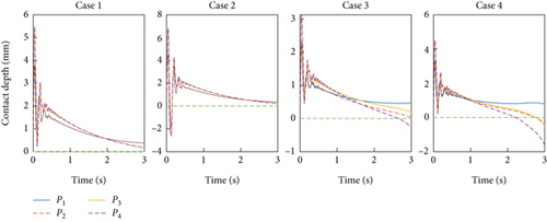
The second set of simulations explores different initial target velocities, as indicated in Table 3. The other settings are the same as those in Section 4.3. The results shown in Figure 16 indicate that the control strategy successfully extended the contact duration of the target in various initial states to varying degrees, although there may be brief separation phenomena. This observation highlights the robustness of the damping control scheme in the face of uncertainties in the target’s initial velocity, without necessitating alterations to the control parameters.
| Case | vx (m/s) | ωx (rad/s) | ωy (rad/s) | ωz (rad/s) |
|---|---|---|---|---|
| 1 | −0.2 | 0 | 0 | −0.1 |
| 2 | −0.24 | 0 | 0 | −0.12 |
| 3 | −0.1 | 0.01 | −0.01 | −0.05 |
| 4 | −0.15 | 0.02 | −0.02 | −0.1 |
The third set of simulations involves different contact stiffness coefficients: 1 × 10⁵, 1 × 10⁶, and 1 × 10⁷. The remaining settings are consistent with those outlined in Section 4.3. Figure 17 illustrates that, when the contact stiffness is less than 1 × 10⁷, the contact rapidly stabilizes, preventing separation between the grasper and the target. As the contact stiffness becomes 1 × 10⁷, the initial stage shows more noticeable oscillations in contact depth, indicating that the grasper and the target experience a “contact-separation” state. Despite this, after multiple occurrences of contact separation, the controller establishes stable contact between the grasper and the target, prolonging the contact duration. Thus, without changing the control parameters, the results in Figure 17 demonstrate the robustness of the damping control scheme to the uncertainties of the contact stiffness.

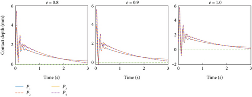
In the final set of simulations, various coefficients of restitution were considered. The results of these simulations are presented in Figure 18. As depicted in the figure, it is evident that, without altering the control parameters, the damping control scheme can consistently achieve the control objectives across different coefficients of restitution.
5. Concluding Remark
In this paper, we investigate the dynamic modeling and control challenges associated with capturing a noncooperative spacecraft using a flexible manipulator. We introduce an improved modeling method tailored for a flexible link with a flexible revolute joint. This approach accounts for joint flexibility without adding extra degrees of freedom, thereby improving solution efficiency and simplifying controller implementation. Subsequently, we apply a position–based damping control scheme to address control challenges. Significantly, the control scheme, originally devised for rigid manipulators, is extended to accommodate the flexibility of the manipulator. Numerical simulations are conducted to assess the efficacy of the modified dynamics modeling method and the adopted control scheme. The simulation results showcase the effectiveness of both the modeling method and the control scheme. Through an analysis of the influence of manipulator flexibility on control outcomes, we observe that a larger damping control gain and smaller control parameters in the motion controller are necessary when dealing with a flexible manipulator. Moreover, the simulation results underscore the high robustness of the damping control scheme in the presence of uncertainties.
Conflicts of Interest
The authors declare no conflicts of interest.
Funding
This work was supported by the National Natural Science Foundation of China (Grant Nos. 12172214 and 12172215).
Open Research
Data Availability Statement
The data that support the findings of this study are available from the corresponding author, Xiao-Feng Liu, upon reasonable request.


