Design and Optimization of Wideband Rectangular-Framed Pi-Shaped mmWave Antenna Array for 5G Applications
Abstract
Recent applications like mmWave technologies require antenna characteristics such as high gain and wide bandwidth for smooth operation with high speed. Hence, this paper presents a novel pi-shaped patch antenna framed within a square structure for mmWave applications at 28 GHz. In the process of designing a four-element linear-planar antenna array (LPAA), a thin single antenna element is designed on a 0.275 mm Rogers 5880 substrate with a dielectric constant of 2.2. The proposed single-element antenna provides a gain of 3 dBi at 28 GHz and a wide impedance bandwidth ranging from 22.482 GHz to 40.511 GHz. Then, this proposed structure is transformed into a four-element LPAA with a compact dimension of 0.263 mm × 18.55 mm × 23.99 mm. To enhance and predict the impedance bandwidth of the proposed LPAA, mathematical modeling using response surface methodology and constrained numerical optimization is applied. In the optimization process of the antenna, independent factors such as substrate height (Hs) and interelement spacing (d) that influence the antenna’s responses such as impedance bandwidth (BW) and operating frequency (Fr) are considered. These factors are varied repeatedly and simulated using computer simulation technology (CST) suite 2019 for preparing the dataset, which is used as an input for mathematical modeling. Then, response surface methodology (RSM) is employed to relate the responses with independent factors. Models are validated using analysis of variance (ANOVA). The optimum parameters determined by applying constrained numerical optimization are substrate height (Hs) and interelement spacing (d) of values 0.263 mm and 5.61 mm, respectively. The optimized LPAA provides a wide bandwidth of 11 GHz and a peak gain of 9.25 dBi. The antenna also gives radiation efficiency of ≥98.5% and VSWR of less than 2 in its operating frequency range. The results included here are simulated using the CST EM solver and validated using the Ansys High-Frequency Simulation Software (HFSS). The proposed antenna provides high gain and wide bandwidth, which makes it a good candidate for 5G wireless communication applications.
1. Introduction
The rapid advancement of antenna technologies is driven by the demand for antennas with wide bandwidth, high gain, and high efficiency in millimeter-wave and THz communication applications such as radar, electromagnetic compatibility, remote detection, space-borne communication, medical diagnosis, and IoT systems [1]. To maximize utilization of the available abundant bandwidth resources and fulfill the requirements of high data rate, in millimeter-wave bands ranging from 30 to 300 GHz and terahertz bands from 0.1 to 10 THz, recent works focused on the development of mmWave and THz antennas with a wide impedance bandwidth. However, these high-frequency communications suffer from sensitivity to blockage due to weak diffraction capability, huge free space path loss due to the high frequency, and high losses due to atmospheric attenuation. Designing an efficient antenna array with high gain is the ultimate research challenge as large-scale antenna arrays with high gain play a vital role in combating propagation losses. Apart from performance enhancement, size miniaturization of antennas for recent applications is a key requirement [2, 3].
Array antenna consists of identical radiating elements, where its performance depends on the interelement spacing, geometrical configuration of the array, and excitation amplitude or phase of the individual elements. Linear antenna arrays, a type of array configuration, comprise a series of identical antennas arranged in a straight line, emitting radiation uniformly. Many recent applications favored patches or planar element antennas for antenna arrays due to their compact size, low profile, simple structures, and ease of integration. As the impedance bandwidth of the traditional microstrip antenna is narrow, there have been many research works on improving the bandwidth performance of microstrip patch antennas. In recent times, various techniques such as metamaterials (MTM), metasurfaces (MTS), substrate-integrated waveguides (SIW), slotted patches, thick substrates, multiple feeding, proximity coupling, and impedance matching have been employed to enhance the performance of compact-size antennas for mmWave and THz applications [4, 5]. For instance, an eye bolt-shaped slotted patch antenna [6], a T-slotted monopole antenna [7], and a U-slotted microstrip patch antenna [8] are proposed for the enhancement of impedance bandwidth. On the other hand, defected ground structure (DGS) has been effective in increasing antenna impedance bandwidth. In addition, DGS is employed for size miniaturizations and suppression of cross-polarization [9].
As part of recent advancements in antenna technologies, expertise in the area proposed a range of antenna arrays with different configurations for mmWave applications. In [10], a dual-band 1 × 4 linear antenna array with SIW configuration that operates at 28 GHz and 38 GHz is proposed and achieves impedance bandwidth ranging from 26.6 GHz to 28.3 GHz and 36.8 GHz to 38.9 GHz, respectively. This work also presented realized peak gains of 10.9 dBi in the lower and 12.1 dBi in the upper band. Similarly, in [11, 12], SIW slot antennas are presented for achieving high gain, unidirectional radiation patterns, and low-profile antenna arrays for covering lower and upper Ka-band applications. However, the bandwidth achieved using this approach is narrow [13, 14]. Although different techniques such as multiresonance mode and cavity-backed slot are used to enhance the impedance bandwidth of such antennas, the improvement is still limited [15, 16]. However, SIW slot antenna array is difficult to assemble due to the higher numbers of Vias included. The other array configuration considered in recent designs is a MIMO array system for 5G applications. However, these designs have bandwidth limitations [17]. In [18] four elements and in [17] eight element arrays are proposed with MIMO configurations for 5G communication applications. Compared to SIW and MIM array configurations, planar antenna arrays are simple to assemble and integrate, and provide a wide bandwidth. The disadvantage of planar arrays is the high transmission line loss, where careful feeding structure modeling can help to reduce this loss.
In [19], a circular shaped 1 × 4 planar antenna array is presented with wideband characteristics for mmWave applications. This proposed antenna is designed on a 0.254 mm thin RT/duroid 5880 substrate and provides a bandwidth of 12.5 GHz and radiation efficiency above 90%. The antenna structure consists of defected ground plane with a square slot and the gain achieved is 11.5 dBi. The other work in [20] presents a four-element linear antenna array with a ring-shaped patch and total dimensions of 0.256 mm × 20 mm × 22 mm. The proposed antenna achieved a bandwidth of 4 GHz and a peak gain of 10.2 dBi. Similarly, a T-shaped four-element linear planar antenna array is presented in [21] with a realized gain of 11.5 dBi and 94% efficiency. In these studies, simple planar structures are proposed, and parametric analyses are carried out to see the effects of geometric factors on the reported antennas.
Several researchers have also been utilizing the parametric optimization approach to maximize antenna performance. Optimization techniques such as particle swarm optimization (PSO) [22], adaptive bacterial foraging optimization (ABFO) [23], and genetic algorithm (GA) [24–26] are used to improve the performance of microstrip patch antenna. Similarly, modified ant-lion optimization (MALO) is employed to optimize circular and linear microstrip patch antenna arrays for X-band applications that provide a maximum bandwidth of 907.1 MHz and peak gain of 10.26 dBi [27]. The global optimization algorithms traditionally used with the initial solution and progress to the optimal solution require many iterations. On the other hand, adaptive meshing-based optimizations use electromagnetic solvers and increase the number of simulations required for high-quality output, which further increases computational costs. A statistical approach like response surface methodology (RSM) and constrained numerical optimization reduce the number of iterations and computational costs in the optimization process [28, 29]. So far, there is no research work that uses the RSM optimization technique to enhance antenna array performances.
This work presents a wideband planar linear array antenna with a simple feed structure for mmWave applications. The optimized antenna achieves a high gain and wide impedance bandwidth, as these characteristics of antenna help to combat losses due to atmospheric attenuation. RSM, statistical technique to determine optimum conditions from a small number of experiments, is the optimization technique used for geometrical parameter modeling and optimization of the proposed antenna. First, a wideband pi-shaped element antenna framed within a rectangular structure is designed, and parametric analysis of the element antenna is conducted. This single-element antenna provides impedance bandwidth, radiation efficiency, and gain of 18.1 GHz, 92.663%, and 3 dBi, respectively. Then, a 1 × 4 LPAA is designed and analyzed on CST MWS and Ansys HFSS. RSM enables us to model and analyze problems with independent factors that influence responses. In the design process, the substrate height and interelement spacing are independent physical factors considered for optimization. Once the optimal parameters are determined, the optimized linear antenna array is redesigned and simulated on electromagnetic simulators to evaluate and validate its performance. This proposed antenna achieves a wide bandwidth and high gain that makes it a potential candidate for recent wireless mmWave devices. The operating frequency of the proposed antenna is 28 GHz, as attenuation due to atmospheric conditions is relatively lesser at this frequency.
- (i)
Parametric analysis of the effects of substrate height, ground plane slot, and the gap between pi-radiating unit arms on the element antenna’s performance
- (ii)
Development of regression models that relate the combined effects of substrate height and interelement spacing on the operating frequency and impedance bandwidth of a wideband linear antenna array using RSM
- (iii)
Model validation, optimization, and proposal of a wideband LPAA structure using constrained numerical optimization.
Once the optimal parameters have been determined, the proposed antenna is modeled and simulated on EM simulators to evaluate and validate its performance. The optimized antenna has the advantages of high gain and wide impedance bandwidth with compact size which makes it a strong candidate for 5G wireless mobile communications applications.
2. Element Antenna Design and Configurations
The geometric configuration of a wideband pi-shaped element antenna framed within a rectangular structure is shown in Figure 1. This antenna element is designed on ultrathin RT/duroid 5880 substrates with a dielectric constant of 2.2, loss tangent of tanδ = 0.0009, and dimensions of 7.7 × 10.3 × 0.275 mm3. This material is selected because it has low dielectric constant, low dielectric loss, low dissipation factor, and uniform electrical properties over frequencies that extend its applications to Ku-band and above. These properties make it suitable for designing compact antennas for broadband applications such as commercial aviation telephone circuits, mmWave applications, military radar systems, and missile guidance systems. Compared with similar materials on the market, this material has the lowest dielectric constant which makes it a good choice in designing compact antennas. In this regard, mass production is possible and effective as the size of the antenna is small [30]. Figures 1(a) and 1(b) show the top and bottom sides of the proposed element antenna. In the design process of the antenna, the pi-shaped radiating unit is encircled by a rectangular frame.
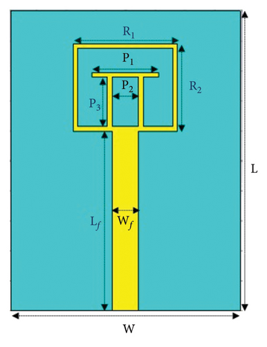
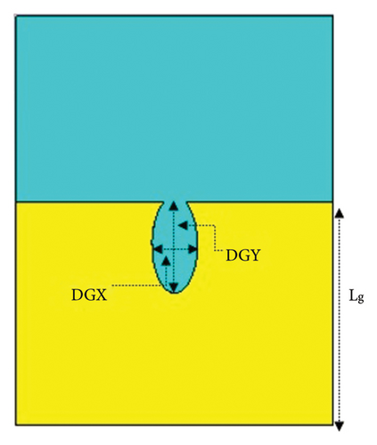
The main aim of adding the surrounding frame is to enhance the performance of the antenna. In addition, its dimensions are optimized for obtaining the required antenna parameters. The radiating unit is fed with a microstrip feedline structure. For achieving the ultra-wideband characteristics, the proposed element antenna includes a half-defected ground plane with an ellipse slot at its top centre. The elliptical slot major and minor axes are tuned to achieve the acceptable input reflection level and broad impedance bandwidth. The element antenna input reflection coefficient performance without an ellipse slot is not at a reasonable level for wideband applications. This work presents a wideband antenna simulated using CST MWS and Ansys HFSS electromagnetic simulators, which work based on finite integration technique (FIT) and finite element method (FEM), respectively. Compared to HFSS, CST MWS needs less time in the simulation process. The simulation of the proposed array antenna takes much time and is more computationally intensive in Ansys HFSS than CST MWS solver. Hence, CST MWS 2019 is used for modeling, simulation, and parametric analysis of the single-element antenna, and further analysis of its linear aggregation. Then, Ansys HFSS 2019 is used to validate results from CST. Figures 1(a) and 1(b) show the dimensions of the proposed element antenna. The dimensions include substrate width (W), substrate length (L), ground plane length (Lg), ellipse slot minor radius on ground plane (DGX), ellipse slot major radius on ground plane (DGY), pi-shaped radiating unit arms (P1, P2, and P3), rectangular shaped frame sides (R1 and R2), and feedline width and length (Wf and Lf). In general, these antenna dimensions are summarized in Table 1.
| Design parameters | Values in mm |
|---|---|
| Ground plane length (Lg) | 5.715 |
| Substrate width (W) | 7.7 |
| Substrate length (L) | 10.3 |
| Pi radiating unit arms (P1, P2, and P3) | 2.35, 1.05, and 1.65 |
| Rectangular frame sides (R1 and R2) | 3.5 and 2.9 |
| Feedline width (Wf) | 0.9 |
| Feedline length (Lf) | 6.3 |
| Ground plane slot (ellipse minor radius) (DGX) | 1.117 |
| Ground plane slot (ellipse major radius) (DGY) | 2.145 |
2.1. Parametric Analysis of Single-Element Antenna
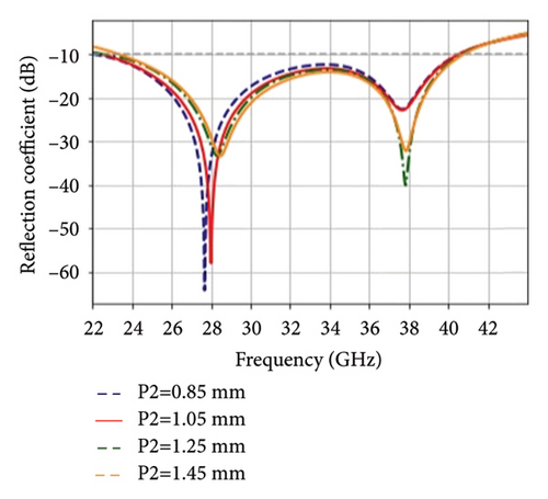
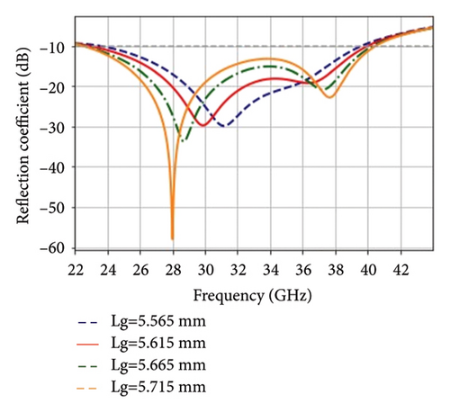
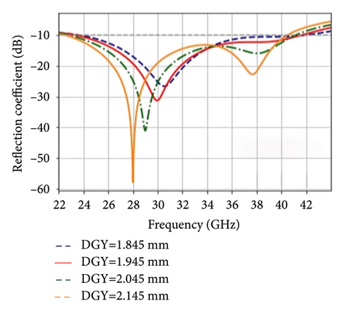
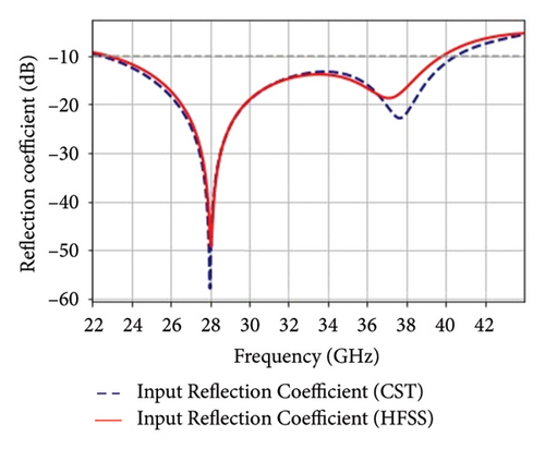
In antenna design, understanding how different geometrical parameters affect performance is crucial for achieving desired specifications such as impedance matching, bandwidth, reflection coefficient, gain, and radiation pattern. The parametric study helps in identifying the optimal set of parameters that meet the design goals. The systematic evolution followed to develop the single-element antenna configuration involves tuning different geometric parameters including pi-radiating unit arms, rectangular frame sides, defected ground length, feedline lengths, and minor and major radius of the ground plane slot. From these, P2, Lg, and DGY are opted for parametric analysis, as their effect was significant on S11 during manual optimization of the single-element antenna before finalizing the design. Figures 2(a), 2(b), and 2(c) show how a change in the physical parameters of the element antenna P2, Lg, and DGY play a vital role in input reflection coefficient performance, respectively. The gap between the two arms of the pi-radiating unit (P2) varied from 0.85 mm to 1.45 mm with an interval of 0.15 mm. As P2 increases, the input reflection-coefficient response increases and its lowest points shift away from the operating frequency of the single-element antenna (28 GHz). The gap (P2) with a value of 1.05 mm gives the optimum input reflection coefficient at the desired frequency. The other parameter considered for manual optimization is ground plane length (Lg). This parameter is varied from 5.565 mm to 5.715 with a step size of 0.05 mm. In the optimization process, as seen in Figure 2(b), Lg = 5.715 mm results in improved input reflection coefficient performance. Figure 2(c) also shows the impact of varying DGY on S11. The increment of the major radius of the ground plane slot improves S11 performance of the element antenna. In addition, as we vary the ellipse notch at the ground, impedance bandwidth is improved. Lastly, the single-element antenna was designed and simulated using the parameters shown in Table 1. Figure 2(d) depicts the comparison of results of the manually optimized antenna using electromagnetic solvers CST MWS 2019 and Ansys HFSS 2019, where the results show a reasonable agreement.
3. LPAA Design and Configurations
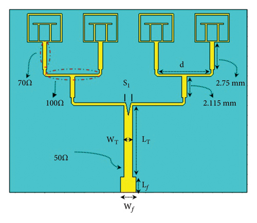
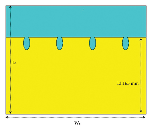
Figure 3 depicts the geometric configuration of the four-element linear planar antenna array with high gain and wideband characteristics. The array consists of identical radiating units separated by a distance d, and the four identical radiating units are fed with a 1 × 4 microstrip line power divider. The initial antenna array designed on ultrathin RT/duroid 5880 substrates has a total dimension of 23.6 × 18.5 × 0.125 mm3 and is simulated using a CST Microwave simulator. Figures 3(a) and 3(b) show the top and bottom sides of the designed antenna array, respectively. In addition, for achieving wide impedance bandwidth, mutual coupling reduction [31, 32], and antenna miniaturization, the proposed array includes a partly defected ground structure (PDGS) with four equally spaced ellipse slots at its top edge. The detailed dimensions of the array are shown in Figures 3(a) and 3(b) which include substrate width and length (Ws and Ls), quarter-wave transformer width and length (WT and LT), feedline width and length (Wf and Lf), and interelement spacing (d). As seen in Figure 3(a), the simple feed structure of a four-element linear array antenna is composed of a 50 Ω transmission line that splits into two parallel lines of 100 Ω and then connected to 70 Ω lines with a power divider technique [33]. The feed structure corners are also slanted to achieve good impedance matching. Table 2 shows the detailed dimensions of a quarter-wave transformer approach [34] feeding structure. To achieve good impedance matching, these dimensions are manually tuned and optimized.
| Design parameters | Values in mm |
|---|---|
| Feedline length (Lf) | 1.55 |
| Feedline width (Wf) | 1.56 |
| Transformer width (WT) | 0.9 |
| Transformer width (LT) | 7.4 |
| 70 Ω line width | 0.42 |
| 100 Ω line width | 0.26 |
3.1. Physical Parameter Variation and Analysis of LPAA
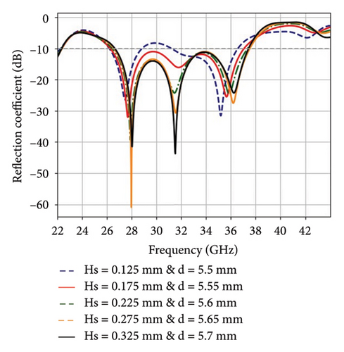
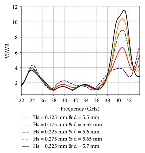
Figure 4(a) shows how a combined change in the substrate height (Hs) and interelement spacing (d) play a vital role in the input reflection-coefficient performance. At intervals of 0.05 mm, the substrate height and element spacing varied from 0.125 mm to 0.425 mm and 5.5 mm to 5.775 mm, respectively. The optimal input reflection coefficient at the desired frequency is achieved with Hs = 0.275 mm and d = 5.65 mm. Figure 4(b) also shows the VSWR curve pattern by varying Hs and d in a similar fashion. An additional slot (S1), incorporated into the antenna array’s feeding structure, is to improve impedance matching and bandwidth of the antenna.
4. Mathematical Modelling and Multiple Response Optimizations of LPAA
The systematic activities we followed to design and optimize the proposed linear planar antenna array with a quarter-wave transformer were adapted from the methods in [28]. Initially, a wideband pi-shaped element antenna framed within a rectangular structure is designed, and then its parametric analysis using CST studio. The results of the single-element antenna simulated using CST studio are validated using HFSS. Then, a wideband four-element linear planar antenna array with a simple four-element feed network is designed and characterized using CST studio. In addition, the linear antenna array initially designed has a dimension of 23.6 × 18.5 × 0.125 mm3. This antenna gives a bandwidth of 7.921 GHz and a gain of 6.62 dBi. To improve the performance of the designed antenna, it requires optimization strategy of physical factors that affect the antenna responses. Several physical factors can influence the responses of the designed linear planar array antenna such as patch width, length, thickness, substrate length, width and thickness, slot dimensions on ground and patch, interelement spacing, and feeding structures’ width and length. From this wide range of physical factors, substrate height [35] and interelement spacing [36] are the two parameters that play an important role in maximizing the radiation characteristics of the proposed antenna.
As variations of substrate height (Hs) and interelement spacing (d) have a significant effect on antenna performance, these two design parameters are considered for dataset preparations that can be utilized for analytical modeling. Table 3 shows the dataset prepared by varying these parameters and repeatedly simulating linear planar array antenna. As seen from Table 3, substrate height (Hs) is varied from 0.125 mm to 0.425 mm, as the aim is to design an ultrathin array antenna. Similarly, interelement spacing is varied from 5.5 mm to 5.775 mm, which is near to λ0/2 [37] where λ0 is the free space wavelength at the operation frequency. In the process of dataset preparation, 17 linear planar array antenna designs are simulated and analyzed using the CST MWS 2019 solver. As seen from the dataset, increasing substrate height (Hs) improves the impedance bandwidth of the proposed antenna array.
| Hs (mm) | Ws (mm) | d (mm) | Fr (GHz) | S11 (dB) | BW (GHz) |
|---|---|---|---|---|---|
| 0.425 | 24.425 | 5.775 | 28.11 | −30.38 | 9.282 |
| 0.4 | 24.425 | 5.775 | 28.138 | −31.227 | 10.323 |
| 0.4 | 24.35 | 5.75 | 28.248 | −32.322 | 10.366 |
| 0.375 | 24.35 | 5.75 | 28.116 | −35.354 | 10.511 |
| 0.35 | 24.35 | 5.75 | 28.028 | −36.106 | 10.607 |
| 0.35 | 24.35 | 5.725 | 28.094 | −36.898 | 10.625 |
| 0.325 | 24.2 | 5.7 | 28.028 | −42.168 | 10.761 |
| 0.3 | 24.2 | 5.7 | 27.918 | −46.528 | 10.846 |
| 0.3 | 24.05 | 5.65 | 28.094 | −48.801 | 10.838 |
| 0.275 | 24.05 | 5.65 | 27.984 | −60.954 | 10.943 |
| 0.25 | 24.05 | 5.65 | 27.852 | −40.964 | 11.002 |
| 0.25 | 23.9 | 5.6 | 28.028 | −36.163 | 11.046 |
| 0.225 | 23.9 | 5.6 | 27.918 | −39.437 | 10.881 |
| 0.2 | 23.9 | 5.6 | 27.764 | −33.745 | 10.893 |
| 0.2 | 23.75 | 5.55 | 27.837 | −35.986 | 10.86 |
| 0.175 | 23.75 | 5.55 | 27.698 | −32.043 | 10.768 |
| 0.125 | 23.6 | 5.5 | 27.476 | −26.329 | 7.921 |
Once the dataset is prepared, the next step is employing an optimization strategy to achieve the desired radiation characteristics. The conventional optimization procedure involves time-intensive repeated simulations using an electromagnetic simulator. Whereas, in this work RSM, we used a robust method for the design of experiments (DoE), experimental data analysis, and time-efficient optimization technique. The first activity as part of DoE is to define independent and dependent variables [38]. The substrate height and interelement spacing are independent variables, while operating frequency, bandwidth, and input reflection coefficient are the three dependent variables or responses considered for the optimization of the proposed antenna. These antenna parameters are representative for achieving the maximum possible bandwidth and lowest possible input reflection coefficient at the target operating frequency, 28 GHz, which has a high demand for 5G wireless communication applications. The linear aggregation of single-element antennas maximizes the other important parameter of the proposed antenna, which is gain. The approach followed in this work considers gain-bandwidth trade-off and simultaneously enhances both antenna parameters. The defected ground plane enhances bandwidth in the cost of gain and is tuned to optimize between the two parameters.
Next to statistically designing the experiments and estimating the coefficients of mathematical models, predicting the response and checking the fitness of the models are important optimization steps in RSM. Analysis of variance (ANOVA) and residual analysis are the most common techniques employed to assess the model’s fitness and whenever necessary, the model treatment is performed to improve convergence speed and accuracy [28, 29]. One of the ANOVA parameters that shows the model’s accuracy in predicting future outputs is coefficients of determination (R2). The model fits the data well if the R2 value is close to unity. The coefficients of determination values for Fr and BW models are 0.9778 and 0.8328, respectively, which show that the proposed models can accurately predict future responses. The other ANOVA parameter that decides which terms to include as part of the model is p where parameters with p < 0.05 are considered as significant terms. Hence, both ANOVA parameters are checked from the ANOVA table generated during the model fitness assessment. As seen from equations (2) and (3), the responses are influenced by substrate height (Hs) and interelement spacing (d) single factor terms, the interaction between substrate height and interelement spacing (Hsd), and their squares and their interactions ( and Hsd2). Furthermore, models are validated by applying residual analysis where it represents the difference between the actual values and the predicted values. As part of the model fitness assessment, we checked the residual plots. The points in the plot are along a straight line, which show that the proposed models are good. Similarly, the other plots considered in the model assessment are the response surface and contour plots due to the interaction between variables. The response surface plots are reasonably flat curvatures that show the effectiveness of the models [29].
Once well-fitted models are developed, a constrained numerical optimization technique is applied to determine the optimized four-element linear planar antenna array’s physical parameters. The optimization goals of responses in the Design-Expert software are set as minimize, maximize, or target value. The constraint optimization summary is shown in Table 4. The optimization goal for response Fr is set as a target of value 28 GHz, whereas BW is set as maximize with an upper limit of 11.25 GHz. The lower and upper weights are also set as one. Following constrained optimization, a list of factor solutions with unity desirability is generated, with the highest-ranked candidate being designated as the selected option from all feasible solutions. Among the list of optimal solutions, the LPAA parameters with desirability of one and selected status are as follows: substrate height = 0.263 mm and interelement spacing = 5.63 mm. Subsequently, the performance of the optimized antenna is validated through simulation using electromagnetic solvers CST MWS 2019 and Ansys HFSS 2019.
| Design parameters | Goal | Lower limit (mm) | Upper limit (mm) |
|---|---|---|---|
| Substrate height (Hs) | Is in range | 0.125 | 0.45 |
| Interelement spacing (d) | Is in range | 5 | 6 |
| Resonating frequency (Fr) | Is target = 28 | 27 | 28.8 |
| Bandwidth (BW) | Maximize = 11 | 7.921 | 11.25 |
5. Optimized Antenna Results and Discussions
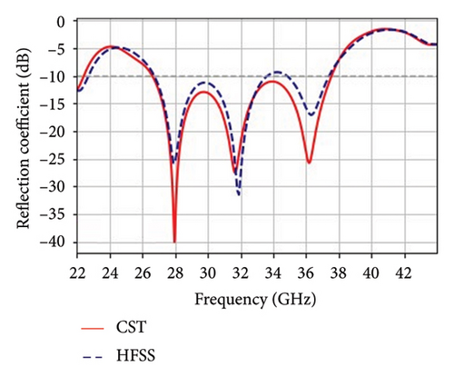
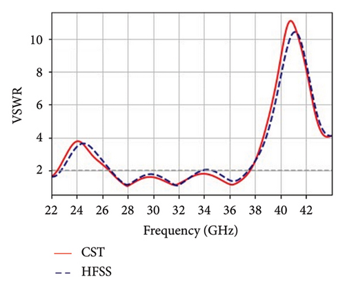
The main objectives of this work are to design a wideband LPAA and optimize the designed antenna based on the combined effect of parameter variation on impedance bandwidth and resonating frequency. In the previous section, the effect of substrate height and interelement spacing on the antenna performances is observed. In this section, the sample results of the optimized antenna are discussed where the antenna is designed using the geometrical dimensions in Table 5. Figure 5(a) shows the input reflection-coefficient variation concerning the optimized antenna’s frequency. Operating between 26.5 GHz and 37.6 GHz, the simulated result gives an impedance bandwidth of 11.1 GHz, which is close to the optimization goal (11.25 GHz). As seen from the plot, simulation results using CST MWS EM solver and Ansys HFSS 2019 are compared. The input reflection coefficient and impedance bandwidth results obtained by both solvers are in good agreement. In the antenna’s operating frequency range, there is only a reasonable difference in the level of the input reflection coefficient. Figure 5(b) also shows the plot of VSWR, the other antenna parameter that measures how well an antenna matches at the feed point. Ideally, the magnitude of VSWR is 1, but its value could lie below 2 or 3 [39]. As can be seen, the simulated VSWR for the optimized LPAA design using the two EM simulators is less than 2 throughout its operating frequency range. The VSWR also shows good agreement in both EM solvers with slight differences. These tolerable differences arise as the two solvers use different approaches for the substrate losses at high frequencies, and meshing techniques [40, 41]. The method used by HFSS to compute Maxwell’s equations in the frequency domain is FEM. On the other hand, CST computes this by using the FIT method [42]. Furthermore, the S11 and VSWR results demonstrate the model’s effectiveness in optimizing the antenna’s geometrical parameters.
| Design parameters | Dimensions (mm) |
|---|---|
| Substrate width (Ws) | 23.99 |
| Substrate length (Ls) | 18.55 |
| Interelement spacing (d) | 5.61 |
| Quarter-wave transformer width WT | 0.9 |
| Quarter-wave transformer width (LT) | 7.254 |
| Feedline length (Lf) | 1.55 |
| Feedline width (Wf) | 1.56 |
| Substrate height (Hs) | 0.263 |
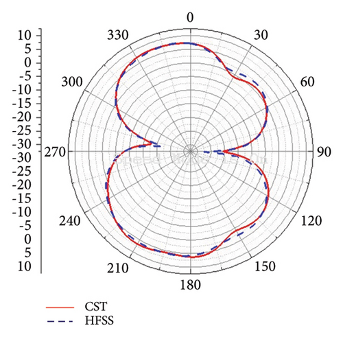
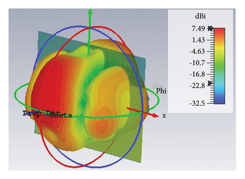
The 2D and 3D graphical radiation characteristics of the proposed LPAA are depicted in Figures 6 and 7, respectively. The radiation pattern generally describes how the antenna radiates and receives energy into and from space. Figures 6(a) and 6(b) compare the 2D radiation patterns of the antenna as simulated at 28 GHz using CST and HFSS EM simulators. The simulated radiation patterns show a reasonable agreement. These 2D radiation patterns are simulated at Phi = 90° and Phi = 0°. The antenna provides a 7.49 dBi peak directivity at 28 GHz, where the directivity of the antenna refers to the ratio of the radiation intensity in a given direction to the radiation intensity averaged over all directions. As seen from Figure 6(a), the main lobe radiation direction corresponds to an angle of Theta = 21° and a null at Theta = 90°. Furthermore, Figure 7 shows the 3D far-field radiation pattern of the proposed antenna at 28 GHz. The 3D plot demonstrates a dual-beam characteristic with a very narrow beamwidth that signifies that the proposed array meets the requirements for mm-wave systems [19].

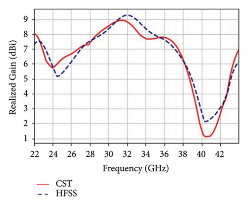
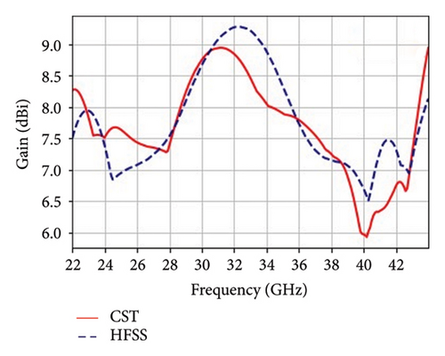
The other antenna parameter simulated to measure the antenna performance is the gain which measures the effectiveness of an antenna in directing the radiated power in the desired direction. Figure 8(a) shows the realized gain versus frequency curves of the proposed antenna as simulated by CST and HFSS. In the operating band of the proposed antenna, a maximum of 9.25 dBi gain is achieved at 32.2 GHz using HFSS and 9.02 dBi at 31.2 GHz using CST. The gain is relatively lesser in the lower and higher frequency ranges, whereas it gives maximum gain in the middle frequency range. Figure 8(b) also shows the gain comparison of the optimized antenna over the range of operating frequencies as simulated by CST and HFSS EM solver. As can be seen from the plots, both gain profiles in the CST and HFSS show a good agreement.
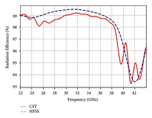
Radiation efficiency is another parameter that measures how effectively an antenna transmits and receives RF signals where its value is the ratio of the total power radiated to the total input power received by the antenna. Figure 9 compares the radiation efficiency of the proposed antenna array. In the operating frequency range of the antenna, −0.036 dB (99.177%) and −0.0225 dB (99.48%) are the maximum efficiencies achieved by using CST and HFSS, respectively. The antenna provides high radiation efficiency, indicating that it effectively radiates the input power into free space. The radiation efficiencies achieved using CST and HFSS simulators are within a reasonable agreement.
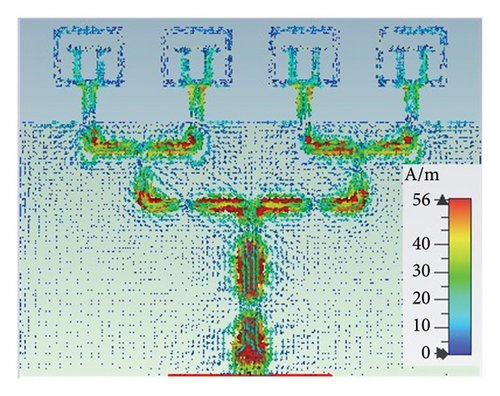
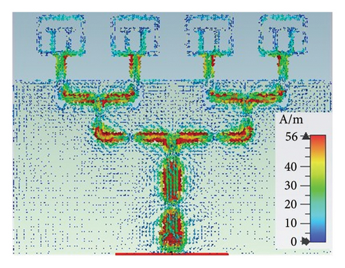
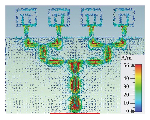
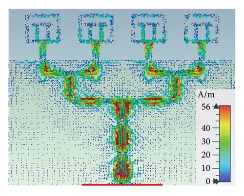
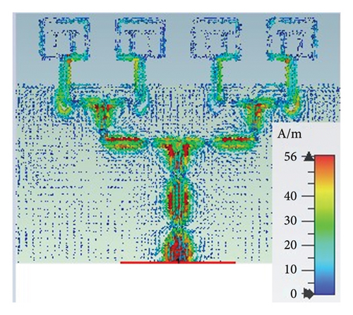
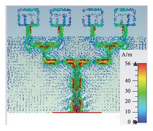
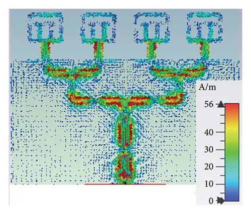
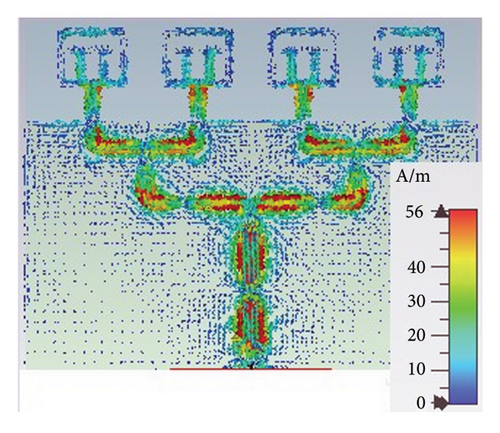
Furthermore, the performance of the optimized antenna is evaluated by analyzing the surface current distribution, as simulated in CST, at selected frequencies within the antenna’s operating band. As shown in Figures 10(a) and 10(d), at a frequency of 27 GHz and 36 GHz, the maximum current intensity is mainly focused on the entire feeding structure of the antenna and with relatively lower current intensity on the inner and outer frames of the patch. Figures 10(b) and 10(c) also show that at 28 GHz and 32 GHz, the surface current is distributed at the edges of the four radiating elements and around the feedline. As can be seen from the plots, surface current intensity is higher in the middle range of resonant frequencies than in upper and lower band resonant frequencies, which validates the gain variation of the proposed antenna [43]. The surface current of the proposed antenna array is also simulated by varying the phase angle of the power sources. Figures 11(a), 11(b), 11(c), and 11(d) show that as the phase angle increases, the current intensity also increases around the four patches. The phase angle varied from 30° to 120° with a gap of 30°. During simulation, a maximum of 199 A/m current intensity is observed and intentionally decreased to 56 A/m for better observability.
In general, the proposed antenna results obtained from the two EM solvers are summarized in Table 6. As can be seen from the table, the results of the two softwares show a reasonable agreement.
| EM solver | Operating frequency (GHz) | Gain (dBi) | Bandwidth (GHz) | S11 (dB) | VSWR | Radiation efficiency (%) |
|---|---|---|---|---|---|---|
| CST | 28 | 7.49 | 11 | −40.065 | 1.02 | 98.6 |
| HFSS | 28 | 7.5 | 9.4 | −25.75 | 1.109 | 99.3 |
To validate the proposed model equations and optimized array antenna, results generated using CST EM simulator are compared with recent published works. Table 7 summarizes the proposed antenna contributions in comparison with references in terms of overall size, antenna elements, configuration, bandwidth, gain, and efficiency. In [20], a 1 × 4 linear array with a dimension of 20 mm × 22 was designed on RT/duroid 5880 substrates with 0.256 mm thickness for 5G applications. The reported antenna provides a gain of approximately 10.7 dBi but with a bandwidth of 4 GHz. The other related work in [21] reported a four-element linear array antenna with a size of 18.5 mm × 24 mm and achieved a high-realized gain of 11.5 dBi and 94% efficiency, but a bandwidth of 4 GHz. The proposed antenna is compared with recent advancements and published works that follow different antenna array configurations such as planar [20, 21, 44, 45], multiple-input–multiple-output (MIM) [46–50], and SIW [51]. The antennas in [44, 45] with four-element antenna achieved high gain but narrow bandwidth and relatively less radiation efficiency. The other related works in [46–50] with MIM configurations provide comparatively less gain and narrow bandwidth. Though the gain and bandwidth achieved in [51] with SIW configuration is high, the cavity of the antenna makes it difficult to integrate into miniature printed boards. Again, the total dimension of this antenna is large and gives less radiation efficiency. As seen in Table 7, the proposed antenna array provides a wide impedance bandwidth close to the optimization target (11.25 GHz). It also gives a high gain with a radiation efficiency of ≥98.5% in the operating band of the antenna. In addition to parametric analysis, our work proposed an optimized LPAA along with mathematical models for predicting the antenna responses for different values of substrate height and interelement spacing. The input reflection coefficient and VSWR performances signify that the antenna is in a good matching compared to other published results. In addition, the optimized antenna is a simple planar antenna with a simple feeding structure and compact size. As seen from Table 7, the proposed antenna array provides high gain and wide bandwidth characteristics with reduced size as compared to related works. The wide bandwidth characteristics of the optimized LPAA are crucial for smooth operation and addressing future bandwidth demand of mmWave wireless communication system. Furthermore, its high gain can help to overcome atmospheric attenuation in the mmWave range. Hence, its performance makes it a good candidate for applications, which require high gain and wide bandwidth such as high speed and low latency mmWave wireless communications.
| References | Antenna elements | Configuration | Size (mm2) | Gain (dBi) | Bandwidth (GHz) | Radiation efficiency (%) |
|---|---|---|---|---|---|---|
| [18] | 1 × 4 | Planar | 20 × 22 | 10.7 | 4 | 90 |
| [19] | 1 × 4 | Planar | 18.5 × 24 | 11.5 | 4 | 94 |
| [44] | 1 × 4 | Planar | 32 × 12 | 10.12 | 1.41 | ≥80 |
| [45] | 2 × 2 | Planar | 35 × 37 | 9.49 | 5.82 | NA |
| [46] | 4 | MIM | 30 × 30 | 6.1 | 1.9 | 92 |
| [47] | 4 | MIM | 25 × 15 | 7.8 | 2 | 95 |
| [48] | 4 | MIM | 20 × 24 | 7.9 | 2.2 | >85 |
| [49] | 4 | MIM | 30 × 30 | 7.1 | 4 | >90 |
| [50] | 4 | MIM | 22 × 22 | 6.2 | 3.8 | ≤89 |
| [51] | 1 × 4 | SIW | 20 × 45 | 12.1 | 9.871 | >85 |
| This work | 1 × 4 | Planar | 18.55 × 23.99 | 9.02 | 11 | ≥98.6 |
- NA: not applicable.
6. Conclusions
In this work, a novel pi-shaped antenna element framed within a rectangular structure is designed on a thin RO5880 substrate. The designed antenna element provides a wideband ranging from 22.482 GHz to 40.511 GHz, with a gain of 3 dBi and radiation efficiency of 90% at 28 GHz. To enhance the performance of the antenna element, parametric analysis is conducted by varying geometric parameters of the single antenna structure. Then, this single antenna element is transformed into a 1 × 4 linear array. The proposed four-element antenna array results from EM simulations are recorded as a dataset by varying geometric parameters of the antenna structure. Then, mathematical models which relate responses (resonating frequency and bandwidth) and factors (substrate height and interelement spacing) are developed applying response surface methodology. The desired responses are predicted using a constrained numerical optimization. The size of the optimized antenna is 0.263 mm × 18.55 mm × 23.99 mm, where interelement spacing d = 5.61 mm. Once, the optimized geometric parameters are predicted, the antenna results are validated by comparing the results of CST and HFSS EM solvers. The peak gain achieved is 9.02 dBi and at 28 GHz a gain of 7.5 dBi is achieved. In addition, the impedance bandwidth performance of the optimized LPAA is 11 GHz using CST and 9.4 GHz using HFSS simulators. The radiation efficiency and VSWR performances in the operating band of the optimized antenna are ≥98.5% and less than 2, respectively. The simulation results are validated using two EM simulators and show a reasonable agreement. Thus, mathematical modeling and optimization techniques employed in this work using Design Expert constitute a competent approach for enhancing the performance of high-frequency antenna arrays. As compared with related works, the proposed antenna provides good performance that makes it suitable for high-speed mmWave communication applications.
Conflicts of Interest
The authors declare that there are no conflicts of interest regarding the publication of this article.
Open Research
Data Availability
All necessary data are included as part of the article. If more is needed, it will be available upon request to the authors.


