Analysis of Vibration Characteristics of Hydraulic Excavator Device Under Flat Ground Conditions
Abstract
Hydraulic excavators, characterized by their high efficiency and versatility, are crucial equipment in engineering construction. During the automatic excavation process, the excavator may experience resonance phenomena, which can affect the stability of the entire system. In order to study the vibration harmonic response of the excavator arm in the process of reciprocating motion, firstly, the model of the excavator arm is designed in three-dimensional software, and the finite element meshing software is used to perform hexahedral meshing of the excavator arm model and define the material properties. Secondly, the modal analysis of the excavator arm is carried out by finite element simulation software, and the displacement and acceleration harmonic response analysis is carried out using the modal superposition method. Finally, the vibration experiment of reciprocating motion with different frequencies is carried out on the experimental platform of the excavator arm. The simulation and experimental results show that the maximum value of the displacement and acceleration response of the excavator arm corresponds to the frequency near the second-order intrinsic frequency, and the excavator arm is greatly affected by the second-order intrinsic frequency; controlling the frequency of the reciprocating motion of the hydraulic cylinder within 13 Hz can effectively avoid the resonance phenomenon of the excavator arm device.
1. Introduction
As a kind of mechanical equipment with high efficiency and energy saving, precise operation, strong adaptability, and convenient maintenance, a hydraulic excavator is widely used in industrial and civil infrastructure construction, water conservancy, transportation engineering, mining extraction, and other fields [1–3]. The traditional manual operation mode in excavator operation has the problems of low efficiency, uneven construction quality, and significant safety hazards, which not only affect the project progress but also may cause potential threats to the quality of the project, and even threaten the life safety of the operator [4]. Therefore, an in-depth study of excavator automatic trajectory control technology not only has important theoretical value but also has a wide range of application prospects.
Excavator trajectory planning is the use of algorithms to determine the optimal trajectory of an excavator during operation to achieve efficient, safe, and reliable excavation operations. Literature [5–7] uses optimization algorithms to optimize the trajectory of the excavator to achieve the trajectory planning of the hydraulic excavator with less time, high efficiency, and optimal energy consumption, which significantly improves the efficiency and effectiveness of the continuous excavation task. The excavator in the automatic trajectory control process to control the hydraulic cylinder expansion and contraction will produce a certain amount of vibration when the frequency of the hydraulic cylinder expansion and contraction and the excavator working device of the inherent frequency of the same will produce a resonance phenomenon, so in order to optimize the structure and control of the vibration characteristics of the excavator arm working device, it needs to be analyzed.
Dynamics research can effectively alleviate the vibration problem and improve the precision and life of mechanical manufacturing equipment, and scholars at home and abroad have achieved many results in the vibration analysis of mechanical equipment as well as other structures. Literature [8] uses piezoelectric microvibration testing and frequency analysis methods to test materials, compare their damping characteristics, and determine the attenuation and intrinsic frequency of the object. In literature [9], in order to avoid the vibration that may lead to arm fatigue damage, the establishment of the human arm finite element model, through the modal analysis of the robotic arm and dynamics simulation, found that the robotic arm vibration in the range of 5~10 Hz and 35~40 Hz may lead to arm fatigue damage and should be avoided in these frequency ranges of the vibration of the handle in direct contact with the handle. Literature [10] for a certain type of five-axis CNC machine tool column deformation serious problems, the establishment of a certain type of five-axis CNC machine tool finite element model, through the modal and harmonic response analysis reveals the first six intrinsic frequencies and vibration modes, for the optimization of the structure of the column, provides a theoretical basis. In literature [11], in order to study the vibration harmonic response of the robotic arm under load, modal analysis through ANSYS is used to obtain the self-oscillation frequency and response effect of the key components and to provide an important reference for the structural design and improvement of the robotic arm. Literature [12] uses the ANSYS Workbench for vibration analysis of load port independent control system active and passive loading test rigs. The frequency of the loading force is controlled within 35 Hz, which can effectively avoid the resonance phenomenon. In order to suppress the resonance phenomenon of large headframe, literature [13] proposed a method of dynamic characteristic analysis and structural optimization design for large headframe and revealed its intrinsic frequency and vibration mode characteristics through modal analysis. The results show that the method provides a new idea for the structural optimization design of large mining derricks and helps to suppress resonance. Literature [14] carried out finite element modal analysis and harmonic response analysis on the boom of a truck crane. The results of modal analysis to understand the impact of different frequency loads on the moving arm provide a theoretical basis for the optimization of the structural design of the moving arm. Literature [15] conducted modal harmonic response analysis in order to ensure the safety of the equipment cabinet structure under sudden impact loads. And the strengthening of the equipment cabinet structure was carried out according to the stress and deformation of the components under vibration and impact loads. In literature [16], in order to avoid cracks or even fractures of hydraulic pipelines due to vibration problems during system operation, modal analysis and harmonic response analysis of pipelines are carried out to provide theoretical guidance for pipeline vibration research. Literature [17] for aviation thin-walled spiral bevel gear prone to traveling wave vibration problems puts forward a curved bevel gear contact finite element model based on an efficient traveling wave vibration analysis method. The comparison results of modal analysis and harmonic response analysis show that the increase in the thickness of the gear blank web reduces the peak stress, and the increase in the thickness of the bevel web and the angle of the bevel web reduces the peak stress of the compound vibration. Literature [18] found that the working position of the spindle box has a significant impact on the dynamic characteristics of the machine tool by analyzing the dynamics of different positions of a large CNC machining machine, which provides a guide to selecting a suitable machining position during the cutting process. Finite element vibration analysis not only provides theoretical guidance for mechanical structure optimization and avoiding system resonance phenomena but also provides a powerful analytical tool for accurate prediction of product dynamic performance and reliability assessment. Literature [19] improved the vibration harvesting efficiency of jujube by vibration analysis of jujube trees with different diameters and determined the optimal parameters for harvesting under different jujube tree diameters. Literature [20] designed a trunk-type vibration picker with a frequency of 12.7 Hz specifically for crab apple harvesting by performing modal analysis and harmonic response analysis on a green crab apple tree. In addition, vibration analysis is widely used in fault diagnosis and prediction and reliability assessment [21, 22].
Therefore, this paper takes the 2 T excavator arm device as the research object to analyze the vibration characteristics. Three-dimensional software is used to design the three-dimensional model of the excavator arm, and the model is imported into the finite element meshing software for meshing. Based on the finite element simulation software, finite element modal and harmonic response analyses were carried out for the excavator arm in flat linear condition, and the 1st–6th-order natural frequencies and vibration patterns of the excavator arm were obtained. According to the simulation analysis, the excavator arm reciprocating motion vibration experiment was carried out. By comparing and analyzing the natural frequency, displacement response, acceleration response, and acceleration transfer path of the excavator arm device, a theoretical reference is provided for the avoidance of resonance in the reciprocating motion control process of the hydraulic cylinder of the excavator arm.
The rest of the paper is structured as follows. The excavator arm finite element model is presented in Section 2. Modal analysis is presented in Section 3. In Section 4, harmonic response simulation analysis as well as an experimental study are carried out. In Section 5, a summary is presented.
2. Excavator Arm Finite Element Model
2.1. 3D Modeling
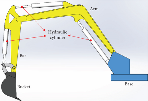
To simulate and analyze the modal and harmonic responses of the hydraulic excavator arm using the ANSYS Workbench, it is first necessary to establish a three-dimensional model of the hydraulic excavator arm. In order to simplify the cumbersome process of three-dimensional modeling, this paper adopts SOLIDWORKS software to establish a three-dimensional model of the hydraulic excavator arm, as shown in Figure 1. The hydraulic excavator arm is a hydraulic and mechanically integrated system, and its core components include the hydraulic bar of the arm, the hydraulic cylinder of the bucket bar, the hydraulic cylinder of the bucket, the arm, the bucket bar, and the bucket, as well as the base that supports these hydraulic actuators. The reasonable establishment of the three-dimensional model of the hydraulic excavator arm is the key to modal and harmonic response analysis. If the local structure is very complex, it will cause an increase in the number of cells required for meshing, and it is also prone to producing distorted mesh cells, which will lead to a reduction in the accuracy of the operation or even the termination of the operation process. Therefore, in order to improve the calculation efficiency, the model is simplified appropriately. Specific simplification operations are as follows: ignore the holes, bolts, chamfers, and other microstructures that have a small impact on the dynamic characteristics of the excavator arm; integrate the tiny planes that have a small impact on the dynamic characteristics of the excavator arm; carry out the equal-mass transformation of the pressure sensors, displacement sensors, and other structures through the assumption of the structure and the equivalent processing; and use the cylindrical surfaces and holes to simulate the joint vice.
2.2. Material Property Setting and Meshing
The 3D model is imported into ANSYS software to generate a finite element model. The material of the excavator arm components is structural steel, and the material parameters are set in the finite element model. After referring to relevant data, the performance parameters of structural steel are shown in Table 1.
| Parameter | Value | Unit |
|---|---|---|
| Density | 7.85 | g·cm−3 |
| Modulus of elasticity | 210 | GPa |
| Poisson’s ratio | 0.3 | — |
| Yield strength | 235 | MPa |
Based on the actual working conditions of the excavator arm moving in a straight line on flat ground, the connection relationships and fixed constraint conditions are set in the modal analysis. Since the excavator arm actually secures the base to the ground, setting the excavator arm base as a fixed support in the model limits the base to six degrees of freedom. Gravity acting downward on the model is applied according to the weight of the excavator arm itself. Joints are added to the finite element model of the excavator arm to simulate the articulated joints.
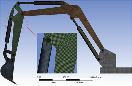
Finally, the finite element model of the excavator arm is meshed. To ensure both computational accuracy and efficiency and to improve the precision of the simulation results for the vibration analysis of the excavator arm, the hexahedral structural mesh is applied to the excavator arm using the meshing software Hypermesh. The unit mesh is set to 5 mm, resulting in a total of 728,728 nodes and 585,032 mesh elements. The average element quality is 0.93072, the average aspect ratio is 1.3248, and the average skewness is 0.14169. The overall mesh of the excavator arm is shown in Figure 2.
3. Modal Analysis
The condition for a nonzero solution in Equation (4) is that the determinant is equal to zero, from which we can obtain the i-th characteristic frequency and the eigenvector of the i-th mode shape. Typically, only the first few characteristic frequencies and vibration modes have a significant impact on the overall structural vibration. Therefore, a simulation analysis is performed on the first six modes of the excavator arm to obtain the first six natural frequencies and mode shapes. The modal analysis results of the excavator arm are shown in Figure 3.


Figure 3 shows the first six vibration modes of the excavator arm structure. Blue represents the minimum amplitude, and red represents the maximum amplitude. The shaded part displays the main vibration modes of the entire mechanism. Based on the modal results in Figure 3, the excavator arm has the following inherent characteristics: the first-order modal natural frequency is 7.4231 Hz, and the modal shape is characterized by the left–right swinging of the bucket, hydraulic cylinder, stick, and boom. The maximum vibration deformation occurs at the bucket position, with a deformation displacement of 4.4533 mm. The second-order modal natural frequency is 15.534 Hz, and the modal shape is characterized by the up–down swinging of the bucket, hydraulic cylinder, stick, and boom. The maximum vibration deformation occurs at the bucket position, with a deformation displacement of 3.6447 mm. The third-order modal natural frequency is 22.518 Hz, and the modal shape is characterized by the left–right torsion of the stick and boom. The maximum vibration deformation occurs at the stick position, with a deformation displacement of 5.2701 mm. The fourth-order modal natural frequency is 30.793 Hz, and the modal shape is characterized by the up–down swinging of the bucket, hydraulic cylinder, stick, and boom. The maximum vibration deformation occurs at the bucket position, with a deformation displacement of 4.964 mm. The fifth-order modal natural frequency is 70.34 Hz, and the modal shape is characterized by the left–right torsion of the stick and boom. The maximum vibration deformation occurs at the bucket position, with a deformation displacement of 7.6685 mm. The sixth-order modal natural frequency is 96.313 Hz, and the modal shape is characterized by the forward–backward torsion of the stick and boom. The maximum vibration deformation occurs at the bucket position, with a deformation displacement of 5.3047 mm. The natural frequencies of the first six orders differ significantly, mainly influenced by the overall mass and stiffness of the excavator arm structure. Since the bottom of the excavator arm model is set with fixed constraints, the minimum amplitude of the modal shape is located at the bottom of the excavator arm, with an amplitude of 0.
The excavator arm discussed in this article will be applied to a small excavator in the future. The engine of a small excavator generally runs at less than 3000 r/min, and the reciprocating motion of the hydraulic cylinder is low-frequency. Therefore, the overall working frequency of the excavator arm is below 30 Hz. According to the results of the modal analysis, the first four natural frequencies are below 30 Hz. When the excavator arm is subjected to alternating loads (system vibration and external load forces) with the same frequency as the natural frequency under complex working conditions, it is prone to intense vibration responses, that is, resonance. To investigate the vibration response characteristics of the excavator arm under alternating loads, a harmonic response analysis will be conducted on the excavator arm.
4. Harmonic Response Analysis
4.1. Simulation Analysis
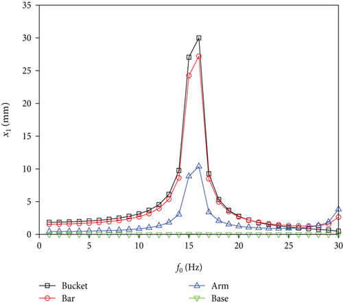
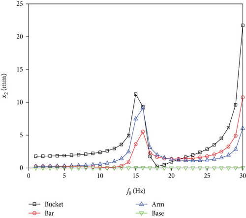
According to the actual situation of the excavator arm in the data calculation, a tangential cutting resistance of up to 2502 N and a normal phase cutting resistance of up to 504 N can be derived. This resistance is a sinusoidal excitation signal with a fixed initial force. The frequency of the excitation signal is set between 0 and 30 Hz, and the interval frequency is set to 1 Hz. According to the harmonic response analysis of the displacement change, four nodes of the excavator arm structure are selected: the bucket, the bucket pole, the big arm, and the upper surface of the base, and the change of the Y-direction displacement x1 and Z-direction displacement x2 response change with the change of the scanning frequency is obtained, as shown in Figure 4. From Figure 4, it can be clearly seen that the Y-direction displacement response is generally larger than the Z-direction displacement response near the second-order intrinsic frequency, at which the excavator arm device mainly vibrates up and down. In the Y-direction displacement response, all nodes reach their maximum values when the scanning frequency is near 16 Hz, and the excavator arm structure vibrates significantly in the vicinity of this frequency. By comparing the intrinsic frequency, the maximum displacement response frequency in the Y-upward direction is close to the vicinity of the second-order intrinsic frequency (15.534 Hz), and the results of the modal and harmonic response analysis are more accurate, so that its own vibration is greatly affected by the intrinsic frequency; resonance is easily induced when its own frequency is the same as the intrinsic frequency. Therefore, when the excavator arm is working, the frequency is avoided at 16 Hz as much as possible to avoid the resonance phenomenon of the excavator arm.
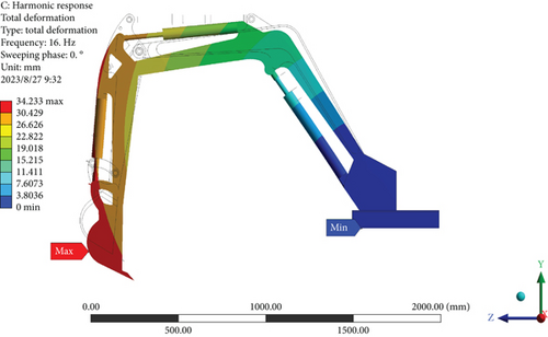
The maximum amplitude of the overall vibration mode of the excavator arm structure is located in the bucket part, and the vibration model of the excavator arm structure at a frequency of 16 Hz is shown in Figure 5. From the displacement response in Figure 5, it can be seen that the displacement response of the excavator arm at the shovel teeth is the largest, and the maximum deformation displacement is 34.233 mm; in addition, the displacement and deformation from the bucket to the base decrease gradually, and the displacement response of the base of the stationary work unit is zero.
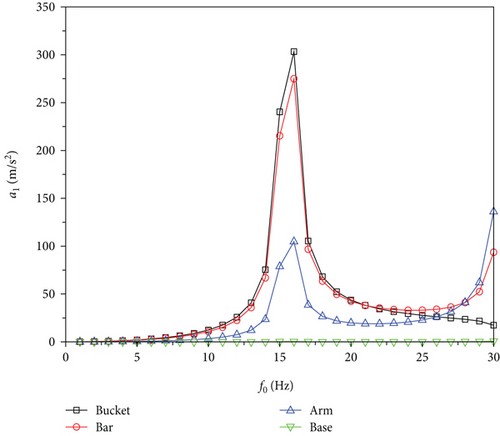
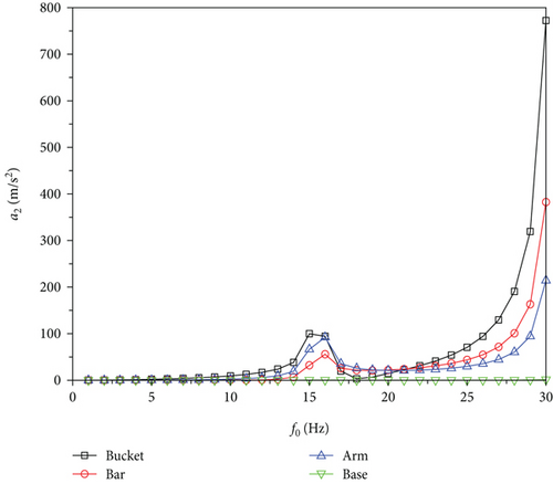
In order to study the vibration state of the excavator arm device after an excitation signal is applied, the acceleration of the excavator arm device is analyzed. Using the excitation signal in the above displacement response analysis to analyze the acceleration response of the device, according to the acceleration response analysis, it can be seen that the acceleration response is also greatly affected by the intrinsic frequency. The use of the acceleration change response to the vibration path generated by the excavator arm device digging resistance to the vibration path is analyzed, respectively. The working device was selected to carry out a simulation analysis of the vibration node on the bucket, the bucket rod, the arm, and the base to derive the acceleration response curve, as shown in Figure 6. From the acceleration response of the four nodes in Figure 6, it can be seen that in the Y- and Z-direction acceleration response, the bucket on the excavator arm device has the largest acceleration load, and it can be deduced that the main path of transverse vibration transmission is from the bucket to the bucket rod to be met by the arm and finally to the base. The acceleration of the excavator arm structure reaches its maximum when the frequency is 16 Hz.
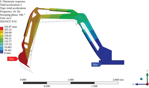
The overall acceleration response of the excavator arm mechanism at 16 Hz is shown in Figure 7. From Figure 7 acceleration response, it can be seen that the acceleration response and displacement response are basically the same distribution on the excavator arm device; the acceleration response of the bucket is the largest and the acceleration response of the base is the smallest, and the simulation illustrates that the deformation of the whole machine is the same under the two types of analysis.
4.2. Experimental of Vibration Harmonic Response
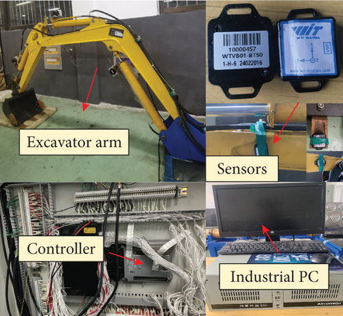
Harmonic response analysis experiments are used to determine the steady-state response of the excavator arm structure when subjected to loads varying with the simple harmonic law. In order to verify the accuracy of the excavator arm harmonic response simulation analysis and, at the same time, to avoid the phenomenon of resonance in the process of the movement of the excavator arm, the experimental validation of the excavator arm device is carried out, and the experimental platform is shown in Figure 8. The experimental platform includes the control system and test system of the excavator arm, and the control system is mainly composed of the host computer, controller, etc., which is mainly used to control the simple harmonic motion of the excavator arm, and the motion frequency is between 0 and 30 Hz. The test system mainly uses the model WTVB01-BT50 industrial Bluetooth 5.0 wireless vibration sensor to test the displacement, inclination, and acceleration of the excavator arm under simple harmonic motion.
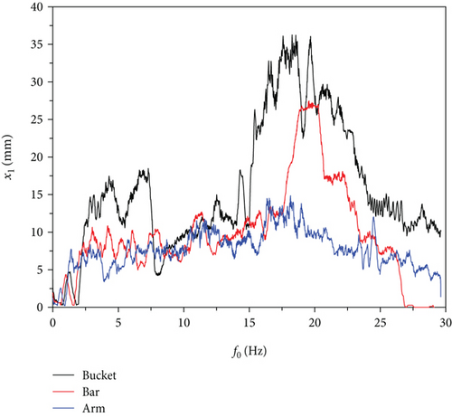
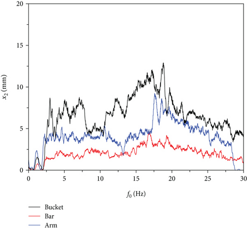
In the excavator, the simple harmonic motion process of the displacement changes in the excavator arm selected three nodes: bucket, bucket rod, and moving arm surface, to get the Y-direction displacement x1 and Z-direction displacement x2 responses along with the excavator arm changes in the frequency of the relationship, as shown in Figure 9. From the Y-direction and Z-direction displacement response curves, it can be clearly seen that in the vibration generated by the simple harmonic excitation signal of the excavator arm system, the harmonic response experimental results and simulation results are basically the same, and the Y-direction displacement response is larger than the Z-direction displacement response, which shows that the vibration of the excavator arm in the process of the simple harmonic motion is mainly up and down and the amplitude of the left and right vibrations is small. In the Y-direction and Z-direction displacement response, all the nodes reach the maximum value when the frequency is near 13~17 Hz, and the bucket, the bucket rod, and the moving arm have obvious sudden changes, and the experimental results are basically consistent with the simulation results. Therefore, in the excavator arm control process, the hydraulic cylinder movement frequency should be controlled within 13 Hz to avoid fracture of the excavator arm structure as well as the resonance phenomenon.
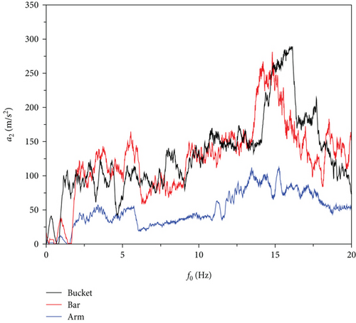
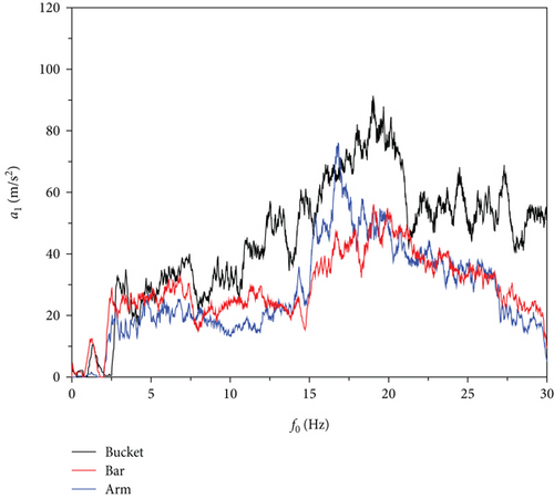
Acceleration harmonic response analysis can reveal the steady-state response characteristics of the excavator arm structure under simple harmonic motion and likewise assess its dynamic stability and resonance risk. The excitation signal in displacement response analysis is also used to analyze the acceleration response of the excavator arm, and the experimental results are shown in Figure 10. From Figure 10, it can be clearly seen that the distribution of acceleration response results and displacement response results are basically the same, and the Y-direction acceleration response is larger than the Z-direction acceleration response, and all the nodes reach the maximum value of acceleration when the frequency is in the vicinity of 15 Hz. In addition, the acceleration of the bucket is the largest, which verifies the accuracy of the simulation results.
5. Conclusion
In this paper, the finite element method was used to carry out a dynamic analysis of the hydraulic excavator arm, combined with modal analysis and harmonic response analysis, and the following main conclusions were drawn: the results of the modal analysis show that the first six orders of the excavator arm under the conditions of the base by the pin constraints have a large difference in the intrinsic frequency of the excavator arm, and the first six orders of the intrinsic frequency are in the range of 7.4231~96.313 Hz. The first sixth-order modal vibration patterns are mainly the left–right swing, up–down swing, left–right torsion, and front–back torsion of the bucket, the hydraulic cylinder, the bucket rod, and the movable arm, etc. The maximum deformation occurs at the bucket position, and the minimum deformation occurs at the base position. Under the sinusoidal load from 0 to 30 Hz with a scanning interval of 1 Hz, the results of the harmonic response analysis of the excavator arm show that the displacement response in the Y-direction is larger, and the overall amplitude of the displacement is the largest at the sinusoidal load of 16 Hz, which is close to the second-order intrinsic frequency of the excavator arm. Therefore, the excavator arm should avoid 16 Hz attachment during the working process to avoid strong vibration phenomenon. Acceleration harmonic response analysis of the overall structure of the excavator arm, the size of the acceleration of the key nodes, and then the vibration transmission path of the excavator arm for the bucket to the bucket bar and then to the arm and finally to the base, to provide a theoretical basis for the further optimization of the mechanical structure of the excavator arm and trajectory control.
Conflicts of Interest
The authors declare no conflicts of interest.
Funding
This research is supported by the Youth Program of the National Natural Science Foundation of China (Grant No. 51805228), the Natural Science Foundation of the Jiangsu Higher Education Institutions of China (Grant Nos. 22KJB460021 and 23KJA460006), and the Changzhou Leading Innovative Talents Introduction and Cultivation Project (Grant Nos. CQ20210093 and CQ20220089).
Acknowledgments
The work in this paper was supported by the Youth Program of the National Natural Science Foundation of China (Grant No. 51805228), the Natural Science Foundation of the Jiangsu Higher Education Institutions of China (Grant Nos. 22KJB460021 and 23KJA460006), and the Changzhou Leading Innovative Talents Introduction and Cultivation Project (Grant Nos. CQ20210093 and CQ20220089).
Open Research
Data Availability Statement
Research data are not shared.


