Theoretical Analysis on Thermodynamic and Economic Performance Improvement in a Supercritical CO2 Cycle by Integrating with Two Novel Double-Effect Absorption Reheat Power Cycles
Abstract
To enhance the overall performance of recompression supercritical carbon dioxide- (sCO2-) based systems, two new double-effect absorption reheat power cycles (DARPC) were developed in this study. These methods are based on the typical absorption power cycle (APC). For the proposed sCO2/DARPC systems, a parametric analysis of the thermodynamic and economic performances, as well as additional parametric optimisations, were performed quantitatively. The results indicate that replacing the APC subsystem with DARPC subsystems can enhance the total function of the sCO2 system even further, owing to the increased H2O vapour created in the separator and the reheating process, which adds to the greater net power output. Furthermore, compared to the DARPC2 subsystem, the DARPC1 subsystem may produce more H2O vapour from the generator and separator, resulting in an increase in net output power. When compared to a single sCO2 power cycle, multiobjective optimisations showed that the sCO2/DARPC1 and sCO2/DARPC2 systems could increase the exergy efficiency by 12.95% and 11.51% and decrease the total product unit cost by 9.67% and 8.37%, respectively. Furthermore, the sCO2/DARPC1 and sCO2/DARPC2 systems can achieve improvements in exergy efficiency of 4.95% and 3.61% and a total product unit cost of 4.52% and 3.15%, respectively, compared with the sCO2/APC system.
1. Introduction
The sustained growth of the global economy has resulted in an ongoing escalation in energy demand, leading to a continuous rise in the utilization of fossil fuels and consequently causing a considerable increase in carbon dioxide emissions [1]. In response to the urgent challenge posed by climate change and the need to mitigate carbon emissions, there is now a critical necessity for transitioning from fossil fuels to renewable energy sources. Because nuclear energy is low-carbon [2], affordable [3], dependable, and ecologically benign, it emits minimal greenhouse gases during its operation and plays an increasingly important role in facilitating the global transition towards sustainable energy. Due to the low corrosion of CO2 on boiler materials, there is no need to use expensive nickel-based alloys, and there is no phase change of CO2 in the supercritical CO2 cycle, no need for equipment such as condensers, and lower investment in initial investment, operation, and maintenance [4, 5]. Furthermore, since CO2 is nontoxic and environmentally friendly, the supercritical CO2 Brayton cycle (sCO2) is thought to be a better option for nuclear reactors [6–8] operating at temperatures between 500°C and 900°C than the steam Rankine cycle [9] and helium Brayton cycle [10]. The sCO2 power cycle also prevents contact between water and Na in nuclear reactors [11]. It is important to note that the CO2 stream needs to be cooled before it enters the compressors [12] in order to benefit from the desirable physical and transport characteristics of the CO2 near the critical point (31.3°C, 7.39 MPa) for lowering the compressor power consumption and thus the higher thermal efficiency [13]. This implies that a considerable percentage of the low-grade thermal energy is wasted in heat sinks [14]. Thus, the reuse of low-grade heat can enhance the performance of sCO2 systems. Consequently, numerous researchers have focused on improving the performance of the sCO2 system by combining it with various waste heat recovery systems [15, 16].
To increase the efficiency of the sCO2 system, a number of low-grade heat reuse technologies have been connected, including transcritical CO2 (tCO2) power cycles, organic Rankine cycles (ORC), and Kalina cycles. According to Akbari and Mahmoudi [17], when isobutane and RC318 are used as the working fluids, respectively, using the ORC to recycle low-grade heat from the recompression sCO2 power cycle can increase the exergy efficiency by 11.7% and lower the total cost per unit of production by 5.7%. According to Fan et al. [18], a solar power tower plant may generate 19% more power annually by utilising an ORC to utilise low-grade heat from a sCO2 gas cooler. In the study by Jankowski et al. [19], multiobjective optimisation was performed utilising the linear weighted sum approach to find the best pinch point temperature difference interval for an ORC powered by a low-grade heat source. According to Li et al. [20], the Kalina cycle can be used as the bottoming cycle for the recompression sCO2 power cycle to reduce exergy destruction by 9.75% and the exergy destruction cost rate by 8.57%. This resulted in an improvement in the exergy efficiency by 8.02% and a decrease in the total product unit cost by 5.50%. To utilise the low-grade heat, Ghaebi et al. [21] used a KC cascade. The findings indicated that the second heat exchanger had the highest rate of energy destruction. Combining tCO2 with sCO2 can increase the thermodynamic performance of the cascade system by 15.35%, according to Wang et al. [22], who used the tCO2 power cycle to capture some of the waste heat produced by the sCO2 power cycle. When compared to a single recompression sCO2 system, Wang et al. [23, 24] discovered that a recompression sCO2/tCO2 system can increase thermal efficiency by 10.12%. Furthermore, compared with the sCO2/ORC system, the sCO2/tCO2 system performed better at low sCO2-compressor pressure ratios. Jankowski et al. [19] compared the thermodynamic and financial performances of an ORC, Kalina cycle, and tCO2 power cycle operated by a low-grade heat source, as compared to Meng et al. [25]. Their findings demonstrated that the Kalina cycle is the most economically efficient and that the tCO2 power cycle may produce the most significant net power.
In addition to the previously discussed power systems, research has been conducted on the absorption power cycle (APC). The LiBr-H2O APC system showed better thermodynamic performance in terms of an improvement of approximately 10% in the exergy efficiency compared to the conventional Rankine cycle, and a better performance benefit could be obtained under a smaller temperature difference between the heat source and heat sink, according to the theoretical analysis results of the thermodynamic performance of the APC system using a LiBr-H2O solution reported by Garcia-Hernando et al. [26]. Their findings suggested that the LiBr-H2O APC system was better suited for lower-temperature heat sources because the ambient coolant temperature typically determines the heat sink temperature. Additionally, Shokati et al. [27] considered the performance of an ammonia-water APC system and noted that, in contrast, the LiBr-H2O APC system was still able to provide greater exergy efficiency. Additionally, Li et al. [28] used the LiBr-H2O and ammonia-water APC systems to repurpose low-grade heat from a recompression sCO2 system. They discovered that, in comparison to the single recompression sCO2 system, the combined sCO2/LiBr-H2O APC system and the sCO2/ammonia-water APC system could improve the thermal efficiency by 5.98% and 5.07% and lower the total product unit cost by 4.24% and 2.19%, respectively. Novotny et al. [29] employed a LiBr solution to convert waste heat into electricity directly in an APC system; the highest total power generation efficiency of the turbine was 0.8% at 150 W. When combined with a solid oxide fuel cell (SOFC), Behzadi et al.’s [30] LiBr-H2O APC system was found to increase exergy efficiency while lowering costs and emissions. Compared to a traditional absorption cycle, Zhang et al. [31] proposed a parallel double-effect LiBr-H2O APC that offered a 41.3% increase in system power generation, a 10.12% decrease in total product unit cost, and a 12.31% gain in exergy efficiency.
To integrate two traditional ammonia-water APC systems, Ma et al. [32] designed a double-effect APC system. This system shared a heat exchanger that functioned as both the boiler and the condenser of the bottoming APC system. In fact, the waste heat of the topping ammonia-water APC system is recovered by the bottoming ammonia-water APC system, which improves the capabilities of the traditional ammonia-water APC system. To produce electrical and cold energy concurrently, Ventas et al. [33] and Mohtaram et al. [34] integrated an APC system with an absorption refrigeration cycle (ARC). This system uses a portion of the working fluid produced by the generator to expand the turbine, which generates power. The remaining working fluid enters the valve, condenser, and evaporator to absorb heat in the evaporator, producing cold energy. This suggests that a portion of the working fluid intended to produce power is used to replace thermal energy, leading to a reduction in the net power output. In comparing the cycling performances of the APC and ORC, Cao et al. [35] discovered that the APC exhibits greater system efficiency and less unit product cost than the ORC, indicating superior cycling performance of the APC relative to the ORC. Based on an APC system, Parikhani et al. [36] and Wang et al. [37] developed combined cooling and power systems. The high-temperature solution from the generator is further used to produce vapour in the separator for the refrigeration cycle [36], or the low-grade heat of these solutions is used to drive the refrigeration cycle [37] for cold energy. In this combined system, all the vapour provided by the generator expands in the turbine to produce power. With a 10.94% gain in exergy efficiency, Zhang et al. [38] created a double-effect APC by recycling the waste heat produced in the sCO2 power cycle.
Based on the research above, it is evident that the recompression sCO2 power cycle is a more viable energy conversion technique for medium-temperature heat sources (500–900°C), like the IV generation of nuclear reactors [6]. It is commonly known that the phase change keeps the temperature of the working fluid constant during vapour formation and condensation in the power cycle that utilises pure fluid, thereby increasing the temperature differential between the working fluid and the heat source or heat sink. However, the temperature of binary mixtures changes during heat transfer from the binary mixtures to the heat source or heat sink, which is related to variations in the concentrations of the binary mixtures. This helps improve the temperature match between the working fluid and the heat source or heat sink. The thermodynamic irreversibility, exergy destruction within heat exchangers, and heat transfer performance can be enhanced by these temperature-glide matching qualities. Thus, it makes more sense to use an APC system with binary mixes, such as a LiBr-H2O solution, to harness low-grade heat sources, including the waste heat from the recompression sCO2 system, which can reach temperatures as low as 120°C [39]. Li et al. [28] studied how integration with an APC system can enhance the performance of the recompression sCO2 power cycle. The fundamental design of this APC system can be improved to make greater use of waste heat from the sCO2 recompression system. Consequently, two sophisticated and innovative double-effect absorption reheat power cycles (DARPC) were developed.
This study focused on improving the performance of the recompression sCO2 system. The LiBr-H2O solution was selected as the operating fluid for the two DARPC systems researched in this paper because it lowers the backpressure of the turbine during the absorption-condensation process with traditional coolants [26], which enhances the turbine power output of the APC systems. It has also been reported to be a preferable operating fluid for APC systems based on the reviews above. The proposed DARPC system has one generator that produces vapour with high temperature and pressure to expand in the high-pressure turbine and one separator that further produces additional vapour with medium temperature and pressure to expand in the low-pressure turbine. This is in contrast to the ammonia-water DAPC system described in the literature [32], where an ammonia-water APC system was used to recover the waste heat from the other ammonia-water APC system, and the two ammonia-water APC systems shared the heat exchanger as a generator and absorber. In addition, there is a heat exchanger in which the heat of the LiBr-H2O solution entering the generator is transmitted to the expanded vapour exiting the high-pressure turbine, allowing it to expand further in the low-pressure turbine. To determine the effect of various decision variables on the performance of the sCO2/DARPC system, a parametric study of the thermodynamic and economic performances of the two proposed recompression sCO2/DARPC systems was conducted. In addition, a comparative analysis, together with single-objective and multiobjective optimisations, is conducted for two sCO2/DARPC systems, the sCO2/APC system and the standalone sCO2 system, to demonstrate the superiority and potential of the performance improvement of the sCO2 system by integration with the DARPC systems. The findings of this study may offer theoretical groundwork for the future development of a workable power system for nuclear power plants.
2. System Description and Assumptions
2.1. The sCO2/DARPC System Description
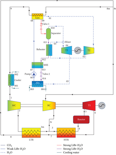
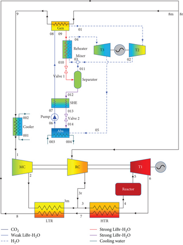
The schematic designs of the two combined recompression sCO2/DARPC systems are shown in Figure 1. It is clear that the DARPC systems are utilised to recycle waste heat from the sCO2 stream that enters the cooler of the sCO2 power cycle used for recompression. The recompression sCO2 power cycle has already been discussed in many works, and thus its layout and operation processes are not discussed in this work. The novelty of this work focused on the development of two novel DARPC systems. The reheating process is utilised for two novel DARPC systems to further enhance the thermodynamic performance of the bottoming DARPC systems, and moreover, more additional heat can be recovered from the topping sCO2 power cycle to reduce the heat dissipation loss within the sCO2 cooler. The difference between the DARPC1 and DARPC2 is the arrangement of the reheater, and the detailed operational processes of the bottoming DARPC systems can be found below. A generator (Gen), two turbines (T2 and T3), an absorber (Abs), a pump, a solution heat exchanger (SHE), two throttle valves (valve 1 and valve 2), a separator, and a reheater are all part of bottoming DARPC systems.
2.1.1. The DARPC1 System
Heat from the sCO2 stream passing through the generator is absorbed by the weak LiBr-H2O solution (stream 08) as it enters the generator. A portion of the H2O is extracted from the weak LiBr-H2O solution during this heat absorption process, producing the H2O vapour (stream 01) and the strong LiBr-H2O solution (stream 09). Valve 1 was then used to throttle stream 09 and separate it into two streams: stream 010, which had more H2O vapour, and stream 011, which was a strong LiBr-H2O solution with a more significant LiBr mass fraction in the separator.
Meanwhile, the pump and energy generator are powered by stream 01, which enters turbine 2 and expands inside the revolving turbomachinery. Following the expansion, stream 02 absorbs heat in the reheater before streams 03 and 010 are combined. The mixture (stream 04) then expands in turbine 3 to power the generator that generates electricity. It should be mentioned that in this investigation, the working fluid pressure reductions across turbines 2 and 3 are identical. Stream 011 gradually liberates heat in the SHE and reheater before being throttled over valve 2 to form stream 014. A weak LiBr-H2O solution (stream 06) was created in the absorber when stream 014 absorbed the expanded stream 05 and cooled to a saturated liquid state. Ultimately, the pump pressurises stream 06, which subsequently absorbs heat from the SHE to become stream 08, which enters the generator.
2.1.2. DARPC2 System
In contrast to the valve, separator, and reheater in that order in the DARPC1 system, stream 09 leaves the generator of the DARPC2 system and enters the reheater, valve, and separator in that order. Additionally, the vapour generated by the separator combined with the expanded vapour entered the reheater rather than leaving it. The other operational procedures of the DARPC1 system remain the same.
2.2. The sCO2/DARPC System Assumptions
- (1)
The sCO2/DARPC system operated under stable conditions
- (2)
The fluctuations in the kinetic and potential energies of the working fluid are disregarded
- (3)
Pressure drop and heat loss of the working fluid as it moves over the pipes and heat exchangers
- (4)
The processes of the LiBr-H2O solution passing through valves 1 and 2 were isenthalpic
- (5)
The saturated solutions are the LiBr-H2O solutions that come out of the generator, separator, and absorber
3. Mathematical Models and Performance Standard
3.1. Economic Model of the sCO2/DARPC Systems
| System components | Economic parameters and cost functions |
|---|---|
| Reactor | Zreac = 283 × Qreac |
| Turbine |
|
| Compressor |
|
| Pump |
|
| HTR, LTR, and cooler | Zk = 30 × Massk |
| Gen, Abs, SHE, and reheater |
|
3.2. Performance Criteria
4. Model Validations
To demonstrate the significance and dependability of the research, validations of the mathematical models based on the MATLAB program were performed to check the capability of the sCO2/DARPC system. The physical characteristics of CO2 and H2O were obtained using REFPROP NIST 9.1, and the physical characteristics of the LiBr-H2O solution were acquired by solving a related set of empirical equations provided in Refs. [45, 46]. Additionally, after consulting Ref. [47], the crystallisation characteristics of the LiBr-H2O solution are also considered. As shown in Table 2, it should be noted that verification was performed in order to compare the system performance with the results published by Li et al. [28] for the recompression sCO2/APC system with the working fluid of the LiBr-H2O solution. As shown, there was a minimal discrepancy between the available data and the expected outcomes of the current investigations, suggesting that mathematical models are reliable means of forecasting the quantitative performance of the sCO2/DARPC system.
| Items | Reference [28] | Present work |
|---|---|---|
| Input parameters | ||
| (°C) | 550 | 550 |
| PRc | 3.346 | 3.346 |
| Pgen (kPa) | 40.88 | 40.88 |
| CLiBr (%) | 40.1 | 40.1 |
| Tgen (°C) | 120.0 | 120.0 |
| Tabs (°C) | 40.01 | 40.01 |
| Output parameters | ||
| Wnet (MW) | 253.39 | 253.378 |
| ηth (%) | 42.23 | 42.230 |
| ηex (%) | 57.37 | 57.366 |
5. Results and Discussion
This study is aimed at demonstrating the superior performance enhancement of the sCO2 system by integrating it with the proposed DARPC systems. Accordingly, from the perspectives of thermodynamics and economics, parametric analysis and comparative studies were conducted for the two sCO2/DARPC systems. Subsequently, additional parametric optimisations and performance comparisons between the sCO2/DARPC, sCO2/APC, and standalone sCO2 systems were conducted.
5.1. Parametric Analysis
This section presents a parametric analysis to examine how the choice factors affect the thermodynamic and financial performance of the suggested sCO2/DARPC systems. The highest cycle pressure and temperature for these combined systems were determined by the sCO2 turbine inlet temperature (T5) and the sCO2 compressor pressure ratio (PRc). Additionally, the mass flow rate of the working fluid in the DARPC system and the heat recovery in the generator were significantly affected by the generator outlet temperature (Tgen) and pump outlet pressure (Ppump). Furthermore, the mass flow rate of the H2O vapour and the backpressure of the DARPC turbines were significantly affected by the absorber outlet temperature (Tabs) and the LiBr mass fraction of the weak LiBr-H2O solution entering the absorber (Cweak). Subsequently, parametric analyses were performed using these six decision parameters.
5.1.1. Impact of the Turbine Inlet Temperature and the sCO2 Compressor Pressure Ratio on the Performance of the System
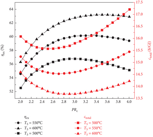
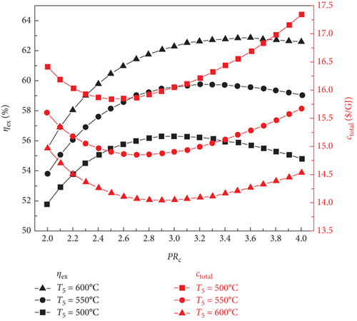
Figure 2 illustrates the variations in the sCO2/DARPC1 system, the exergy efficiency of the sCO2/DARPC2 system, and the total product unit cost with changes in the sCO2 compressor pressure ratio (2.0-4.0) and sCO2 turbine inlet temperature (500, 550, and 600°C). It is evident that when the sCO2 compressor pressure ratio is increased, the exergy efficiency increases until a maximum exergy efficiency is reached. At this point, it decreases for both sCO2/DARPC systems. In addition, sCO2/DARPC systems operating at a higher sCO2 turbine inlet temperature demonstrated greater exergy efficiency. In contrast, as the sCO2 compressor pressure ratio and turbine inlet temperature increased, the variation pattern of the total product unit cost reversed. Furthermore, a close examination revealed that the optimal sCO2 compressor pressure ratio was displayed by sCO2/DARPC systems running at a higher sCO2 turbine inlet temperature. When Figures 2(a) and 2(b) are compared, it can be seen that the sCO2/DARPC1 system offers a higher exergy efficiency and a lower total product unit cost than the sCO2/DARPC2 system.
The fluctuations in the mass flow rate and net power output of the working fluid with respect to the sCO2 compressor pressure ratio at various sCO2 turbine inlet temperatures for the two sCO2/DARPC systems are shown in Figure 3. The net power output of the topping sCO2 subsystem rises with the sCO2 compressor pressure ratio until a peak is reached. At this point, it begins to decrease, as Figure 3(a) illustrates. This is because an increased cycle pressure results in increased power generation from the turbine as well as increased power consumption from the compressors. Additionally, with a fixed reactor heat input and constant sCO2 turbine inlet temperature, the mass flow rate of sCO2 falls with an increase in the sCO2 compressor pressure ratio.
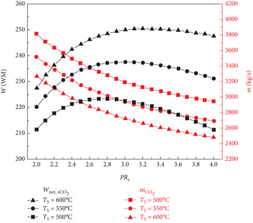
It should be emphasized that the lower mass flow rate of the sCO2 stream is produced by the sCO2 subsystem working at a higher turbine inlet temperature because the sCO2 flowing across the reactor under a constant heat input has a higher temperature rise. Additionally, the higher work output of the sCO2 turbine is supported by the increased turbine inlet temperature, and the reduction in compressor consumption results from the sCO2 passing through them at a lower mass flow rate. Thus, an increased net power output is produced by the sCO2 subsystem running at a higher turbine input temperature.
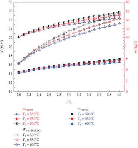
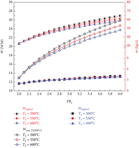
The impacts of the sCO2 turbine inlet temperature and sCO2 compressor pressure ratio on the vapour mass flow rate and net power output for the DARPC1 and DARPC2 subsystems that are bottoming out are shown in Figures 3(b) and 3(c), respectively. The temperature of the sCO2 stream passing through the generator rises with an increase in the sCO2 compressor pressure ratio, which aids the heat recovery of the generator. As a result, the mass flow rate of the LiBr-H2O solution used to recycle the low-grade heat increased as the pressure ratio of the sCO2 compressor increased. This leads to a corresponding increase in the amount of H2O vapour that is separated from the LiBr-H2O solution in the separator (mvapor2) and generator (mvapor1), which results in a higher net power output of the DARPC subsystems. In addition, when the combined systems operate at a higher sCO2 turbine inlet temperature, less sCO2 flows through the generator, resulting in a lower heat input from the sCO2 stream in the generator. Due to the decreased mass flow rate of LiBr-H2O solution working in the bottoming cycle, the generator and separator create less H2O vapour, which results in a lower net power output of the DARPC subsystems.
Furthermore, a comparison of the two DARPC subsystems shows that, compared to the DARPC2 subsystem, the DARPC1 subsystem can supply more H2O vapour passing through turbines 2 and 3. This can result in higher net power production. For the two DARPC subsystems, higher power output was obtained by reheating the expanded H2O vapour in the reheater and producing extra H2O vapour in the separator. It should be noted that the high-temperature LiBr-H2O solution that is leaving the generator is the source of the heat utilised to produce the extra H2O vapour and reheat the enlarged H2O vapour. This indicates that more heat is absorbed by the LiBr-H2O solution in the generator, whereas less heat from the sCO2 stream is emitted in the cooler. Consequently, the bottoming cycle used more LiBr-H2O solution. This increases the amount of H2O vapour produced in the separator and generator.
Furthermore, the DARPC1 subsystem generator recovers more heat than the DARPC2 subsystem, which helps produce more H2O vapour and higher power output. It is commonly known that a higher temperature and fixed pressure in the separator facilitate the more straightforward extraction of H2O vapour from the LiBr-H2O solution. Because the LiBr-H2O solution exiting the generator flows directly across the valve and enters the separator of the DARPC1 subsystem, it is evident that the temperature of the LiBr-H2O solution in the separator is higher for the DARPC1 subsystem than for the DARPC2 subsystem. In the DARPC2 subsystem, heat was released into the reheater before the solution flowed through the valve and separator. As a result, the H2O vapour generated in the DARPC1 subsystem separator had a higher mass flow rate than that in the DARPC2 subsystem. It is noteworthy that the DARPC2 subsystem has a higher reheating temperature than the DARPC1 subsystem. This suggests that the DARPC2 subsystem can achieve a higher turbine 3 power output per unit operating flow rate. Nonetheless, the mass flow rate of H2O vapour through turbines 2 and 3 in the DARPC1 subsystem is greater than that in the DARPC2 subsystem, and the higher working fluid flow rate has a more significant impact on power production than the increased reheat temperature. In line with this, the DARPC1 subsystem had a larger net power output than the DARPC2 subsystem. Therefore, the sCO2/DARPC1 system can achieve higher exergy efficiency and lower overall product unit cost than the sCO2/DARPC2 system.
As can be observed from the above discussion, the topping sCO2 power cycle dominates the variation trend of the net power output of the combined sCO2/DARPC systems with varied sCO2 compressor pressure ratios at different sCO2 turbine inlet temperatures, and the net power output of the bottoming DARPC subsystems can further increase the magnitude of the net power output for the combined systems. Thus, the net power output of the combined system increased as the compressor pressure ratio increased, until the best compressor pressure ratio was discovered to produce the highest net power output. This optimal value is greater than that of the sCO2 subsystem because the power output of the DARPC subsystem increases with the compressor pressure ratio. Additionally, the combined system operating at a higher temperature for the sCO2 turbine inlet produces a higher net power output. However, the difference in net power output between the different turbine inlet temperatures is less than that of the sCO2 subsystem, which can be attributed to the lower power output of the DARPC subsystems at higher temperatures for the sCO2 turbine inlet. Thus, for the power systems, the exergy efficiency variation trend was the same as the net power output trend.
As the sCO2 compressor pressure ratio increased, the overall investment in the combined system increased. When the sCO2 compressor pressure ratio increases, the total product unit cost decreases until the effect of the increased total investment overrides the increase in the net power output. At this point, it begins to increase. In addition, when the temperature of the sCO2 turbine inlet increases, the mass flow rate of the sCO2 stream reduces, thereby lowering the overall investment. Consequently, the combined system operating under a larger sCO2 turbine inlet temperature exhibits improved economic performance in terms of reduced total product unit cost owing to the higher net power output and lower total investment.
5.1.2. Impact of Generator Output Temperature and Pump Outlet Pressure on System Performance
Figure 4 shows how the exergy efficiency and total product unit cost of the sCO2/DARPC1 system and sCO2/DARPC2 system vary depending on the generator outlet temperature (115, 120, and 125°C) and pump outlet pressure (40, 90, and 100 kPa). The exergy efficiency of the two sCO2/DARPC systems was shown to improve with an increase in the pump outlet pressure until the pump outlet pressure was optimised to produce the highest exergy efficiency. At that point, it began to decrease. However, with the increase in pump outlet pressure, the overall product unit cost shows the opposite trend. Because the impacts of the generator outlet temperature and pump outlet pressure on the thermodynamic and financial performance of the topping sCO2 subsystem can be disregarded, this occurrence depends on the variation trend of net power production for the bottoming DARPC subsystems.
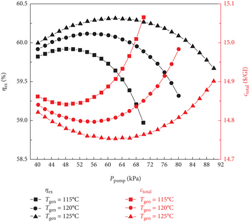

Naturally, while the temperature and concentration of the LiBr-H2O solution remained constant, it became more challenging to extract H2O vapour from the solution in the generator at higher pressures. As a result, as the pump outlet pressure increased, the mass flow rate of the vapour departing from the generator decreased, as illustrated in Figure 5. However, when the pump outlet pressure increases, the mass flow rate of the H2O vapour generated in the separator also increases. This is because the ability of the separator to separate H2O vapour from the LiBr-H2O solution is facilitated by the more substantial mass fraction of H2O in the strong LiBr-H2O solution coming out of the generator. It is commonly known that a higher turbine work output per unit working flow rate can be achieved when the pressure drop of the H2O vapour passing through the turbine increases. Therefore, the work output of turbine 2 increases with increasing pump outlet pressure until the influence of the decreasing vapour mass flow rate on the work output of turbine 2 is greater than the growing turbine intake pressure. At this point, it begins to decline.
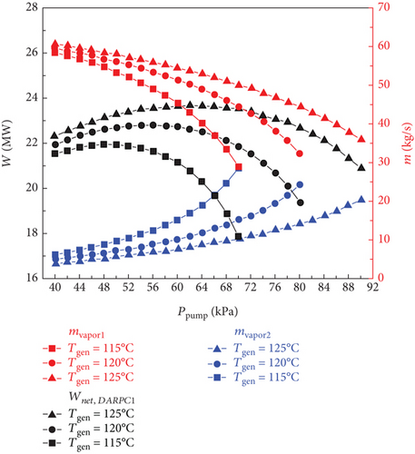
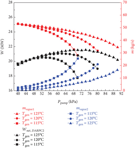
Furthermore, it should be mentioned that the mass flow rate of H2O vapour flowing across turbine 3 slightly decreased as the pump outlet pressure increased because the mass flow rate of vapour exiting the generator and separator exhibited opposite fluctuation trends. It ought to be noticed that the little decline in the temperature of the vapour stream entering turbine 3 of the DARPC1 subsystem is caused by the higher temperature decrease of the fluid being throttled in the valve under the higher pressure decrease. Consequently, for the DARPC1 subsystem, the work output of turbine 3 increased as the pump outlet pressure increased, until the effect of the growing turbine 3 inlet pressure on the work output was less pronounced than the effect of the gradually declining mass flow rate and temperature of the vapour entering turbine 3. At that point, it started to decline. However, because the generator outlet temperature was equal to the hot-side inlet temperature of the reheater, the temperature of the vapour entering turbine 3 of the DARPC2 subsystem was fixed. As a result, within the variation range examined here, the work output of turbine 3 for the DARPC2 subsystem increased as the pump outlet pressure increased. As pump outlet pressure rises, the net power output of the DARPC subsystems rises until the maximum net power output is achieved, at which point it begins to decline, as illustrated in Figure 5 when taking into account the power output variation trend for turbines 2 and 3. Furthermore, DARPC2’s ideal pump outlet pressure is greater than DARPC1’s.
It is commonly known that at higher temperatures when the concentration and pressure of the LiBr-H2O solution remain constant, it is simpler to separate H2O vapour from the solution. Consequently, more H2O vapour can depart the generator, whereas the DARPC subsystem operates at a higher generator output temperature. However, at lower pump outlet pressures, the effect of the generator outlet temperature on the mass flow rate of the H2O vapour exiting the generator became less pronounced. In fact, an intriguing phenomenon can be observed where the DARPC2 subsystem exhibits a reverse variation trend with increasing generator outlet temperature under low pump outlet pressure. This is due to the fact that at higher pressures, the LiBr-H2O solution exhibits a lower saturation concentration, closely resembling the concentration of the weaker LiBr-H2O solution. As a result, a modest increase in the saturation concentration of the temperature rise significantly increased the amount of H2O vapour. The separation of H2O vapour was slightly affected by the temperature-rise-induced enhancement of the saturation concentration because, under low pressure, the LiBr-H2O solution had a high saturation concentration that was far from the concentration of the weak LiBr-H2O solution. Additionally, when the temperature of the generator outlet rises, the LiBr-H2O solution flowing across the generator also rises in temperature. Consequently, the mass flow rate of the LiBr-H2O solution decreased, which resulted in a slight reduction in the mass flow rate of H2O vapour, leaving the generator of the DARPC2 subsystem under low pump outlet pressure.
Furthermore, because of the higher concentration and lower mass flow rate of the LiBr-H2O solution entering the separator, the mass flow rate of the H2O vapour exiting the separator decreased as the generator output temperature increased. Additionally, it should be noted that the total mass flow rate of the H2O vapour flowing across turbine 3 does not change significantly as the generator outlet temperature increases because the increase in the H2O vapour mass flow rate leaving the generator almost compensates for the decrease in the H2O vapour mass flow rate leaving the separator. This shows that the work output of turbine 3 varies very little with an increase in the generator outlet temperature and that the work output of turbine 2 dominates the change in the net power output of the DARPC subsystems. With the exception of the DARPC2 subsystem when the pump outlet pressure is low, as illustrated in Figure 5, the DARPC subsystem functioning at a higher generator outlet temperature provides a higher net power production. Accordingly, as shown in Figure 4, the variation trend of the total product unit cost was reversed, and the exergy efficiency of the combined systems operating under a higher generator outlet temperature was higher, with the exception of the sCO2/DARPC2 subsystem under low pump outlet pressure.
The DARPC1 subsystem can provide a higher mass flow rate of H2O vapour exiting the generator and separator and, thus, a higher net power output, compared with the DARPC2 subsystem, under the variation ranges of the pump outlet pressure and the generator outlet temperature studied here, according to comparative studies on the thermodynamic and economic performance of the sCO2/DARPC1 and sCO2/DARPC2 systems. In terms of increased exergy efficiency and decreased total product unit cost, the combination sCO2/DARPC1 system outperformed the combined sCO2/DARPC2 system overall.
5.1.3. Impact of LiBr Mass Fraction and Absorber Output Temperature on System Performance
The impact of the LiBr mass fraction (0.4, 0.45, and 0.5) and absorber output temperature (35–45°C) on the thermodynamic and financial performance of the sCO2/DARPC1 and sCO2/DARPC2 systems is examined in this section. The LiBr-H2O solution exhibited a higher saturation pressure at a fixed concentration and temperature. This demonstrates that with an increase in the absorber outlet temperature, the pressure of the saturated LiBr-H2O solution exiting the absorber increases; thus, the backpressure of the DARPC turbines increases. Consequently, the pressure and enthalpy drops of the H2O vapour expanding through these turbines were reduced, which in turn lowered the unit working flow rate of the work output of these turbines. Furthermore, when the temperature of the LiBr-H2O solution entering the generator rises, the heat input of the sCO2 stream running through it drops, resulting in a decrease in the mass flow rate of H2O vapour exiting the generator and separator. Consequently, as illustrated in Figure 6, as the absorber outlet temperature increased, the total work output of the DARPC turbines decreased, and the net power output of the DARPC subsystems also reduced. Notably, the LiBr mass fraction and absorber outlet temperature had little effect on the thermodynamic and financial performances of the topping sCO2 power cycle. Consequently, the net power output of the bottoming DARPC subsystems dominated the variation trend of the combined sCO2/DARPC system exergy efficiency and total product unit cost with different absorber outlet temperatures and LiBr mass fractions. Consequently, as illustrated in Figure 7, the exergy efficiency of the coupled sCO2/DARPC systems decreased linearly as the temperature of the absorber output increased. However, the overall product unit cost variation trend was inverted.
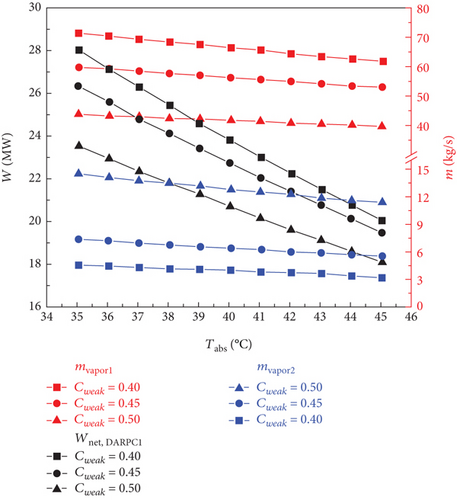

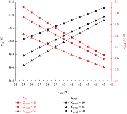
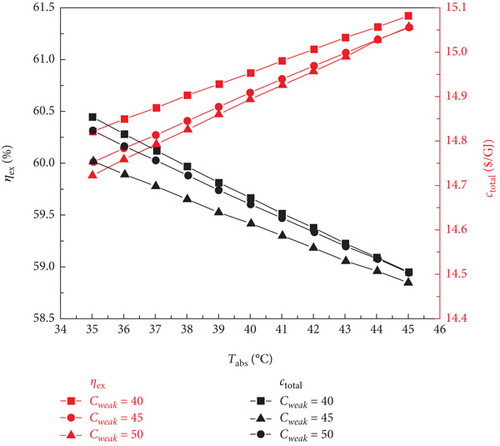
As Figure 6 illustrates, it is well known that a lower mass fraction of LiBr in a weak LiBr-H2O solution corresponds to a more significant mass fraction of H2O, which helps separate more H2O vapour from the weak LiBr-H2O solution before it enters the generator. This is advantageous for increasing the work output of turbine 2. In contrast, less H2O vapour was created in the separator because more H2O vapour was previously dissociated from the LiBr-H2O solution in the generator. Nonetheless, despite the reduced LiBr mass fraction, the overall mass flow rate of the H2O vapour passing through turbine 3 was still higher, increasing the turbine work output. Furthermore, the saturation pressure of the saturated, weak LiBr-H2O solution was strongly influenced by the mass fraction of LiBr. A LiBr-H2O solution, which has a lower LiBr mass fraction and is maintained at a constant temperature, generally exhibits a higher saturation pressure. Consequently, the pressure and enthalpy drops of the H2O vapour passing through the DARPC turbines decreased, which lowered the work output of these turbines per unit mass flow rate. It is noteworthy that the increased vapour mass flow rate, rather than the increase in turbine backpressure, had a greater effect on the work output of these turbines when the LiBr mass fraction fell. Consequently, the net power output of the DARPC subsystem rises.
However, when the temperature of the absorber outlet increased, the turbine backpressure increased, lowering the pressure and enthalpy of the working fluid that passed through the turbines. This suggests that a further increase in turbine backpressure can result in a more notable decrease in turbine work production at a higher absorber outlet temperature. This suggests that when the temperature of the absorber outlet rises, the higher turbine backpressure, caused by a lower LiBr mass fraction, had a progressively more significant impact on the turbine work output than the increased vapour mass flow rate, also a result of the lower LiBr mass fraction. It is therefore notable that for two LiBr mass fractions of 0.40 and 0.45, the net power outputs of the DARPC2 subsystem are practically comparable, despite the absorber outlet temperature rising to 45°C. This is due to the fact that when the absorber outlet temperature rose, the disparity between the net power outputs of the DARPC subsystems under various LiBr mass fractions decreased. Thus, for a given LiBr mass fraction, the absorber output temperature increases with decreasing exergy efficiency and total product unit cost, as Figure 7 illustrates. The combined sCO2/DARPC systems with a lower LiBr mass fraction provided greater exergy efficiency and reduced total product unit cost. The DARPC2 subsystem shows almost the same exergy efficiency and the total product unit cost for two LiBr mass fractions of 0.40 and 0.45 when the absorber outlet temperature rises to 45°C. It is evident that increasing the absorber outlet temperature results in the opposite trend of variation in the exergy efficiency and total product unit cost with different LiBr mass fractions.
Compared to the combined sCO2/DARPC2 system, the combined sCO2/DARPC1 system offers a higher mass flow rate of H2O vapour produced in the generator and separator and, consequently, a higher net power output. This was based on a comparative analysis of the overall performances of the two sCO2/DARPC systems under the variation ranges of the absorber outlet temperature and LiBr mass fractions studied here. As a result, compared to the sCO2/DARPC2 system, the sCO2/DARPC1 system offers higher exergy efficiency and lower total product unit cost.
5.2. Single-Objective Optimisation for Different sCO2-Based Power Systems
The single recompression sCO2 system, recompression sCO2/APC system, recompression sCO2/DARPC1 system, and recompression sCO2/DARPC2 system were all subjected to single-objective optimisations and comparative analyses to determine the best decision parameters for maximising exergy efficiency or minimising the total product unit cost and to demonstrate the superior overall performance of the suggested recompression sCO2/DARPC systems. It ought to be noticed that the structure of the recompression sCO2/APC system used as a baseline is the same as that reported by Li et al. [28], who enhanced the performance of the sCO2 system using a basic APC system. Additionally, the structure of the sCO2 system under study was the same for both the topping sCO2 subsystem and the single recompression system. A genetic algorithm (GA), which is a popular, dependable, and efficient optimisation algorithm, was utilised to perform these single-objective optimisations. To replicate the natural evolution process, the GA optimisation process involves the generation of a population, fitness, selection, crossover, and mutation. The optimisation process ends when the new population satisfies the necessary termination criteria to produce the best outcome. Tables 3 and 4 display the optimisation results of the sCO2-based power systems for optimising exergy efficiency and decreasing the cost of the entire product unit, respectively.
| Items | sCO2 system | sCO2/APC system | sCO2/DARPC1 system | sCO2/DARPC2 system |
|---|---|---|---|---|
| PRc | 3.002 | 3.3571 | 3.2659 | 3.3682 |
| T5 (°C) | 550 | 550 | 550 | 550 |
| Pp (kPa) | / | 54.2627 | 77.7568 | 87.7121 |
| Tgen (°C) | / | 125 | 125 | 125 |
| Tabs (°C) | / | 35 | 35 | 35 |
| Cweak | / | 0.4 | 0.4 | 0.4 |
| Wnet (MW) | 237.6034 | 255.7599 | 268.2195 | 264.9514 |
| ηth (%) | 39.6006 | 42.6267 | 44.7032 | 44.1586 |
| ηex (%) | 54.8353 | 59.0255 | 61.9010 | 61.1468 |
| ctotal ($/GJ) | 16.0812 | 15.2781 | 14.5766 | 14.8003 |
| Items | sCO2 system | sCO2/APC system | sCO2/DARPC1 system | sCO2/DARPC2 system |
|---|---|---|---|---|
| PRc | 2.5704 | 2.7601 | 2.6985 | 2.7601 |
| T5 (°C) | 550 | 550 | 550 | 550 |
| Pp (kPa) | / | 44.2801 | 73.2383 | 84.8895 |
| Tgen (°C) | / | 125 | 125 | 125 |
| Tabs (°C) | / | 35 | 35 | 35 |
| Cweak | / | 0.4 | 0.4 | 0.4 |
| Wnet (MW) | 235.3865 | 252.6094 | 265.2858 | 262.0186 |
| ηth (%) | 39.2311 | 42.1016 | 44.2143 | 43.6698 |
| ηex (%) | 54.3237 | 58.2985 | 61.2240 | 60.4699 |
| ctotal ($/GJ) | 15.9115 | 15.0566 | 14.3727 | 14.5706 |
The overall performance of the single sCO2 system can be improved using the APC subsystem, as shown in Tables 3 and 4, and the APC subsystem can be replaced with the DARPC subsystems to significantly improve the system’s thermodynamic and financial performance. According to the optimisation results for the maximum exergy efficiency, as compared to a single sCO2 system, the sCO2/DARPC1 and sCO2/DARPC2 systems may increase the exergy efficiency by 12.89% and 11.51%, respectively, and reduce the total product-unit cost by 9.36% and 7.97%, respectively. Additionally, the sCO2/DARPC1 system and sCO2/DARPC2 system achieved improvements in exergy efficiency and total product unit cost of 4.87% and 3.59%, respectively, compared to the sCO2/APC system.
When compared to a single sCO2 system, the sCO2/DARPC1 and sCO2/DARPC2 systems may still improve exergy efficiency by 12.70% and 11.31% and decrease total product unit cost by 9.67% and 8.43%, respectively, in the optimisation findings for reducing the total product unit cost. Furthermore, the sCO2/DARPC1 and sCO2/DARPC2 systems achieved improvements in exergy efficiency and total product unit cost of 5.02% and 3.72% and 4.54% and 3.23%, respectively, when compared to the sCO2/APC system. The APC subsystems enhance the optimal sCO2 compressor pressure ratio, thereby improving sCO2 system performance, while replacing the APC subsystem with the DARPC subsystem raises the optimal pump outlet pressure, aligning with the operational needs of the sCO2/DARPC system, as evidenced by a comparative analysis of the optimal parameters of the single-objective optimisations for these sCO2-based power systems. For the various power systems examined here, other optimum parameters, for instance, the ideal temperature of the sCO2 turbine inlet, the temperature at which the generator and absorber exit, and the LiBr mass fraction, remain the same. Furthermore, a comparative analysis of the optimisation findings showed that the ideal sCO2 compressor ratio and pump outlet pressure for optimum exergy efficiency were higher than those for the lowest possible cost per unit of production. This indicates that the power systems under study cannot simultaneously offer the lowest possible total product unit cost and the highest possible exergy efficiency at the same time. To meet the various application requirements, it is necessary to achieve numerous compromises between maximum exergy efficiency and minimum total product unit cost. For this reason, multiobjective optimisations are performed in the following section to determine the number of optimal Pareto front solutions.
5.3. Multiobjective Optimisation for Different sCO2-Based Power Systems
For the four sCO2-based power systems, multiobjective optimisations were conducted using the NSGA-II approach to produce a set of solutions that compromise between the maximum exergy efficiency and the minimum total product unit cost. The variation ranges of the decision parameters corresponded to those of the aforementioned single-objective optimisations. The best Pareto front sets of the multiobjective optimisation results are shown in Figure 8, and it is clear that the cost of the entire product unit increases as the exergy efficiency increases. Consequently, to meet different application requirements, power systems with better thermodynamic or economic performances may operate under different conditions based on these optimal Pareto front sets. However, these power systems compromise their economic performance to operate.
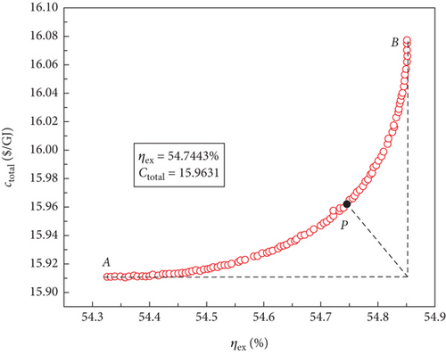
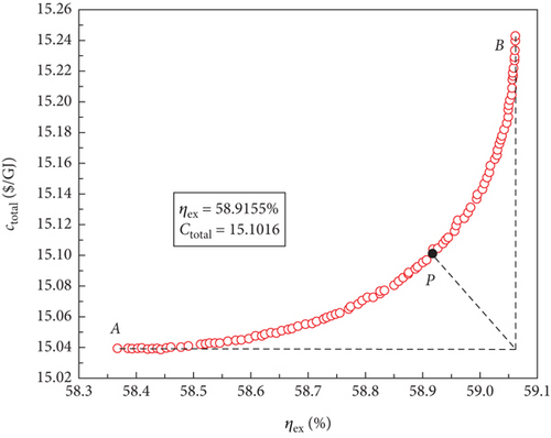
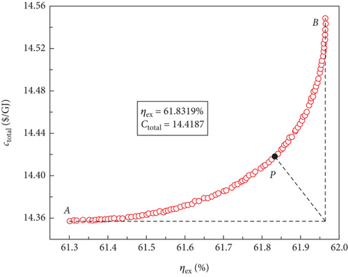
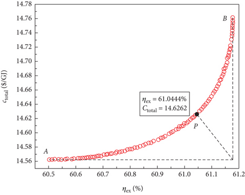
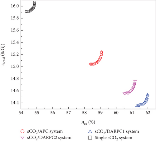
The optimal Pareto front sets curve for the sCO2/DARPC1 system, as depicted in Figure 8(e), lies closest to the lower right corner of the graph, indicating the maximum exergy efficiency and lowest total product unit cost of the system. The curves representing the sCO2/DARPC2, sCO2/APC, and single sCO2 systems were next to each other. This suggests that in terms of exergy efficiency and total product unit cost, the sCO2/DARPC1 system performed the best overall, followed by the sCO2/DARPC2, sCO2/APC, and single sCO2 systems. Pareto-optimal solutions must be found to carry out a more thorough quantitative comparison of the multiobjective optimisation outcomes for the four power systems. The point “P” in these graphs, which is the closest to the ideal point “O” with the maximum exergy efficiency and the lowest total product unit cost displayed in the optimal Pareto front sets, represents the Pareto-optimal solutions, as illustrated in Figures 8(a), 8(b), 8(c), and 8(d). The sCO2/DARPC1 and sCO2/DARPC2 systems increased the exergy efficiency by 12.95% and 11.51%, respectively, and reduced the total product unit cost by 9.67% and 8.37%, respectively, compared with the single sCO2 system, according to a comparison of the Pareto-optimal solution among the four sCO2-based systems. Furthermore, the sCO2/DARPC1 system and sCO2/DARPC2 system achieved improvements in exergy efficiency and total product unit cost of 4.95% and 3.61%, respectively, compared with the sCO2/APC system.
6. Conclusions
- (i)
More H2O vapour expanded through the DARPC1 turbines, producing a higher net power output, even though the reheating temperature was lower than that of the bottoming DARPC2 subsystem. As a result, compared to the sCO2/DARPC2 system, the sCO2/DARPC1 system performed better thermodynamically and economically
- (ii)
The ideal sCO2 compressor pressure ratio and pump outlet pressure were determined for both sCO2/DARPC systems to yield the highest exergy efficiency or the lowest overall product unit cost. Furthermore, greater thermodynamic and economic performance is demonstrated by sCO2/DARPC systems that operate at higher temperatures for the turbine inlet and generator outlet or at lower temperatures for the absorber outlet and LiBr mass fraction
- (iii)
Interestingly, when the pump outlet pressure was reduced, the differences in the energy efficiencies and total product unit costs of the sCO2/DARPC systems operating at different generator outlet temperatures decreased. Similarly, when the absorber outlet temperature increased, the performance difference under varying LiBr mass fractions decreased
- (iv)
According to the multiobjective optimisation results, when compared to a single sCO2 system, the sCO2/DARPC1 and sCO2/DARPC2 systems may increase the exergy efficiency by 12.95% and 11.51%, respectively, and decrease the overall cost of the product unit by 9.67% and 8.37%, respectively. Furthermore, the sCO2/DARPC1 system and sCO2/DARPC2 system achieved improvements in exergy efficiency and total product unit cost of 4.95% and 3.61%, respectively, compared with the sCO2/APC system
In fact, this is a preliminary work on the concept design of two novel sCO2-based power cycles. Although there are a number of challenges that need to be solved for the real application, such as the design, manufacture, and maintenance of the system’s main components and the control and safety strategy of the proposed systems, the proposed sCO2-based power cycle has a good application prospect. Apart from the application in nuclear power plants discussed in this work, the proposed system can also be applied in coal-fired power plants, concentrated solar power plants, industrial waste heat recovery with high and medium temperatures, and fuel cells. This is due to the fact that the proposed system consists of the topping recompression sCO2 and the bottoming DARPC systems, and correspondingly, the proposed system has the same application potential but better overall performance compared with the sCO2 power cycle.
Nomenclature
-
- A:
-
- Heat transfer area (m2)
-
- C:
-
- Solution concentration (%)
-
- :
-
- Cost rate ($·h-1)
-
- c:
-
- Cost per unit exergy ($·GJ-1)
-
- ctotal:
-
- Total product unit cost ($·GJ-1)
-
- CRF:
-
- Capital recovery factor
-
- E:
-
- Exergy (kJ)
-
- :
-
- Exergy rate (kJ·h-1)
-
- e:
-
- Specific exergy (kJ·kg-1)
-
- ir:
-
- Interest rate (%)
-
- m:
-
- Mass flow rate (kg·s-1)
-
- n:
-
- Service time in years (year)
-
- P:
-
- Pressure (MPa)
-
- PRc:
-
- Compressor pressure ratio in topping sCO2 cycle
-
- Q:
-
- Heat transfer rate (kW)
-
- T:
-
- Temperature (°C)
-
- W:
-
- Power (kW)
-
- Z:
-
- Capital cost of a component ($)
-
- :
-
- Capital cost rate ($·h-1).
Greek Letters
-
- η:
-
- Efficiency (%)
-
- γ:
-
- Operation and maintenance coefficient
-
- τ:
-
- Annual operation hours.
Subscripts
-
- 0:
-
- Environmental state
-
- 1, 2, etc.:
-
- State points
-
- abs:
-
- Absorber
-
- C:
-
- Compressor
-
- CI:
-
- Capital investment
-
- DARPC:
-
- Double-effect absorption reheat power cycle
-
- ex:
-
- Exergy
-
- gen:
-
- Generator
-
- HTR:
-
- High temperature recuperator
-
- in:
-
- Inflow
-
- k:
-
- Serial number of system component
-
- LiBr:
-
- Lithium bromide
-
- LTR:
-
- Low temperature recuperator
-
- MC:
-
- Main compressor
-
- net:
-
- Net power
-
- reac:
-
- Reactor
-
- ref:
-
- Reference value
-
- OM:
-
- Operation and maintenance
-
- out:
-
- Outflow
-
- RC:
-
- Recompression compressor
-
- sCO2:
-
- Supercritical CO2
-
- SHE:
-
- Solution heat exchanger
-
- th:
-
- Thermal
-
- T:
-
- Turbine
-
- T1:
-
- Turbine 1
-
- T2:
-
- Turbine 2
-
- T3:
-
- Turbine 3.
Conflicts of Interest
The authors declare that they have no conflicts of interest.
Acknowledgments
The authors would like to thank the support from the Heilongjiang Provincial Natural Science Foundation (LH2020E067) and the Hong Kong Scholars Award grant number 18.
Open Research
Data Availability
The data used to support the findings of this study are available from the corresponding author upon request.


