Jet-to-Porous Heat Sinks with a Variable Porous Height Layer
Abstract
The enhanced surface area and flow mixing offered by porous media are attractive features to augment the thermal performance of jet impingement heat sinks. However, the current jet-to-porous heat sinks demonstrate high pressure drop penalties and poor thermal performance due to the exacerbated jet momentum losses of the porous layer. In this study, jet impingement heat sinks with variable porous height layers are introduced to overcome the above drawbacks. The purpose of this study is using the porous domain in the selectively high-temperature areas of an annular heat sink and avoiding direct jet-to-porous interaction at the jet center. Consequently, the negative impacts of momentum loss are reduced and thus enhanced the thermohydraulic performance of jet-to-porous heat sinks. The realizable k-ε turbulent model for the fluid domain and the Darcy–Brinkman–Forchheimer equations for the porous domain are solved employing ANSYS Fluent for investigating the thermohydraulic characteristics of the system. It was shown that a jet impingement heat sink with a variable porous height layer, increasing in the radial direction, proves a significantly lower pressure drop penalty and thermal resistance than a constant porous height layer or a plain surface, while constant porous height shows lower thermohydraulic performance than the plain one at higher Re numbers. For instance, at a Re = 5,000 and HR = 0.5, the thermal resistance of a variable porous height layer is 9.63 × 10⁻⁵ (m2·K/W), which is 25% and 37% lower than that of the constant porous height surface and plain surface, respectively. The findings of the present study suggest that a variable porous height layer offers new ways to enhance the thermal management of future electronic systems.
1. Introduction
Over the past few decades, the field of micro- and nanoelectronics has grown significantly due to advancements in microfabrication techniques and packaging technologies. However, as the operating frequency and power consumption of modern electronic systems increase, it results in a significant increase in heat generation. The waste electronic heat causes a rise in chip temperature, thereby reducing the lifespan and compromising the functionality of microelectronic devices [1]. To address these concerns, electronic cooling techniques including jet impingement heat sinks with ribs [2], pin fins [3], dimbles [4], and porous media [5, 6] need to be advanced.
Jet flow is a well-studied method for enhancing heat transfer performance in various engineering applications [7, 8]. Jet impingement, which involves directing a jet of fluid onto a surface, can significantly improve the rate of heat transfer due to thinner thermal boundary layers in the jet center [9]. An optimal jet impingement design can maintain a low base temperature while reducing the overall pressure drop penalty [10]. However, annular jet heat sinks suffer from high temperatures at the high radii. Jet heat sinks with extended surfaces, including microfins [11], ribs [12], dimples [13], and porous materials [14], were studied to address such issues. In particular, porous materials and metal foams have been commonly employed to enhance heat dissipation rates of jet heat sinks. They also promote extensive flow mixing, thereby augmenting the local heat transfer coefficient [15].
Wang et al. [16] studied jet impingement in finned metal foam heat sinks. They found that employing porous media shows a better thermal performance than the simple finned heat sink at all heights due to the higher effective conductivity and fluid mixing. They also observed that finned copper foam heat sinks with a lower height showed higher thermal performances. They attributed the higher thermal performance of the lower porous heights to the lower momentum losses in these cases. Hussain et al. [17] studied the effect of jet flow on a partially porous-filled cavity in a heat sink. They found that the rate of heat transfer was higher at smaller porous heights. This increase is attributed to the lower momentum loss in the porous domain. Reviewing similar jet-to-porous heat sinks, Jeng and Tzeng [18, 19] conducted both numerical and experimental investigations on the porous height and jet-to-porous distance. They discovered that employing a porous layer increases thermal efficiency at all the jet velocities and porous thicknesses. Also, they observed that as the porous thickness increases, the average Nu number drops. This is because higher porous thickness lowers fluid velocity near the heated wall due to the higher momentum loss.
Higher effective thermal conductivity, heat transfer surface areas, and fluid mixing are advantages of using porous in a jet impingement heat sink. On the other hand, lower flow velocity within the porous domain caused by high momentum losses leads to thermal deficiencies in jet-to-porous heat sinks. Consequently, investigating the overall impact of these factors is necessary as the adverse effects of higher momentum losses may outperform the positive impacts of increased effective thermal conductivity and fluid mixing. This study aimed to investigate the effects of the aforementioned parameters on the thermal performance of a jet-to-porous heat sink at different Re numbers and porous heights. Then, this study introduces an alternative jet heat sink employing a variable porous height layer to reduce the negative impacts of momentum loss and thus enhance the thermohydraulic performance of jet-to-porous heat sinks. The design relies on using the porous domain in the high-temperature areas of an annular heat sink and avoiding direct jet-to-porous interaction at the jet center. Therefore, using variable porous height would improve heat transfer at the large radii with low fluid velocity and prevent momentum loss at the jet center. In the following, the computational model is first reviewed. Then, the computational model is validated. Finally, two types of jet-to-porous heat sink with a constant porous height (CPH) layer and a variable porous height (VPH) layer are studied.
2. Computational Model
2.1. Geometry Description
Jet heat sinks with constant and variable porous height layers at different height ratios are compared with a plain jet heat sink as the reference. The height ratio (HR) is defined as the ratio of the porous height at the exit to the channel height at the inlet. Figures 1(a) and 1(b) show the CPH and VPH jet heat sinks. Fluid enters from the top of the channel and impinges on the high-temperature porous and solid domain. Then, the flow follows the walls in the radial direction and exits from the outlet. The solid and porous domains are made of aluminum. A constant heat flux source is exposed to the bottom of the solid domain. The aluminum base has a diameter and thickness of 30 mm and 1 mm, respectively. The channel height and jet inlet diameter are both 3 mm. The main important geometrical parameters are listed in Table 1.
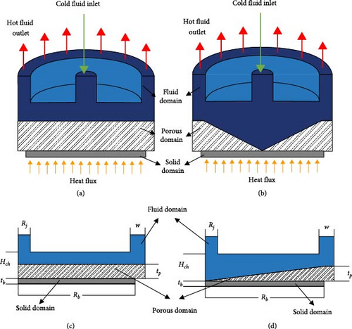
| Parameter | Value range | Unit |
|---|---|---|
| Rj | 1.5 | mm |
| Rb | 15 | mm |
| w | 3 | mm |
| Hch | 3 | mm |
| tb | 1 | mm |
| HR = tP/Hch | 0, 0.25, 0.5 | — |
2.2. Governing Equations
The energy balance and momentum equations in the flow/porous domains and the energy balance equation in the solid domain were solved to understand the thermohydraulic performance of jet-to-porous heat sinks. A turbulent model was used to simulate the flow behavior in the flow domain [20, 21]. Also, the laminar fluid flow and local thermal equilibrium were used for the porous domain [22, 23]. The Darcy–Brinkman–Forchheimer equations were solved for the porous domain.
- (i)
Steady-state heat transfer and fluid flow.
- (ii)
No-slip boundary condition.
- (iii)
Negligible heat radiation, viscous dissipation, gravitational forces, natural convection, and other body forces.
- (iv)
Newtonian and incompressible fluid flow.
- (v)
The porous medium was considered to be isotropic, nondeformable, homogeneous, and saturated.
| Parameter | Value range | Unit |
|---|---|---|
| ∅ | 0.9 | — |
| PPI | 60 | — |
| K | 2.066 × 10⁻⁹ | m2 |
| F | 0.077 | — |
| kf | 0.6 | W/m·K |
| ks | 205 | W/m·K |
| keff | 9.01 | W/m·K |
2.3. Numerical Method and Data Reduction
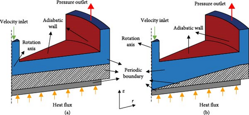
Ansys Fluent was employed to model the jet heat sink. Applying the Semi Implicit Method for Pressure Linked Equation (SIMPLE) technique, pressure, and velocity variables was coupled. A pressure-based solver and the second-order upwind differencing approach were utilized for the momentum and energy balance equations. To reduce the computational cost, a 22.5° slice of the geometry was simulated, and the rotational periodic boundary condition was set as shown in Figures 2(a) and 2(b). A uniform temperature and velocity profiles were considered for the inlet with a turbulence intensity of 5% and turbulence viscosity ratio of 10. Also, constant pressure and heat flux were considered for the outlet and the base boundary conditions, respectively. All other walls were adiabatic. Wall boundary conditions and computational domains are presented in Figures 2(a) and 2(b). A list of boundary conditions is presented as follows:
-
Inlet: u = uin, T = Tin = 25°C.
-
Outlet: P = Pout = 0.
-
Fluid–solid interface: u = 0, Tf = Ts, and .
-
Base wall: .
2.4. Grid Independence Study and Validation
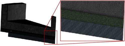
A sample of the generated mesh for HR = 0.25 is demonstrated in Figure 3(a). As seen, the grid is dense in the porous and fluid interface due to higher gradients. A grid independence study was conducted using four different grid sizes, ranging from 2 to 9.5 million elements. The study evaluated the thermal resistance of the jet heat sink with a CPH layer at HR = 0.5 and Re = 25,000, as seen in Figure 3(b). The results showed that there was less than a 3% difference in the thermal resistance of heat sinks with 6.5 and 9 million mesh sizes. As a result, the grid with 6.5 million elements was chosen for further simulations.

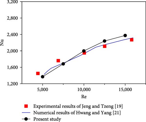
The numerical model of the jet-to-porous heat sink was validated using experimental results from Jeng and Tzeng [19] and numerical results from Hwang and Yang [21]. They studied slot jet-to-porous heat sinks with different height ratios. The Nu number versus Re number is plotted in Figure 4 for a height ratio of 0.5 to validate the numerical method. As evident, the results indicate an acceptable agreement between the experimental results (max error of 4.5%) and numerical data (max error of 3%).
3. Results and Discussions
The present study examined the performance of jet impingement heat sinks with constant and variable porous height layers. The coolant Re number varies from 5,000 to 25,000. The study utilized streamlines and velocity/temperature profiles/contours to identify important flow and heat transfer features of jet-to-porous heat sinks.
3.1. Constant Porous Height
Figure 5 shows the velocity contours and streamlines of two jet impingement heat sinks with constant porous height (CPH) layers and a plain surface at Re = 5,000 on the r–z midplane. In the jet heat sink with a plain surface, the liquid jet first impinges the bottom plain surface and then flows radially which results in the formation of a large recirculation area. As expected, the liquid velocity decreases in the radial direction as the cross-sectional flow area increases. In the jet heat sink with a CPH layer, the porous layer deteriorates the incoming flow momentum, resulting in a smaller recirculation area. This is because the porous media induces a higher flow resistance reducing the jet momentum. Also, as the porous height ratio (HR) of the CPH layer increases from 0.25 to 0.5, the jet momentum losses become greater, thereby further reducing the flow velocity and shrinking the flow recirculation zone.
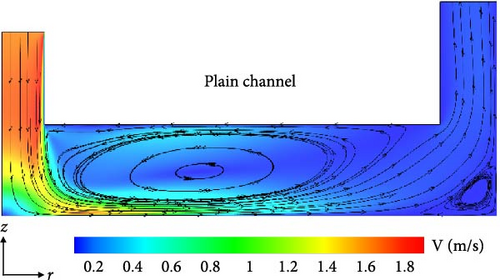
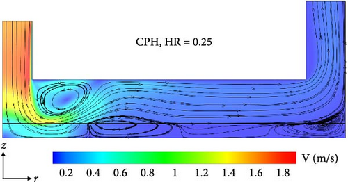
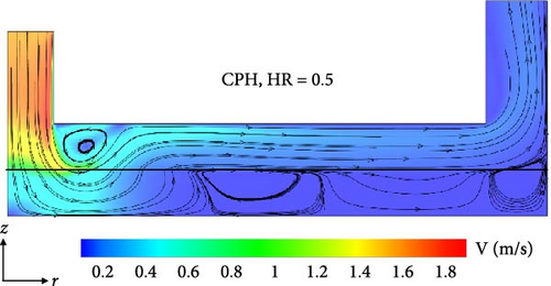
Figure 6 shows the radial base temperature of the heat sinks with a plain and two CPH layers at Re = 5,000 and 25,000. The minimum temperature is observed at the stagnation point, where the thermal boundary layer is the thinnest as the jet impinges the plain/porous surfaces. The surface temperature then gradually increases in the radial direction due to a drop in the flow velocity and the thermal boundary layer growth. Figure 6(a) demonstrates that, at a low Re number of 5,000, the use of a CPH jet layer reduces the base temperature, regardless of the porous height. This is attributed to the increased heat transfer area, fluid mixing, and effective thermal conductivity in the porous domain. Figure 6(b) shows that, at a higher Re number of 25,000, the thermal performance of the CPH jet heat sinks deteriorates compared with that of the plain channel. The Darcy–Brinkman–Forchheimer equation states that and are viscous and drag force terms in the porous domain, respectively. At high Re numbers, the nonlinear drag term is dominant [29]. In other words, the low thermal performance of CPH jet heat sinks compared with the plain jet surface is attributed to significant jet momentum losses at high jet Re numbers, which outweigh the positive effects of employing porous domain. It should be highlighted that the CPH heat sink with a shorter height ratio of 0.25 outperforms the jet-to-porous heat sink with a HR = 0.5 at Re = 5,000 and Re = 25,000. The increase in porous height leads to an increase in effective thermal conductivity. Conversely, thicker porous films result in larger jet momentum losses. The detrimental consequences of jet momentum loss surpass the benefits of increase in effective thermal conductivity, resulting in a decrease in the thermal performance of the porous layer at HRs.
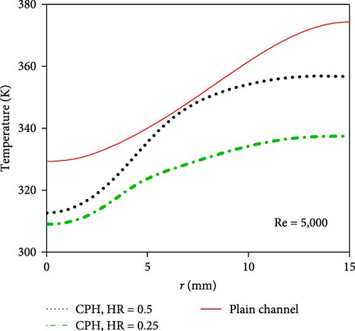
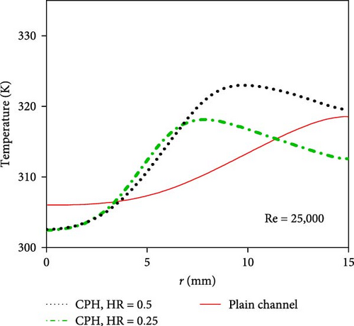
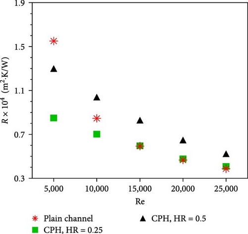
Figure 7(a) shows the pressure drop penalty of jet impingement heat sinks employing a plain and two constant porous height layers at various Re numbers. As expected, the pressure drop penalty increases with the Re number due to augmented frictional losses at high flow rates. At a given Re number, a CPH jet heat sink exhibits a higher pressure drop penalty than the plain jet surface due to the high flow resistance of the porous domain. Also, the pressure drop penalty of the porous jet surface decreases as the thickness of the porous layer decreases. Figure 7(b) shows that the thermal resistance of a jet impingement heat sink decreases with Re numbers due to a thin thermal boundary layer and augmented flow mixing at higher flow rates. At low Re numbers (e.g., 5,000), the thermal resistance of a CPH jet heat sink is lower than that of the plain surface due to the enhanced heat transfer surface area, flow mixing, and effective thermal conductivity offered by the porous layer. At high Re numbers, the jet heat sink with the plain surface shows a lower thermal resistance owing to the high jet momentum losses associated with the porous layer at high flow rates. More importantly, the thermal resistance of the jet impingement heat sink with a thinner porous layer is lower than that of the heat sink with a thicker porous layer. This is because the negative effects of jet momentum losses in thicker porous layers outperform the thermal enhancements of higher thermal conductivity and fluid mixing. In conclusion, the thermal resistance of the CPH channels of HR = 0.25 and HR = 0.5 is 5.5% and 35% higher than the plain channel at Re = 25,000, respectively. However, the thermal resistance of HR = 0.25 and HR = 0.5 is 45% and 16% lower than plain channel at Re = 5,000, respectively.

3.2. Variable Porous Height
As discussed in the previous section, employing a porous layer in an annular jet heat sink increases the pressure drop penalty and decreases the thermal performance at high flow rates. In this section, jet impingement heat sinks employing a variable porous height (VPH) layer are studied to examine whether a VPH jet heat sink can overcome the drawbacks of a CPH jet heat sink.
Figure 8 shows the velocity contours and streamlines of jet impingement heat sinks with a CPH and a VPH layer at HR = 0.5 on the r–z midplane. As evident, the jet heat sink with a variable porous height layer offers a higher radial flow velocity (particularly close to the jet center) than the jet heat sink with a constant porous height layer. As such, the jet momentum losses are less in the VPH jet heat sink.
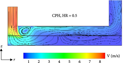
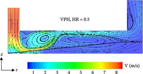
Figure 9 shows radial base temperatures of heat sinks with plain, CPH, and VPH layers at Re = 5,000 and 25,000. As shown in Figure 9(a), at low Re numbers (e.g., 5,000), the base temperature of the VPH heat sink is less than that of the plain surface due to the increased heat transfer area, flow mixing, and effective thermal conductivity in the VPH jet heat sink. Also, the thermal performance of the VPH jet heat sink is better than that of the CPH jet heat sink. This is because the jet momentum losses are less in the VPH jet heat sinks compared with the CPH jet heat sinks. At high Re numbers (e.g., 25,000 in Figure 9(b)), the thermal performance of the VPH jet heat sinks is better than the CPH jet heat sinks due to the reduced jet momentum losses offered by the variable height profile of the VPH heat sink.
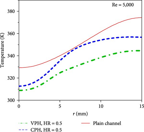
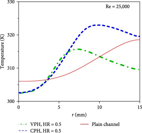
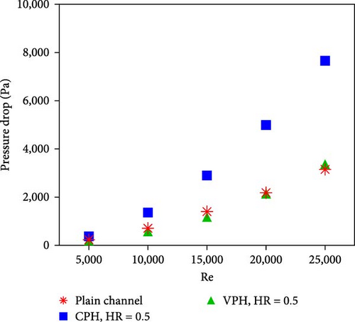
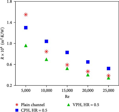
Figure 10(a) shows the pressure drop penalty of jet impingement heat sinks with plain, CPH, and VPH layers at different Re numbers. As shown, the pressure drop penalty of the VPH jet heat sink is significantly lower than that of the CPH jet heat sink and is almost identical to that of the plain heat sink. This is because the jet momentum losses and associated flow resistances are significantly reduced in the VPH jet heat sinks compared with the CPH jet heat sinks. Figure 10(b) shows the thermal resistance of jet heat sinks with plain, CPH, and VPH surfaces at different Re numbers. As evident, the thermal resistance of the VPH jet heat sink is lower than that of the CPH jet heat sink and the plain jet heat sink. This is attributed to (a) the low jet momentum losses of the VPH heat sink compared with the CPH heat sink, (b) the high thermal conductivity associated with the thin porous layer of the VPH jet heat sink compared with the plain channel, and (c) enhanced surface area and flow mixing allowing an effective jet–porous interaction.
3.3. Overall Performance
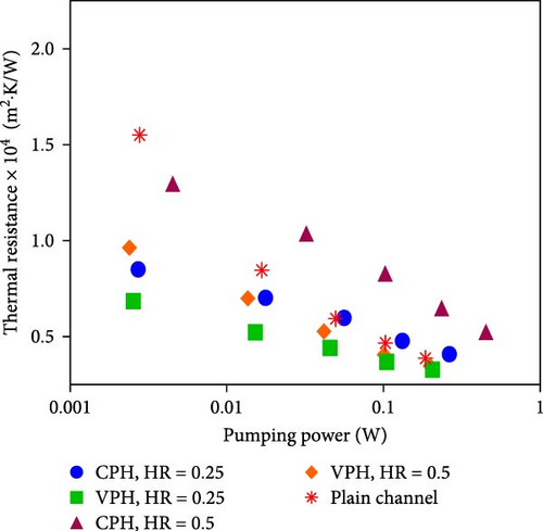
Figure 11 shows the thermal resistance of all the cases as a function of the pumping power. Considering thermal and hydraulic performance, this comparison demonstrates which case requires less pumping power to reach the specific thermal resistance. As seen, the thermal resistance of the VPH heat sink with HR = 0.25 is minimal at a constant pumping power. On the other hand, the CPH heat sink with HR = 0.5 has the maximum value of thermal resistance at all the pumping power, except the lower pumping powers which plain heat sink is the worst case. Figure 11 shows employing higher porous thickness in the channel induces higher momentum loss and decreases thermal performance as discussed in the previous sessions. Also, it shows that using the VPH channel enhances the heat sink performance compared to the CPH and plain channels.
4. Conclusions
- (i)
At low Re numbers (e.g., 5,000), the jet heat sink with a CPH layer has a better thermal performance than the plain jet heat sinks due to the enhanced surface area and flow mixing offered by the porous layer. At high Re numbers (e.g., 25,000), the thermal performance of the plain channel exceeds that of the CPH layer due to the high jet momentum losses associated with the porous layer at high flow rates. The thermal resistance for HR = 0.25 and HR = 0.5 is 45% and 16% lower than the plain channel, respectively.
- (ii)
The thermal performance of the jet impingement heat sink with a thinner porous layer is higher than that of the jet heat sink with a thicker porous layer. The results showed that the thermal resistance of the CPH channels for HR = 0.25 and HR = 0.5 is 5.5% and 35% higher than the plain channel at Re = 25,000, respectively.
- (iii)
The pressure drops in the VPH jet heat sinks are significantly lower than that of the CPH jet heat sink and are almost identical to that of the plain jet heat sink in the flow rate range examined. For instance, the pressure drop for the CPH channel is up to 44% higher than the VPH heat sink at HR = 0.5 and Re = 25,000.
- (iv)
The thermal performance of the jet heat sinks employing variable porous height layers is higher than that of the CPH and plain jet heat sinks due to (a) the low jet momentum losses, (b) the high thermal conductivity, and (c) the enhanced surface area and flow mixing associated with the thin porous layer of the VPH jet heat sink. It can be seen that the thermal resistance of a variable porous height layer is 9.63 × 10⁻⁵ (m2·K/W), which is 25% and 37% lower than that of the constant porous height surface with HR = 0.5 and plain surface at Re = 5,000, respectively.
In summary, the present study demonstrates that jet impingement heat sinks employing a variable porous height layer are promising thermal management solutions for future electronic systems.
Nomenclature
-
- D:
-
- Diameter (mm)
-
- F:
-
- Dimensionless Forchheimer coefficient
-
- h:
-
- Heat transfer coefficient (W·m−2·K−1)
-
- H:
-
- Height (mm)
-
- HR:
-
- Height ratio
-
- KE:
-
- Turbulent kinetic energy
-
- k:
-
- Thermal conductivity (W·m−1.K−1)
-
- K:
-
- Permeability (m2)
-
- L:
-
- Length (mm)
-
- Nu:
-
- Nusselt number
-
- ΔP:
-
- Pressure drop (Pa)
-
- q″:
-
- Heat flux (W·m−2)
-
- r:
-
- Radial direction
-
- R:
-
- Radius (mm)
-
- Re:
-
- Reynolds number
-
- t:
-
- Thickness (mm)
-
- T:
-
- Temperature (°C)
-
- ΔT:
-
- Temperature difference (°C)
-
- U:
-
- Velocity (m/s)
-
- w:
-
- Outlet width (mm)
-
- Z:
-
- Axial coordination.
Greek
-
- ε:
-
- Turbulence dissipation rate
-
- ρ:
-
- Density (kg·m−3)
-
- µ:
-
- Dynamic viscosity (kg·m−1·s−1)
-
- ϑ:
-
- Kinematic viscosity (m2·s−1)
-
- ∅:
-
- Porosity.
Subscripts
-
- ave:
-
- Averaged on surface
-
- b:
-
- Solid base
-
- ch:
-
- Channel
-
- e:
-
- Kinetic energy
-
- f:
-
- Fluid
-
- J:
-
- Inlet jet
-
- r:
-
- Related to radial direction
-
- s:
-
- Solid
-
- w:
-
- Related to wall
-
- z:
-
- Related to axial direction
-
- 0:
-
- Base simulations for plain heat sink.
Conflicts of Interest
The authors declared that there is no conflicts of interest.
Acknowledgments
Mohsen Mashhadi Keshtiban, Mohammad Zabetian Targhi, and Mohammad Mahdi Heyhat greatly acknowledge Iran National Science Foundation (INSF) for the financial support of this work (project no.4005020).
Open Research
Data Availability
No underlying data were collected or produced in this study.


