A Space Vector–Based Long-Range AOA Localization Algorithm With Reference Points
Abstract
In long-range missions based on angle-of-arrival positioning, the angle measurement error of unmanned aerial vehicles is a major source of error. Therefore, reducing the unmanned aerial vehicle angle measurement error is crucial to achieve accurate remote positioning. In this paper, we propose a space vector–based method to correct the space vector of the target for the unmanned aerial vehicles when there are fewer than three available reference points, which in turn corrects the angular value of the target relative to the unmanned aerial vehicles. Simulation results show that when the distance between the reference point and the unmanned aerial vehicles is smaller than the distance between the target and the unmanned aerial vehicles, the azimuth measurement error can be reduced to 55% of the original error for the case of a single reference point, while the pitch angle measurement error remains almost unchanged. In the case of more than two reference points, the azimuth measurement error can be reduced to 1e5 and the pitch angle measurement error can be reduced to 30% of the original error. This method can be adapted to the rapid positioning task for high-speed and high-mobility targets without iteration, low computation, good correction effect, and the need of prior known data set reference.
1. Introduction
Target localization is a critical task in engineering, which requires the utmost attention. Although much research has been conducted on the localization of low-speed targets at a close range, the flight speed of aircraft increases rapidly due to technological advancements. Consequently, there is an increasing demand for long-range localization of high-speed moving objects, making it a critical area of concern. High-speed motion inevitably results in long-distance measurement and positioning. Under long-distance conditions, as the speed of the vehicle increases and the distance between the unmanned aerial vehicle (UAV) and the target can reach up to about 100 km, even a minor angular measurement error can result in a substantial positioning error. For instance, an angular measurement accuracy of 0.1° for a moving target can lead to positioning errors on the order of kilometers in such scenarios. Consequently, reducing angular measurement errors holds great significance for enhancing long-distance positioning and tracking accuracy.
The utilization of optoelectronic pods has gained widespread popularity, accompanied by an escalating demand for heightened accuracy [1]. These optical platforms are typically equipped with detectors or imaging sensors that can be precisely oriented to designated positions in response to input commands. This capability allows for continuous positioning and tracking of specific targets. To illustrate the problem of target positioning and tracking, UAVs are considered as innovative intelligent sensor platforms. The basic principle behind their positioning involves obtaining angle and distance information regarding the target relative to the UAV through optoelectronic pods. Commonly used positioning methods include received signal strength (RSS) [2], time of arrival (TOA) [3], time difference of arrival (TDOA) [4], and angle of arrival (AOA) [5]. Among the positioning methods, AOA-based positioning methods do not require precise time synchronisation and are easier to implement and more accurate than other methods. Because of this, it has become a popular tool for target localization and is the preferred choice for long-range localization challenges.
Among the AOA location problem, in order to achieve a more precise target localization, literature [6] and literature [7] proposed an overall least squares positioning method based on different measurements, and this method can achieve zero deviation of the mean value of the positioning result in the case of small measurement noise, and at the same time, it can be verified through mathematical calculations and simulation analyses that the statistical law of the final positioning error is close to the lower boundary of the Claramello Lower Bound (CRLB). However, since the noise component of the observation matrix constructed by the overall least squares algorithm is not precise enough, the use of this algorithm will lead to a sharp decrease in the performance of the algorithm when the measurement error is large. Literature [5] proposed a constrained overall least squares algorithm based on the overall least squares algorithm, which fully considered the distribution structure of the error in the observation matrix, so that the final localization results achieved high localization accuracy. Subsequently, literature [8] applied the constrained overall least squares algorithm to the AOA localization algorithm and achieved better results, and literature [9] extended the application of this algorithm to the localization scenarios of wireless sensor networks, which further enlarged the application scope of the constrained overall least squares algorithm. However, the algorithm of constrained overall least squares requires Newtonian iteration in the computation process, and the iterative computation will inevitably lead to the defect of higher computational complexity, which is not conducive to the application of the constrained overall least squares algorithm in online positioning tasks. Literature [10], on the other hand, improves the constrained overall least squares algorithm with regularisation, which further reduces the positioning error.
Obviously, the highest accuracy for AOA positioning is the CRLB, but it is the number of UAVs and the measurement accuracy of the sensors that determines the CRLB at long range. Increasing the number of UAVs will obviously lead to higher costs, and when the number of UAVs is high, further increasing the number of UAVs will have less impact on the final positioning results. Therefore, in order to get more accurate long-distance target localization results, the most important thing is the correction and compensation of the angular measurement error.
From the sensor itself, to improve the manufacturing of angular measurement accuracy is an extremely common idea [11], but it is clear that the sensor accuracy and angular accuracy to a certain degree and the relevant costs tend to increase significantly [12]. One of the most commonly used should belong to the given reference method [13], that is, the use of high-precision instruments on the installation error testing, adjustment, and retesting, until the error to meet the use of requirements; it is obvious that the implementation of this method is extremely complex and costly, and when the sensor is used for a period of time, it often needs to be adjusted again, undoubtedly adding a greater workload.
Also, in literature [14], in order to reduce the problem of angle-of-arrival fluctuations, a coronal non-Kolmogorov turbulence spectral model is developed, and an analytical expression for the angle-of-arrival fluctuations of light waves propagating in the coronal environment is derived. And the combined effects of the non-Kolmogorov spectral index, turbulence outer scale, wavelength, and antenna radius are evaluated. In literature [15], in order to reduce the negative impact of fading channels on the performance of the UAV-assisted dual-hop FSO system, a unified system performance analysis of the UAV-assisted dual-hop FSO/FSO system using the amplify-and-forward relay protocol and the intensity modulation/direct detection technique has been carried out, and the tight closed-form expressions for the outage probability and the average bit error rate of the dual-hop system have been derived, as well as the system’s diversity order in the high signal-to-noise-ratio range of diversity orders. The effects of various system and channel parameters related to attenuation loss, atmospheric turbulence, pointing error impairments, and AOA fluctuations on the system performance are also investigated, and good measurement results can be obtained. These two methods can be used as part of angular error correction, but there is potential for continued development of angular error correction algorithms.
Therefore, analysing and compensating the sensor’s goniometric errors by means of algorithms is becoming an increasingly widespread option. Goniometric error is divided into two parts: deterministic error and random error. Compensation algorithms for deterministic errors are more mature. For example, literature [16] analysed the generation mechanism and error distribution law of the goniometric error caused by improper installation of grating, and by analysing the error distribution law of the calibrated rotary table, the third-order sinusoidal fitting method was used to correct the error of the rotary table, and very good results were obtained. Literature [17] from the angle of spoke flux and Moore’s stripe detailed derivation and analysis of the end face grating axial system error and column grating axial system error and established the error model. Subsequently, in terms of error compensation, literature [18] established the harmonic fitting function and the angle measurement error compensation model of angle measurement of angle grating, designed the signal conversion circuit with differential chip as the core, and developed the embedded software of error compensation module. Zhong et al. [19] employ temperature sensors and intelligent software to compensate for accelerometer drift characteristics. Liu et al. [20] introduce a novel approach for compensating forward velocity errors to address trajectory bias compensation in high-resolution automotive synthetic aperture radar (SAR). Valicka et al. [21] propose a method for identifying anomalous damping in high-Q factor resonators to mitigate angular drift issues.
However, the effect of random errors on the final positioning error during the actual task is also not negligible. For random error correction, literature [22] presents a new error compensation method based on an adaptive differential evolutionary algorithm and BP neural network to enhance electronic compass–based heading angle measurements. However, the neural network’s requirement for substantial training data limits its applicability. Literature [23] suggests a dynamic angular measurement compensation method to resolve star sensor image offset issues arising from attitude changes during the measurement process, thereby compensating for angular discrepancies. Nevertheless, in long-range localization and tracking tasks, compensating through image gray scale can be challenging due to smaller target points and increased image disturbances.
In addition to this, there is a rear rendezvous algorithm [24] that is able to correct angle, position, and other information at the same time. When an airborne optoelectronic pod is utilized for angle measurement, it captures image frames over time, allowing for the determination of more than three continuous points. However, this method necessitates at least three reference points with precisely known positions and involves multiple iterations to obtain the final result, thereby limiting its applicability.
It can be seen that in the research process of AOA localization, the suppression of errors is almost mostly targeted at deterministic errors, while the suppression methods for random errors are relatively few, which lead to difficulties in improving the accuracy of target localization. There are also various problems in the study of random error correction, either its error compensation method is difficult to migrate to a narrower scope of application, or its comparison of image gray scale is not applicable to the process of long-distance target positioning. In the process of cooperative positioning, the manipulation of the UAV formation can make the cooperative UAV and the target appear on the image of the mission UAV at the same time and use this reference point to correct the random error in the angle measurement process. However, the number of writing UAVs that can be used as a reference point in the actual mission will not be too large, so the backward intersection algorithm, which must have at least three UAVs to be effective and requires multiple iterations, is clearly not suitable for this scenario.
- 1.
A space vector–based correction method is first adopted, using a partially coordinated UAV as a reference point in a coordinated mission. This method reduces target measurement angle error in long-range AOA location using the geometric angle invariance theorem during space vector rotation. Using one reference point reduces azimuth error by 55%, while two or more can reduce azimuth error to 10e-5 and pitch angle error by 50%.
- 2.
The correction positioning method of the space vector method can correct the direction of the target relative to the UAV when the number of reference points is less than three, which has a wider application in practice.
- 3.
The algorithm described in this paper does not require multiple iterations, which effectively reduces the computation time.
2. Problem Formulation
2.1. Photographic Positioning Model
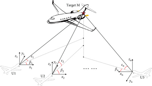
The AOA cooperative positioning task requires more than two UAVs for target positioning, and its positional relationship is shown schematically in Figure 1. Taking UAVs U, U1, and U2 in the mission as an example, the formation is adjusted so that the UAVs of U1 and U2 can appear within the photographic image of U; that is, the UAVs of U1 and U2 are used as the reference points (hereinafter labelled as t1, t2, and collectively referred to as t) to correct the azimuth and pitch angle errors of the target T relative to U obtained from the measurements of U, and the mission scenario is shown in Figure 2. A list of all physical quantities and their letters is in Nomenclature.
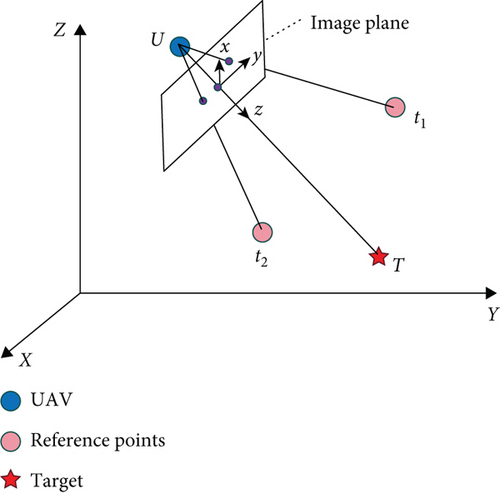
As shown in Figure 2, in the actual task, the target T is made to be located at the center of the sensor image, and the values of its azimuth and pitch angles are obtained by the angle measuring device, while the reference point t is located at the edge position of the image.
The correspondence between the coordinates of the reference point t in 3D space and its coordinates on the 2D image of U follows the colinearity theorem of photographic localization, the principle of which is shown in Figure 3.
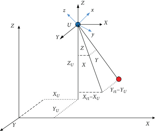
Through Equation (2), it can be seen that the core of the covariance theorem, that is, spatial rotation and the spatial vector formed by a point in three-dimensional space with the position of the sensor, can be rotated and scaled to obtain the coordinates of the two-dimensional point corresponding to the three-dimensional point on the photographic image.
2.2. Angle Error Correction Algorithm
By manipulating the formation of the mission UAVs so that the two UAVs can appear within the photographic image of the main UAV (U), the number of available reference points at this point is two, which are denoted as t1 and t2, respectively. The azimuth and pitch angles of the target with respect to the UAV can be considered the angle between the spatial vector pointing from the UAV to the target and the X and Z axes of the geodetic coordinate system O-XYZ. Since the distance of the target relative to the UAV cannot be obtained from the AOA measurement, the direction vector is taken as a unit vector in the calculation, and its modulus length is one.
According to the theorem of invariant space angle before and after vector rotation in Section 2.1, the following equations can be obtained.
The main task of this paper is to find a more accurate vector .
Since the vector must have a modulo of 1, there is no need to include an additional constraint for this.
During spatial rotation, the projection plane may change, leading to adjustments of azimuth and pitch angle values. However, the spatial angle formed by the two vectors remains constant. Based on this, the following angle correction method is proposed in this paper.
2.3. Problem Solving With Two Reference Points
As discussed in the previous section, to obtain the corrected values of the azimuth and pitch angle, it is necessary to determine the projection of the spatial vector onto the plane defined by XOY and YOZ. The problem can be reformulated as the task of finding a spatial vector .
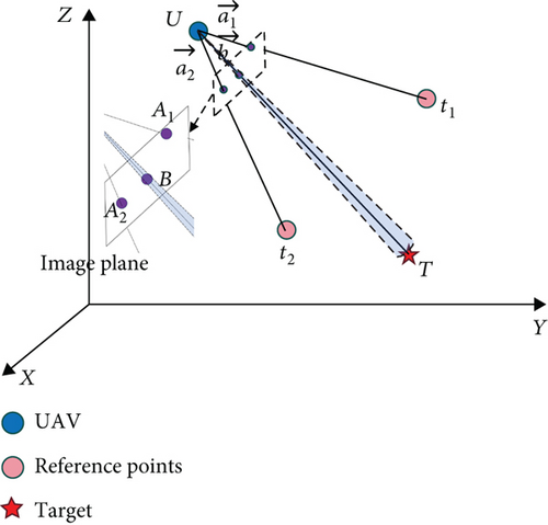
As illustrated in Figure 4, the spatial vector is an unknown three-dimensional quantity.
2.4. Error Analysis of a Case With Two Reference Points
The above equation obtains the result of azimuth and pitch angle correction in the presence of two reference points within the image. In the subsequent AOA positioning calculation, the error of the angle values is required to participate in the calculation; therefore, it is necessary to calculate the error of the corrected azimuth and pitch angle values. From Equations (12) and (13), it can be seen that the values of azimuth and pitch angle are equivalent to the vector X. Therefore, the error analysis of azimuth and pitch angle can be equated to the error analysis of X.
The amount of error in the calculation consists of three parts: the camera internal orientation elements, the UAV self-positioning error, and the pixel extraction error of the image points. Among them, the values of the camera internal orientation elements are all self-contained by the camera outside the field, which can be generally ignored. Therefore, the internal camera orientation element error is not calculated here, and only the pixel extraction error of the image points and the self-positioning error of the UAV are analysed.
where U = (xU, yU, zU), t1 = (xt1, yU1, zt1), and t2 = (xt2, yt2, zt2) denote the coordinate extraction error of the image points of the goniometric UAV U, the two reference points ti, i = 1, 2, respectively. And ΔU1 = (ΔxU1, ΔyU1, ΔzU1), Δt1 = (Δxt1, Δyt1, Δzt1), and Δt2 = (Δxt2, Δyt2, Δzt2) denote the error of the UAV’s self-positioning, both obeying a Gaussian distribution with a mean of 0 and a variance of σu.
where , , and denote the coordinate extraction error of the image points of the main target T, the two reference points ti, i = 1, 2, respectively. And , , and denote the coordinate extraction error of the image point, both obeying a Gaussian distribution with mean 0 and variance σv.
Some of the more detailed derivations are in the Appendices.
2.5. Problem Solving With One Reference Point
However, the actual mission environment is much more complex, and it cannot be guaranteed that the UAV can always capture more than two reference points. Therefore, it is necessary to provide the calculation of vector in cases where only one reference point is available.
The above content has presented using the direction vector approach to calculate the azimuth and pitch angle of the target with respect to the UAV when there are multiple reference points. Since the vector is a three-dimensional unknown, at least three equations are needed for the unique calculation of . However, in cases where one single reference point is available, only two equations can be developed to determine . Hence, an approximate solution is required to address this issue.
By using the coordinates of the target point and reference point in the phase plane, the angle between the spatial vectors of the reference point and target point with respect to the UAV can be determined. In three-dimensional space, vector and the angle between vectors and are known, allowing for the identification of a cone-shaped range of vector whose starting point is at vector and whose vertex angle is 2θ. Meanwhile, with the magnitude of vector set to 1, its range of values is depicted as a circle with a diameter of 1 unit on the conic surface in space, as illustrated in Figure 5.

Since angular measurement errors are small, and the point on the spatial circle that is closest to the spatial vector containing the error is considered the end point of the unit direction vector of the target relative to the UAV. Our objective is to determine a conic plane that begins at the vertex of vector , with a vertex angle of 2θ. Additionally, if the modulus of vector is limited to 1, it will represent the nearest vector to vector on a circle in space with a radius of 1 on the conic surface.
By denoting the end point of vector as point A(xA, yA, zA), the end point of vector as point B(xB, yB, zB), and the end point of vector as point C(xC, yC, zC), the problem can be simplified to locating point B on the circle of space with the minimum modulus for vector .
When vectors , , and lie in the same plane, the magnitude of vector is minimized, and this is proven below.
As the square of any real number is never smaller than zero, the value of is minimized when the absolute value of vector is at its minimum; that is, it equals zero.
When is equal to 0, it indicates that vector can be represented by two vectors and that are coplanar. In this case, vector must also lie within the same plane as vectors and .
When solving the system of equations described above, it is important to note that q is a root of the quadratic equation, indicating that it can take on two different values. The calculation of the quadratic equation is relatively straightforward, and once the corresponding value for p is identified, it is possible to determine the set of two vectors with the smallest angle to vector . Then, these two vectors can be used as the direction vector for the target T. To calculate the azimuth and pitch angle values for T, the same localization method used in the previous section can be applied.
The method proposed in this paper is characterized by its simplicity and low time complexity, which makes it an ideal choice for online positioning requirements.
2.6. Error Analysis of a Case With One Reference Point
in Equation (29) is X in Section 2.3, and X will be used instead of in the calculations that follow during the error analysis.
The expression for E[Δcosθ] is the same as Equation (21). And some of the more detailed derivations are in the Appendices.
3. Simulation and Analysis
The error of the angle calibration results is mainly affected by three main factors: the pixel extraction error, the UAV self-positioning error, and the distance between the UAV and the reference point. Obviously, the smaller the pixel extraction error and the UAV self-positioning error, the smaller the final calibration result error. In the practical application process, when the UAV is determined, its self-positioning error is fixed. And in the case of long-range localization of the target described in this paper, the error of the UAV’s self-positioning is completely negligible. The pixel extraction error depends on the computation method at later times. The distance between the UAV and the reference point has the greatest influence on the calibration results, and it is the easiest to control. Therefore, this paper mainly discusses the influence of the distance between the UAV and the reference point on the calibration results.
3.1. Simulation Conditions
The released reference point proximity to the target is prone to three different states: UT < Ut, UT > Ut, and UT < Ut. Here, the three states are calculated, respectively, to investigate the applicable scope of the calibration method described in this paper.
According to the error analysis in Section 3 and the intercalibration method proposed in this paper, the accuracy of the reference vector is the main cause of the intercalibration results in the case where the target is considered to be at the center of the camera. In the presence of UAV self-positioning errors, the accuracy of the reference vector is mainly related to the distance between the reference point and the UAV.
To verify the applicability and effectiveness of the proposed optimization method, three sets of simulations are carried out. The simulation conditions for each set are summarized in Table 1.
| X -axis | Y -axis | Z -axis | |
|---|---|---|---|
| Position error | 5 m | 5 m | 5 m |
| Angle measurement error | 0.0017 rad | 0.0017 rad | 0.0017 rad |
| Pixel reading error | 0.1 mm | 0.1 mm | 0 mm |
In each set of tasks, two UAVs are used for positioning. The error components of GPS positioning of the UAV in all three directions obey a Gaussian distribution with a mean value of 0 and a mean variance of 5 (unit: m). The angular error combined with the UAV fixation error obeys a Gaussian distribution with a mean value of 0 and a mean variance of 0.0017 rad. The image pixel coordinate reading error obeys a Gaussian distribution with a mean value of 0 and a mean variance of 0.1 (unit: mm) [24]. Besides, structural errors such as mounting errors are compensated.
To verify the usability of the proposed optimization method, the UAVs were divided into three categories based on the varying distances UT and Ut between the mission UAV and the target/reference points.
3.1.1. UT < Ut
Table 2 displays the locations of the mission drones, target points, and reference points. Employing U1 as the reference simulation, the distance between the target and the UAV was 1.9732e3 m, and the distances between the reference point and the UAV were 7.4817e3 and 8.8865e3 m, respectively. In this case, the distance between the reference point and the UAV is significantly smaller than that between the target and the UAV.
| X -axis | Y -axis | Z -axis | |
|---|---|---|---|
| U1 | 1100 m | 6800 m | 90 m |
| U2 | 4300 m | 2500 m | 70 m |
| T | 2100 m | 5100 m | 30 m |
| t1 | 7000 m | 2200 m | 10 m |
| t2 | 9500 m | 3900 m | 70 m |
3.1.2. UT > >Ut and Ut Are Smaller
Table 3 displays the positions of the mission drones, target points, and reference points. UAV U1 was employed as the reference simulation, and the distance between the target and the UAV was 8.0535e3 m, while the distances between the reference point and the UAV were 94 and 43 m, respectively. In this case, the distance between the reference point and the UAV is notably smaller than the distance between the UAV and the target.
| X -axis | Y -axis | Z -axis | |
|---|---|---|---|
| U1 | 2800 m | 8200 m | 100 m |
| U2 | 6300 m | 4600 m | 100 m |
| T | 9900 m | 1200 m | 10 m |
| t1 | 2850 m | 8278 m | 80 m |
| t2 | 2830 m | 8230 m | 90 m |
3.1.3. UT > Ut
This simulation was divided into three groups.
3.1.3.1. Group 1
Table 4 displays the locations of mission drones, target points, and reference points. Using UAV U1 as the reference for the simulation, the distance between the target and the UAV was 7.8518e3 m, while the distances between the reference point and the UAV were 3.1385e3 and 3.3734e3 m, respectively. Notably, the distance between the reference point and the UAV was smaller than the distance between the target and the UAV.
| X -axis | Y -axis | Z -axis | |
|---|---|---|---|
| U1 | −5300 m | 7700 m | 40 m |
| U2 | 1800 m | 3200 m | 30 m |
| T | 2500 m | 8600 m | 50 m |
| t1 | −2000 m | 8400 m | 30 m |
| t2 | −2600 m | 9300 m | 20 m |
3.1.3.2. Group 2
Table 5 displays the locations of mission drones, target points, and reference points. Taking UAV U1 as the reference in the simulation, the distance between the target and the UAV was 9.5838e4 m. Meanwhile, the distances between the reference point and the UAV were 5.0016e3 and 2.0624e3 m, respectively. Notably, the distance between the reference point and the UAV was smaller than the distance between the target and the UAV.
| X -axis | Y -axis | Z -axis | |
|---|---|---|---|
| U1 | 90,500 m | 22,200 m | 200 m |
| U2 | 34,800 m | 27,500 m | 200 m |
| T | 87,800 m | 118,000 m | 180 m |
| t1 | 85,600 m | 21,200 m | 280 m |
| t2 | 89,700 m | 20,300 m | 260 m |
3.1.3.3. Group 3
Table 6 presents the locations of mission drones, target points, and reference points. With UAV U1 as the reference simulation, the distance between the target and the UAV was 1.0012e5 m, while the distances between the reference point and the UAV were 6.3246e3 and 4.4721e3 m, respectively. It is worth noting that the distance between the reference point and the UAV was considerably smaller than the distance between the target and the UAV.
| X -axis | Y -axis | Z -axis | |
|---|---|---|---|
| U1 | −5000 m | 0 m | 100 m |
| U2 | 5000 m | 0 m | 100 m |
| T | 0 m | 10,000 m | 50 m |
| t1 | 1000 m | 2000 m | 90 m |
| t2 | −1000 m | 2000 m | 90 m |
3.2. Comparison of Error Analysis
3.2.1. UT < Ut
Employing U1 as the reference simulation, the distance between the target and the UAV was 1e5 m, and the distances between the reference point and the UAV were 7.4817e5 and 8.8865e5 m, respectively. In this case, the distance between the reference point and the UAV is significantly smaller than that between the target and the UAV.
The comparison of the corrected angle error is shown in Figure 6.
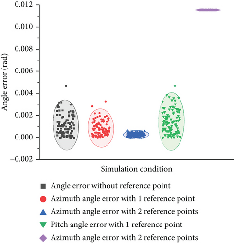
Figure 6 compares the angular errors before and after correction by reference points, where the black dots represent the original angular measurement error with a mean of 0.0014 rad. The red and blue dots represent the correction results of azimuth with one or two reference points, where the mean of the former is 8.4666e-4 rad and the mean of the latter is 2.5884e-4 rad. These results show that the proposed angle correction method can effectively reduce the azimuth measurement error, to 60% of the original error for the single reference point, and reduce the angle error to 20% of the original error for the double reference point. The green and purple dots represent the correction result of the elevation angle with one or two reference points, respectively, where the former is 0.0014 rad and the latter is 0.0115 rad. In the case of a single reference point, the pitch error has almost no effect, while in the case of double reference points, the pitch error is significantly higher than the direct measurement error, which makes the calculation of pitch angle impossible.
It can be seen that in the space vector–based error correction method, one of the main source of error is the extraction of image coordinates. Since the target point is assumed to be at the center of the image with coordinates (0, 0, −f), any reading errors in the pixel coordinates of the reference point can cause calculation errors in the spatial angle, target vector, azimuth, and pitch angles. Specifically, an error of 0.1 mm in pixel extraction can result in incorrect spatial angle calculation. When the reference point is far from the UAV, the pixel extraction error can make the calculation of vector pitch angle entirely unavailable. However, it is still unclear why the pixel extraction error has a more significant effect on azimuth than pitch angle, leading to available azimuth correction values, but entirely out-of-calibration pitch angle correction values. Further investigating this phenomenon is the next logical step.
3.2.2. UT > >Ut and Ut Are Smaller
UAV U was employed as the reference simulation, and the distance between the target and the UAV was 1e5 m, while the distances between the reference point and the UAV were 94 and 43 m, respectively. In this case, the distance between the reference point and the UAV is notably smaller than the distance between the UAV and the target.
The comparison of the corrected angle error is demonstrated in Figure 7.

Figure 7 compares the angular errors before and after correction by the reference point, where the black dots represent the original angular measurement error with a maximum value of 0.0046 rad and a mean value of 0.0014 rad. The red and blue dots represent the result of azimuth correction with one or two reference points, respectively, where the former is 0.0014 rad and the latter is 0.0068 rad. Besides, the green and purple dots represent the correction result of the elevation angle with one or two reference points, respectively, where the former is 0.0014 rad and the latter is 0.02 rad.
The main reason for this situation is that when the reference point is excessively close to the UAV, the error in the self-localization result between the UAV and the reference point has a large impact, which seriously affects the accuracy of the space vectors obtained by coordinate subtraction. The algorithm in this paper is mainly aimed at long-distance positioning, which requires that the influence of the UAV’s own positioning error on the final positioning result is negligible; that is, the space vectors formed by the reference point and the UAV are insensitive to the UAV’s or the reference point’s own positioning error, or else the calibration result will be unavailable. In the algorithm of this paper, the relationship between the distance and the UAV’s self-positioning error is relative; when the self-positioning error is larger, a longer distance is needed to ensure the accuracy of the space vector, while if the error is smaller, only a closer distance is needed to ensure that the results of the angular correction can be used.
3.2.3. UT > Ut
This simulation was divided into three groups.
3.2.3.1. Group 1
Using UAV U1 as the reference for the simulation, the distance between the target and the UAV was 1e5 m, while the distances between the reference point and the UAV were 3.1385e3 and 3.3734e3 m, respectively. Notably, the distance between the reference point and the UAV was smaller than the distance between the target and the UAV.
Figure 8 compares the angular errors before and after correction by the reference point, where the black dots represent the original angular measurement error with a mean of 0.0014 rad. The red and blue dots represent the correction results of azimuth with one or two reference points, respectively, where the mean of the former is 6.6778e-4 rad and the mean of the latter is 8.3339e-5 rad. These results indicate that the proposed angle correction method can effectively reduce the azimuth measurement error. For the single reference point, the angle error can be reduced to about 55% of the original error, and for the double reference points, the angle error can be reduced to below 5% of the original error. The green and purple dots represent the correction results of the elevation angle with one or two reference points, respectively, where the mean of the former is 0.0014 rad and the mean of the latter is 3.4224e-4 rad. It can be seen that the pitch error has little effect in the case of a single reference point, while in the case of double reference points, the pitch error can be reduced to less than 30% of the original measurement error. These results demonstrate the effectiveness of the angle correction method proposed in this study in minimizing angle measurement error.
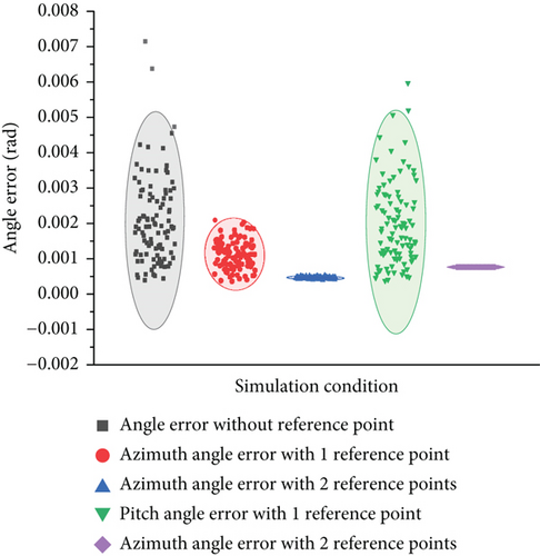
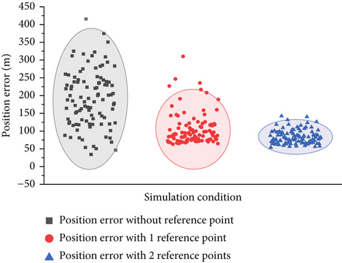
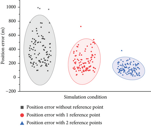
Figure 9 compares the target positioning error before and after reference point correction, where the black dots represent the directly calculated positioning error with a mean value of 183.9 m; the red dots represent the positioning error without single reference point correction, and the mean value is 97.9 m, positioning error reduced to 53.2% of the original error. The blue dots represent the positioning error without using the filter algorithm, and the mean value is 77.6 m, positioning error reduced to 42.2% of the original error. It can be seen that the angle correction method proposed in this study can effectively reduce the final positioning error of the target.
3.2.3.2. Group 2
Taking UAV U1 as the reference in the simulation, the distance between the target and the UAV was 1e5 m. Meanwhile, the distances between the reference point and the UAV were 5.0016e3 and 2.0624e3 m, respectively. Notably, the distance between the reference point and the UAV was smaller than the distance between the target and the UAV.
Figure 10 compares the angular errors before and after correction by the reference point, where the black dots represent the original angular measurement error with a mean of 0.0014 rad. The red and blue dots represent the correction results of azimuth in one or two reference points, respectively, where the mean of the former is 6.2563e-4 rad and the mean of the latter is 4.0957e-4 rad. These results show that the proposed angle correction method can effectively reduce the azimuth measurement error. In the case of a single reference point, the angle error can be reduced to about 55% of the original error, and in the case of double reference points, the angle error can be reduced to less than 30% of the original error. Besides, the green and purple dots represent the correction results of the elevation angle with one or two reference points, respectively, where the mean of the former is 0.0014 rad and the mean of the latter is 9.3666e-4 rad. It can be seen that the pitch angle error has little effect in the case of a single reference point, while in the case of double reference points, the pitch angle error can be reduced to less than 60% of the original measurement error. These results demonstrate the effectiveness of the angle correction method proposed in this study in minimizing angle measurement error.
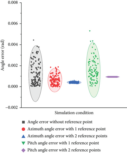
Figure 11 compares the target positioning error before and after the correction of the reference point. The black dots represent the positioning error after the direct calculation, which is 383.5 m; the red dots represent the positioning error in the case of a single reference point, and the mean value is 218.6 m, positioning error reduced to 57.0% of the original error. The blue point dots represent the positioning error without using the filter algorithm, and the mean value is 128.9 m, positioning error reduced to 33.6% of the original error. It can be seen that the angle correction method proposed in this study can effectively reduce the final positioning error of the target.
3.2.3.3. Group 3
With UAV U1 as the reference simulation, the distance between the target and the UAV was 1e5 m, while the distances between the reference point and the UAV were 6.3246e3 and 4.4721e3 m, respectively. It is worth noting that the distance between the reference point and the UAV was considerably smaller than the distance between the target and the UAV.
Figure 12 compares the angular error before and after correction by the reference point, where the black dots represent the original angular measurement error with a mean of 0.0014 rad. The red and blue dots represent the correction results of azimuth with one or two reference points, respectively, where the mean of the former is 7.9369e-4 rad and the mean of the latter is 45302e-5 rad. These results show that the proposed angle correction method can effectively reduce the azimuth measurement error. For the case of a single reference point, the angle error can be reduced to about 55% of the original error, and for the case of double reference points, the angle error can be reduced to below 5% of the original error. Besides, the green and purple dots represent the correction results of the elevation angle with one or two reference points, respectively, where the mean of the former is 0.0014 rad and the latter is 8.11e-4 rad. It can be seen that, in the case of a single reference point, the pitch error is almost not affected, while in the case of double reference points, the pitch error can be reduced to less than 50% of the original measurement error. These results demonstrate the effectiveness of the angle correction method proposed in this study in minimizing angle measurement error.
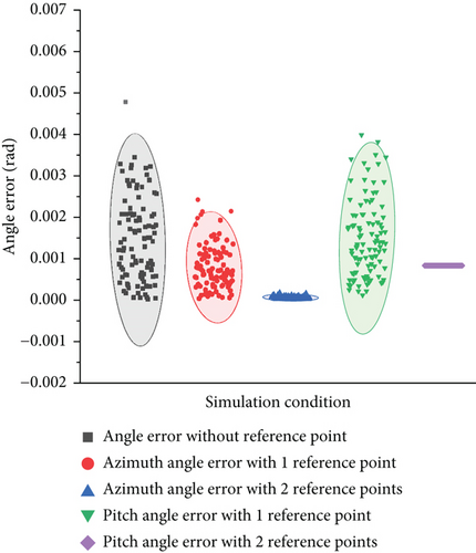
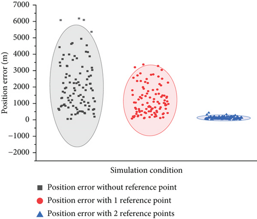
Figure 13 compares the target positioning error before and after the reference point correction. The black dots represent the positioning error when the mean value is 2074.1 m; the red dots represent the positioning error after single reference point correction, and the mean value is 1169.2 m, positioning error reduced to 56.3% of the original error. The blue dots represent the positioning error without using the filter algorithm, and the mean value is 120.4 m, positioning error reduced to 5.9% of the original error. It can be seen that the angle correction method proposed in this study can effectively reduce the final positioning error of the target.
The sources of error affecting the final AOA positioning error can be mainly divided into two parts, one of which is the UAV self-positioning error including GPS error and INS error, which is completely negligible under the long-distance positioning conditions limited in this paper. The main factor affecting the final error of long-distance AOA positioning is the angular measurement error of the sensor; therefore, the algorithm in this paper can greatly improve the final positioning result of the target after application.
It can be seen that under the premise that the distance between the target, the reference point, and the UAV is far enough to make the error of the UAV self-positioning completely negligible; the algorithm in this paper is able to obtain superior angle correction results when UT > Ut, that is, even if the effect of the pixel extraction error is in a controllable range. And the computation is simple, without the need for multiple iterations or data set support, which can play a great role in long-distance high-speed positioning tasks.
4. Conclusion
In this paper, a new method based on space vectors with reference points is proposed to improve the measurement accuracy of azimuth and pitch angles in target positioning. The method connects the target, the reference point, and the UAV into a space vector and applies the theorem of invariance before and after the rotation of the space angle to compensate the random errors of the azimuth and pitch angles. When performing long-distance high-speed positioning calculations, the method is computationally efficient, meets real-time positioning requirements, and significantly reduces positioning errors. When only one reference point is used, the azimuth measurement error can be reduced by 55%. When two or more reference points are used, the azimuth error is reduced to 10-5 and the pitch angle measurement error is reduced by about 50%.
Nomenclature
-
- U:
-
- mission UAV for angular error correction
-
- T:
-
- target
-
- Tt:
-
- reference points served by other collaborative UAVs
-
- (XU, YU, ZU):
-
- spatial coordinates of the UAV U
-
- (Xt, Yt, Zt):
-
- spatial coordinates of the reference point t
-
- (xt, yt, −f):
-
- coordinates of the reference point t in the phase plane
-
- :
-
- the unit vector of the space vector formed by the reference point t and the UAV U
-
- :
-
- the unit vector of the space vector formed by the target point T and the UAV U
-
- :
-
- spatial vectors containing errors between the target T and the UAV U obtained from azimuth and pitch angle measurements
-
- :
-
- the unit vector of the space vector in the phase plane formed by the reference point t and the UAV U
-
- :
-
- the unit vector of the space vector in the phase plane formed by the target T and the UAV U
Conflicts of Interest
The authors declare no conflicts of interest.
Funding
This research was funded by National Natural Science Foundation of China (NSFC) and Natural Science Foundation of Shaanxi Province (grant numbers 61603297 and 2020JQ-219).
Appendix A. Error Calculation Process
A.1. A Case With Two Reference Points
where i = 1, 2.
A.2. A Case With One Reference Point
Open Research
Data Availability Statement
No underlying data was collected or produced in this study.


