Effect of Bluff Body Attributes on Afterburner Combustion Characteristics of a Boron Solid Rocket Scramjet
Abstract
In order to improve the combustion efficiency of boron-containing primary gas in the secondary combustion chamber of a solid rocket scramjet and improve engine performance, the effects of different types of blunt bodies, number of rear blunt bodies, and distance between front and rear blunt bodies on the combustion performance of the secondary combustion chamber were analyzed through numerical calculations. Among the five different blunt bodies, the basic structure has the highest combustion efficiency and total pressure recovery coefficient. When the number of bluff bodies in the secondary combustion chamber is increased from one to three, the boron particle combustion efficiency and total combustion efficiency increase with the growth of the number of bluff bodies, but the total pressure recovery coefficient lessens. When the number of bluff bodies is set as two and the spacing between the front and rear bluff bodies is set equal to 100, 200, and 300 mm, boron particle combustion efficiency and total combustion efficiency increase with the growth of spacing between bluff bodies, but the total pressure recovery coefficient decreased.
1. Introduction
Aspirating hypersonic vehicle has become an important research direction of many countries because of its strong cruising ability, fast flight speed, and difficult interception [1, 2]. The scramjet is the main power unit of the aspirating hypersonic vehicle. According to the fuel type, it can be divided into liquid scramjet and solid scramjet. The solid scramjet ramjet has the advantages of simple structure, low cost, short operational response time, and high energy density. According to the combustion organization mode, solid scramjet ramjet can also be divided into solid rocket scramjet and solid fuel scramjet. Compared with the solid fuel scramjet that pours the fuel into the combustion chamber wall, solid rocket scramjet ramjet has good combustion stability, easy flow regulation, and various mixing modes. A reasonable mixing method can enhance the combustion characteristics of the solid rocket scramjet combustor. At present, the mixing methods mainly include changing the primary gas inlet angle and increasing the cavity and bluff body; the bluff body can provide a high-pressure and low-speed return zone in the central area of the combustor to improve the combustion stability of the combustor and enhance the gas combustion efficiency [3–7].
However, the bluff body structure and its distribution in the afterburner will have an important impact on the combustion performance. Behzadi et al. [8] investigate the effect of bluff body size on the stability boundaries of flashback and blowout and flame shape in premixed natural gas swirl burner. It is found that bluff body size has a significant influence on flashback prevention and to a lesser extent on lean blowout limit while having minor effect on the shape of the flame. The performance of central vortex combustors of three different types of front bluff bodies through experiment performance was studied by Longfei et al. [9]. It was found that the comprehensive performance of a combustor with an annular head bluff body was the best, followed by one with a von Karman curve head bluff body, and the worst was a combustor with a pentahedral front bluff body. Zhaoxu and Qixiang [10] used numerical simulation based on LES method to study the effect of equivalence ratio and inflow Mach number on the performance of afterburner with bluff body. The results show that with the increase of equivalence ratio, the combustion instability frequency has little effect, while the increase of inflow Mach number will increase the combustion instability frequency. Aravind and Kumar [11] numerically simulated the fuel distribution and flow field structure of the cavity/support plate structure ramjet combustor and analyzed the influence of the support plate structure on fuel-air mixing and combustor performance. Compared with the wall injection mode, although the support plate reduced the total pressure recovery coefficient at the combustion chamber outlet by 6.3%, it could evenly distribute the fuel in the whole flow channel and promote the mixing of fuel and air. Mixing and combustion efficiency at the combustion chamber outlet increased by 21.4% and 20.5%, respectively. The combustion flow field of a typical scramjet combustor with a bluff body was simulated by Wei et al. [12], and the effects of fuel injection temperature and pressure on combustor parameter distribution were studied. When the fuel pressure or temperature increased, the ambient pressure and temperature in the secondary combustion chamber changed, the shock wave in the secondary combustion chamber became positive, the hydrogen and oxygen reaction increased, and the reaction area widened. The bluff body structure and its distribution mainly change the flow field structure and thus affect the performance of the combustion chamber. Abdul Majid, Hanapah, and Koten [13] also found that flow aerodynamics determines the flame sustainability in the miniature combustor.
In summary, many scholars have conducted research on the influence of blunt bodies on the combustion characteristics of combustion chambers. But these studies mainly focus on gas and liquid combustion chambers and involve few solid fuels [14–18]. Among many solid fuels, boron has a high enthalpy value. However, due to its long ignition delay time and short particle residence time in supersonic combustion chambers, the combustion characteristic of combustion chambers is poor [19–25]. In reference [26], I have completed research on the influence of some blunt body structure and angle on the combustion characteristics of the afterburner. In this paper, the effects of the structure and number and distance of the blunt body on the combustion performance of the boron-containing solid rocket scramjet will be studied.
2. Models and Numerical Calculation Methods
On the premise that the structure of the secondary combustion chamber and the basic blunt body structure remain unchanged in the article [26], four new blunt body structures were added to study impact on the combustion characteristics of the secondary combustion chamber of a solid rocket scramjet. The five types of blunt body structures are shown in Figure 1, and the triangular blunt body is called the basic blunt body (Case 2), with a blunt body cone angle of 30°. Change the cone angle of the basic blunt body to a round corner with a diameter of 5 mm in Case 1. Add a rear cone angle of 120° at the rear end of the basic blunt body, and make the gas injection direction at a 60° angle with the inlet air in Case 3. For the purpose of reducing pressure drop, change the cone angles at both ends of the blunt body to rounded corners on the basis of Case 3 in Case 4. Change the flat surface of the basic blunt body to an arc-shaped surface in Case 5.
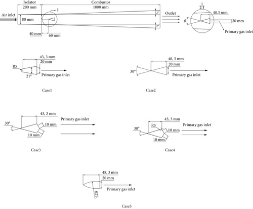
Applying the BSLk-ω turbulence model and the one-step vortex cluster dissipation model, based on King’s boron particle ignition and combustion model, the aerodynamic stripping effect of boron particles in high-speed airflow was considered [26–30], and the Runge–Kutta algorithm was used to iteratively calculate the boron particle ignition and combustion process. In terms of boundary conditions, the Mach number at the isolation section inlet is set as two, and the total temperature is 1160 K. The mass flow of the primary gas is 0.4 kg/s, composed of CO, H2, CO2, H2O, and N2. The boron particle mass flow is 0.2 kg/s, and the initial total temperature of primary gas is 1800 K [26].
3. Results
3.1. Influence of Bluff Body Structure on Afterburner Combustion Characteristics
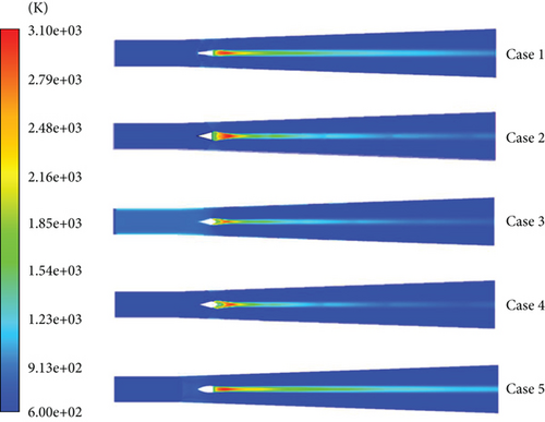
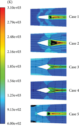
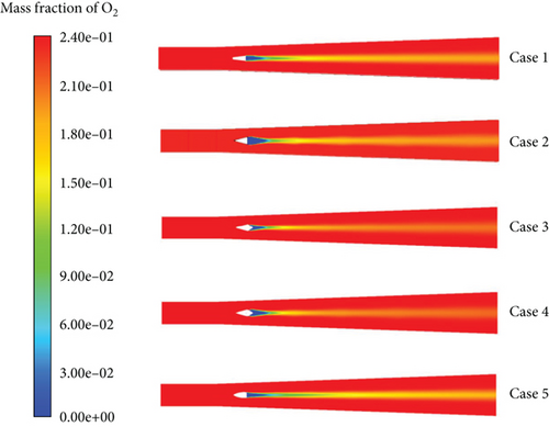
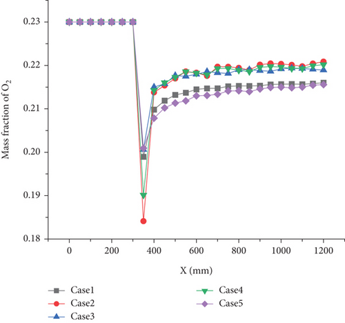
Figures 2, 3, 4, and 5 are the static temperature cloud diagram for each operating condition, the distribution of static temperature streamlines around the blunt body, the O2 mass fraction cloud diagram, and the axial section O2 mass fraction curve, respectively. From the figure, it can be seen that the high-temperature zone in the afterburner is mainly concentrated at the rear end of the blunt body, and a reflux zone is formed at the rear end of the blunt body in Case 1, Case 2, and Case 5. Among them, Case 1 has the widest range of reflux zones, and in Case 3 and Case 4, due to the increase of the rear cone angle of the blunt body, the reflux zone disappears. From the O2 mass fraction cloud map and axial O2 mass fraction curve, it can be seen that in the area from the rear end of the blunt body to the rear end of the afterburner, the oxygen mass fraction of O2 in Cases 2, 3, and 4 is relatively close and significantly higher than the other two operating conditions. However, during the boron particle combustion stage, the oxygen mass fraction content greatly affects the combustion efficiency of the boron particles, and a higher oxygen mass fraction can promote the combustion of the boron particles.
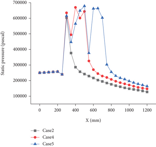
Figures 6 and 7 show the Mach number and static pressure cloud maps for various operating conditions. It can be seen from the figures that shock waves are formed at the leading edge of the blunt body, with Cases 1, 2, and 4 showing oblique shock waves; Case 3 is a positive shock wave, causing blockage at the front end of the blunt body, increasing static pressure, and forming a subsonic region. However, Case 4 changes the cone angles on both sides of the blunt body in Case 3 to rounded corners, transforming the positive shock wave into an oblique shock wave, and the subsonic region disappears. In Case 5, there is a bow shock, which causes the front end of the bluff body to form part of the subsonic region. Under all operating conditions, at the rear end of the blunt body, due to the expansion and acceleration effect of the expansion channel, the fluid velocity is supersonic. The primary gas is sprayed out at the low-speed reflux zone at the back of the blunt body, which can slow down the primary gas speed and increase the particle residence time. Among them, Case 1 has the widest range of low-speed reflux zone.
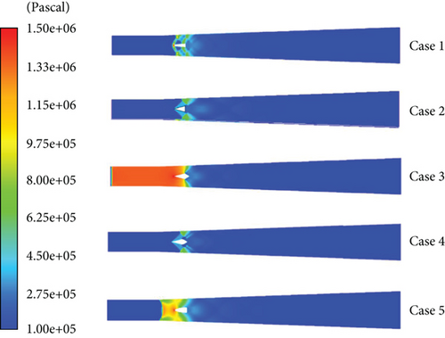
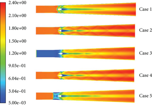
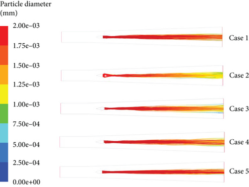
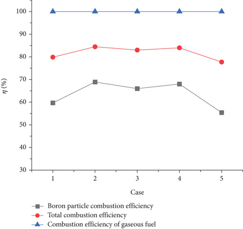
Table 1 shows the total pressure coefficient of restitution under various working conditions. Case 2 can achieve the highest combustion efficiency of boron particles and the minimum total pressure loss. Case 1 produces a bow shock, and the total pressure coefficient of restitution decreases slightly compared with Case 2, resulting in a positive shock, and the total pressure loss of Case 3, which forms the subsonic region, increases significantly. After changing the bilateral cone angles of Case 3 to rounded corners, not only did the subsonic region be eliminated but also the total pressure loss slightly increased. The total pressure loss caused by Case 5 with an arc-shaped cone is the largest among the five operating conditions.
| Case | 1 | 2 | 3 | 4 | 5 |
|---|---|---|---|---|---|
| Total pressure recovery coefficient | 0.648 | 0.662 | 0.6 | 0.616 | 0.57 |
3.2. Bluff Body Number Effects on the Afterburner Combustion Characteristics
Among the three kinds of cone angle bluff bodies studied above, the bluff body with a 30° cone angle obtained the highest boron particle combustion efficiency. Therefore, the bluff body with a 30° cone angle was selected to study the influence of the number of bluff bodies arranged in the secondary combustion chamber on the combustion performance. The bluff bodies are spaced at 200 mm intervals in the axial direction of the secondary combustion chamber. The number of bluff bodies for various cases is shown in Table 2.
| Case | 2 | 6 | 7 |
|---|---|---|---|
| Number of bluff bodies | 1 | 2 | 3 |
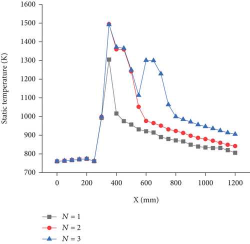
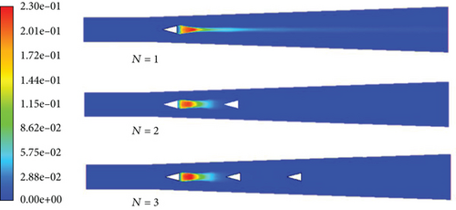
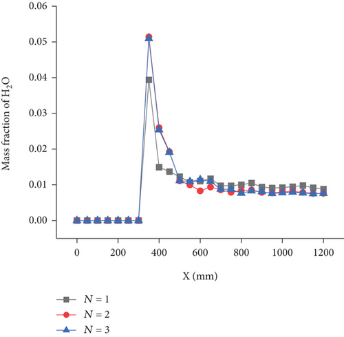
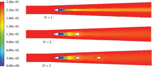
The static temperature cloud diagrams, axial section average static temperature distribution curves, H2O mass fraction cloud diagrams, axial section average H2O mass fraction curves, and O2 mass fraction cloud diagrams under various cases are shown from Figures 10, 11, 12, 13, and 14, respectively. After adding the second bluff body, the high-temperature area in front of the rear bluff body expands, and O2 consumption becomes more uniform. The H2O generation area is basically concentrated between the first and second bluff bodies, and the mass fraction increases, indicating that the gas-phase reaction rate accelerated after adding the second bluff body. After adding the third bluff body, although the static temperature and H2O mass fraction behind the first bluff body have no noticeable change, the O2 consumption rate and H2O generation rate between the second and the third bluff bodies increased. As a combustion supporting agent for boron particles, a higher mass fraction of H2O could accelerate consumption rate of the oxide layer wrapped on the surface of boron particle during its ignition. Therefore, after adding the third bluff body, the oxide layer consumption rate of boron particles is strengthened, particle ignition delay time is reduced, and the boron particle combustion rate is further strengthened.
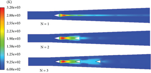
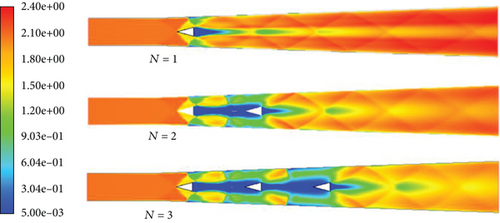
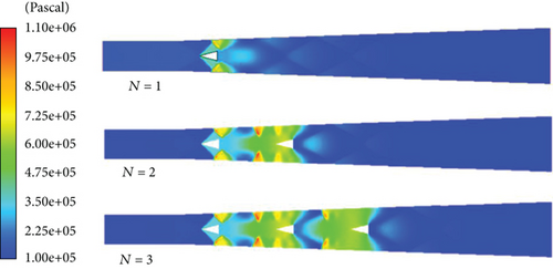
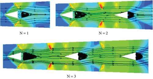
The Mach number cloud diagrams, static pressure cloud diagrams, axial average static pressure distribution curves, and streamline diagrams under various cases are shown from Figures 15, 16, 17, and 18, respectively. After adding the rear bluff body, fluid accelerated in the expansion nozzle but decelerated again under shock wave action, static pressure between bluff bodies noticeably increased, and a subsonic zone appeared in the secondary combustion chamber. Among them, subsonic regions with very small Mach numbers appeared between bluff bodies which are the main primary gas flow regions. With increasing bluff body number, the structure of the recirculation region behind the front bluff body also increases. Due to shock loss, with increasing bluff body number, the Mach number at the secondary combustion chamber outlet decreases significantly, and particle residence time increases.
The particle trajectory marked by particle diameter is shown in Figure 19. With increasing blunt body number, the particle dispersion increases. Figure 20 shows the combustion efficiency of the gas and boron particles and the total combustion efficiency. When the number of bluff bodies is 1, 2, and 3, all gas-phase combustion efficiencies are close to 100%, and the combustion efficiency of boron particles is 68.9%, 77.5%, and 81.5%, respectively. With an increase in the number of bluff bodies, total combustion efficiency and boron particle combustion efficiency increase. These patterns are mainly due to static pressure increase between the two bluff bodies and Mach number decrease, which intensifies the reaction, increases static temperature, accelerates boron particle combustion rate, and prolongs particle residence time.
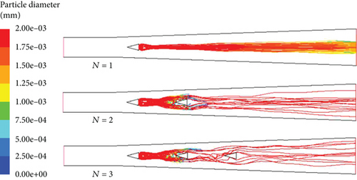
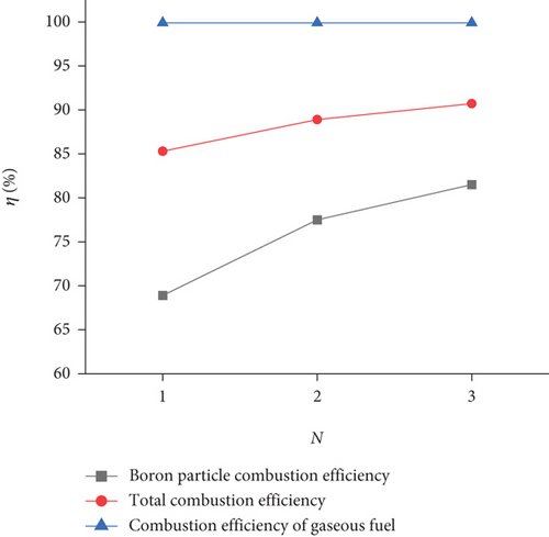
Table 3 shows the total pressure recovery coefficient for various numbers of bluff bodies. The total pressure recovery coefficients for one, two, and three bluff bodies are 0.662, 0.560, and 0.478, respectively. These results reveal that the total pressure recovery coefficient remarkably lessens with increasing the number of bluff bodies.
| Case | 2 | 6 | 7 |
|---|---|---|---|
| Number of bluff bodies (N) | 1 | 2 | 3 |
| Total pressure recovery coefficient (σ) | 0.662 | 0.560 | 0.478 |
3.3. Influence of Bluff Body Distance on the Afterburner Combustion Characteristics
Although the combustion efficiency obtained by three bluff bodies is the largest, its total pressure recovery coefficient is low. Therefore, two numbers of blunt bodies were selected to study the effect of the distance between blunt bodies on combustion performance. The combustion characteristics at the bluff body distance of 100, 200, and 300 mm are compared, and the cases are shown in Table 4.
| Case | 8 | 6 | 9 |
|---|---|---|---|
| Blunt body distance L (mm) | 100 | 200 | 300 |
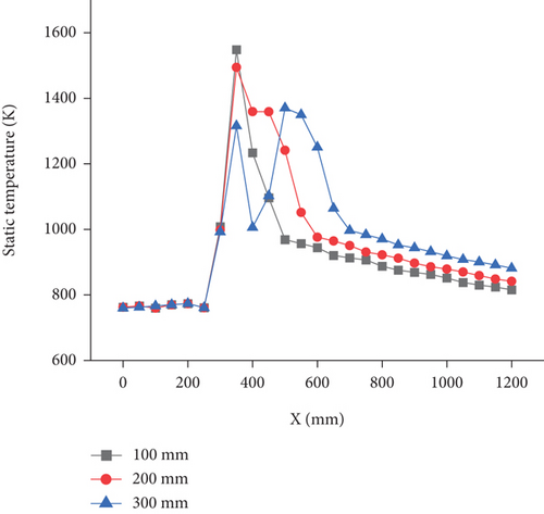
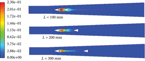
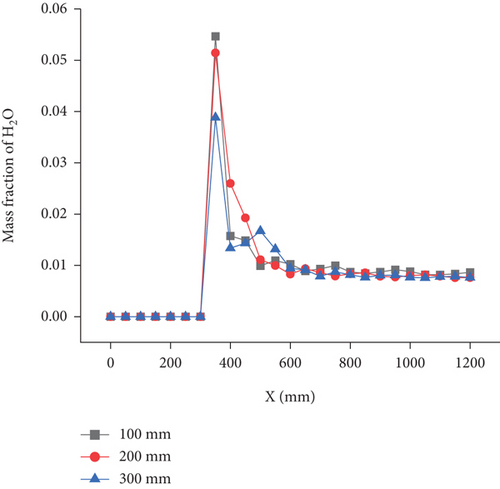
The static temperature cloud diagrams, axial section average static temperature distribution curves, H2O mass fraction, and axial average H2O mass fraction curves for various cases are shown from Figures 21, 22, 23, and 24, respectively. The high-temperature area was mostly located between the front and rear blunt bodies. With the backward movement of the rear blunt body, although the static temperature near the fuel nozzle behind the blunt body decreases, the range of high-temperature area between the front and rear blunt bodies expands. At the rear end of the front bluff body, the H2O generation rate lessens with the bluff body moving backward, and the H2O mass fraction at the front end of the rear bluff body increases.
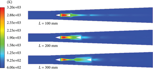
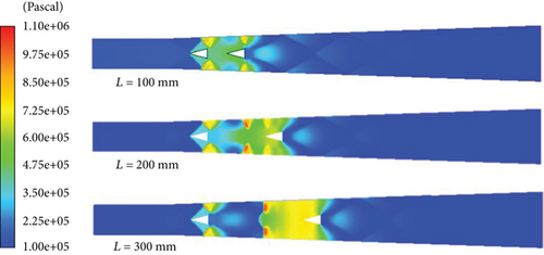
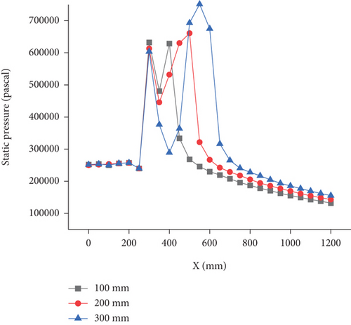
The Mach number cloud diagrams, static pressure cloud diagrams, and axial average static pressure curves for various cases are shown in Figures 25, 26, and 27, respectively. At 100 mm, except for the subsonic area between bluff bodies, other areas in the secondary combustion chamber are basically supersonic. With the backward movement of bluff bodies, shock wave intensity in front of the rear bluff bodies increases, the high pressure and subsonic regions caused by the shock wave also move backward, static pressure increases, the Mach number decreases between bluff bodies, and the Mach number in the secondary combustion chamber also considerably lessens.
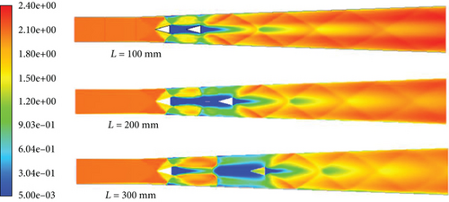
The particle trajectory marked by particle diameter is shown in Figure 28. With increasing blunt body distance, the particle dispersion increases. Figure 29 shows the combustion efficiency of the gas and boron particles and the total combustion efficiency. When the distance between bluff bodies is 100, 200, and 300 mm, all gas-phase combustion efficiencies are close to 100%, and the combustion efficiencies of boron particles in order are 75.5%, 77.5%, and 83%. With the growth of the distance between bluff bodies, the total combustion efficiency and combustion efficiency of boron particles increase.
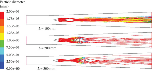
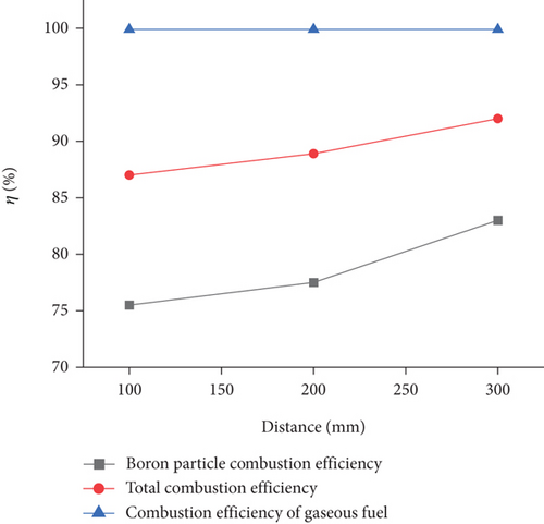
Table 5 shows the total pressure recovery coefficient for three cases of different distances of bluff bodies. The total pressure recovery coefficients for bluff body distances of 100, 200, and 300 mm in order are 0.628, 0.560, and 0.506, which indicates that the total pressure recovery coefficient noticeably reduces with growing the bluff body distance.
| Distance between front and rear blunt bodies (mm) | 100 | 200 | 300 |
|---|---|---|---|
| Total pressure recovery coefficient (σ) | 0.628 | 0.560 | 0.506 |
4. Conclusions
- 1.
Among the blunt body constructions studied, the triangular bluff body is the best at improving primary gas and boron particle combustion efficiency.
- 2.
When the number of bluff bodies is 1, 2, and 3, respectively, the boron particle combustion efficiency and total combustion efficiency increase with the increase of the number of bluff bodies, but the total pressure recovery coefficient is vice versa.
- 3.
When the distance between the front and rear bluff bodies is 100, 200, and 300 mm, respectively, the boron particle combustion efficiency and total combustion efficiency increase with the increase of bluff body distance, but the total pressure recovery coefficient is vice versa.
Conflicts of Interest
The authors declare no conflicts of interest.
Funding
This work was supported by National Natural Science Foundation of China (No. 51666012).
Acknowledgments
This work was supported by National Natural Science Foundation of China (No. 51666012).
Open Research
Data Availability Statement
The ignition combustion model of boron particles has been verified in reference [30] by comparing with the experimental results.


