Tribological Performance of Laser-Based Surface Textured Nonconformal Contacts
Abstract
The benefits of surface textures on rolling and sliding tribological contacts have been an exciting field of study over the last three decades. Laser surface texturing (LST) is a comparatively newer texturing methodology that yields repeatable precise microtextures. A detailed overview of the available literature on the various works in this field is consolidated in this review. The main focus is on the effect of surface textures (with focus on laser ablation) for nonconformal contacts with elastohydrodynamic lubrication (EHL), as in rolling element bearings. A review of literature on textured contacts for the EHL regime, emphasizing its effect on friction, wear, rolling contact fatigue, vibration, texture geometry, and numerical simulation studies, is carried out with possibilities of future works. Basic details on LST processes and various parameters of the laser beam that determine the texture geometry are discussed. Being a field of continuing research, the review paper will aid in understanding the present developments and future directions in laser-based surface texturing for nonconformal tribological contacts.
1. Introduction
Tribology is the study of friction, wear, and lubrication of surfaces in relative motion. Tribological contacts can be categorized as either conformal or nonconformal contacts, depending on the geometry of the surfaces in contact. Conformal contacts, as in journal bearings (rotary motion) and slider bearings (linear motion), have their contact surfaces fit well into each other geometrically so that the apparent area of contact is large with contact pressures lower than 100 MPa (Figure 1a) [1, 2]. In nonconformal (or concentrated) contacts (Figure 1b), the load between the bodies is carried by a relatively small area, resulting in high contact pressures (0.5–4.0 GPa). The dimensions of the contact zone are significantly smaller when compared to the dimensions of the interacting bodies and the radii of curvature of the surfaces in contact [3–6]. Gear teeth, cam and followers, and rolling element bearings having nonconformal surfaces are found in wide spectrum of applications ranging from household kitchen appliances, toys, automobiles, and factory machinery to space applications. It is well-known that in these applications, insufficient lubrication will lead to higher wear and friction [7]. It has been reported that more than 30% of the anomalies reported in rotating systems in different spacecraft missions have found their root cause to be insufficient lubrication at contact points inside the precision ball bearings [8]. On the other hand, an augmented lubricant volume at the contact results in higher viscous frictional losses. Therefore, a continuous effort has been made to enhance the longevity of these contacts with a stable and high energy efficiency operation, by achieving optimized lubrication conditions.
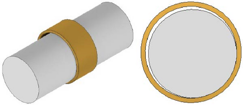
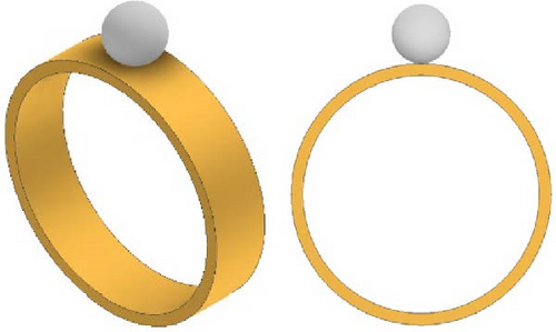
The different approaches employed to improve the life span in these nonconformal contacts are performed by improving the lubricant formulations and additives, applying a surface coating, and creating surface textures on the contacting surfaces. In the present review article, our focus is laid on assessing the parameters that help to achieve enhanced tribological properties in nonconformal tribopairs through surface textures.
1.1. Lubrication Regimes
A typical tribopair operating in lubricated conditions works in one of the three lubrication regimes: (i) boundary, (ii) mixed, and (iii) hydrodynamic (HD) lubrication regimes. These three operating regimes depend on the friction coefficient (COF) and Hersey number (H), where H = µ N/P, function of operating speed (N), lubricant viscosity (µ), and applied load (P). The graphical representation correlating the friction COF and Hersey number for the different lubricating regimes [9] is called the Stribeck curve (Figure 2).
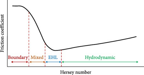
In the hydrodynamic regime, there is no asperity interaction, as the lubricant fully separates the contacting surfaces by its hydrodynamic effect in the converging geometry. The bulk properties of the lubricant play an important role in determining the friction behavior in HD contacts. The friction COF value increases with the increase in Hersey number, which can occur with an increase in operating speed, an increase in the lubricant viscosity, or a reduction in applied load.
In the boundary lubrication regime, the applied load is predominantly supported by the asperities of the contacting surfaces. Here, the majority of the asperities undergo plastic deformation, and plastically deformed asperities result in wear. In this lubrication regime, the friction COF and wear are high, and they prevail when the magnitude of the Hersey number is low. The friction and wear characteristics of contact are determined by the physical and chemical attributes of thin lubricating films generated on surfaces, along with the properties of the bulk material or surface coatings [6].
In a mixed lubrication regime, the applied load is shared by both the asperities of the contacting surfaces and by lubricants. The load on the asperities is shared by both elastically and plastically deformed asperities. As the Hersey number increases, the load shared by the plastically deformed asperities reduces, and the load shared by the elastically deformed surface and lubricant increases, hence resulting in lower wearing of the asperities. Here, a lower quantity of lubricant is available, and hence, the hydrodynamic action does not completely prevail. Elastohydrodynamic lubrication (EHL) is a special case of mixed lubrication regime where the nonconformal contact components like ball bearings and gear teeth shall operate. In EHL, the concentrated contacts generate high contact pressures that significantly increase the viscosity of the lubricant (a piezoviscous behavior) and elastic deformation of the bearing surfaces ensuring a reduced wear of the contacting surfaces and lower friction COF [10]. Due to the prevailing favorable tribological behavior, EHL contacts have always been a topic of keen interest for a tribologist.
Most high-speed precision applications like precision bearings for hard disk drives, dental drills, turbo molecular pumps, precision machinery, spacecraft wheels, and gyroscopes work in the EHL regime of lubrication. The lubrication community has always strived to increase the lifetimes of EHL contacts. Increased lubricant quantity leads to increased friction owing to viscous and churning losses. The aim has been to attain high lifetimes with lower friction and optimal lubricant quantity. Surface texture aids in collecting the lubricant at the contact points and improves the lubricant film thickness with the available lubricant in the contacts, for properly designed texture geometry. Presently, major research in the field of tribology is aimed at combining smart materials (nanolubricants) and smart surface designs (profiling and texturing) of mating solids to reduce friction and wear, thereby enhancing the life of the lubricated concentrated contacts [11]. Surface textures in EHL contacts are comparatively a newer area of research and are dealt with in the present review.
1.2. Surface Textures
The general types of surface textures employed in engineering surfaces are dimples (hemispherical-shaped textures), grooves and cavities (elliptical, triangular, or square-shaped) [12–14] (Figure 3), and more sophisticated multiscale/biomimetic structures. These textures are geometrically characterized by diameter, lateral dimensions, area ratio (percentage of the total textured area over the total surface area), distance between textures (pitch), and aspect ratio (ratio of texture depth to texture diameter) [15] (Figure 4). However, it is worth mentioning that not all surface textures provide beneficial results in all operating conditions, and therefore, selection of the right texture types and their optimum geometry needs to be carried out following the specific requirements and applications [16].
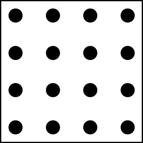
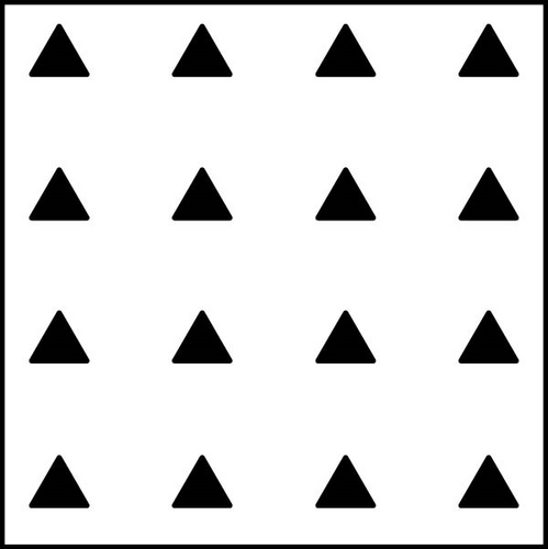
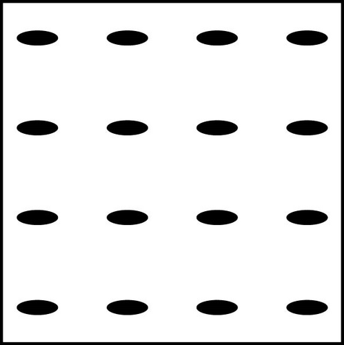
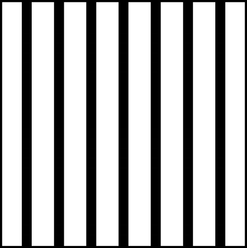
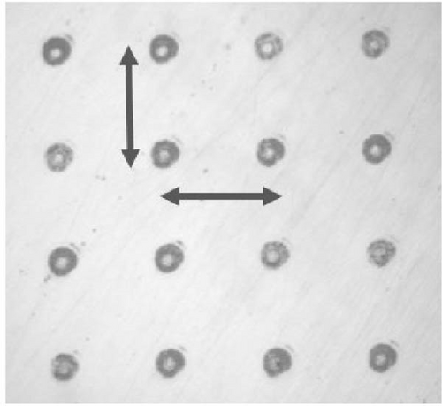
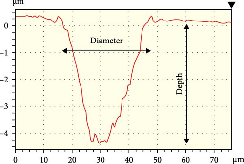
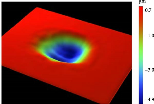
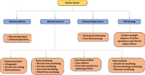
Different types of textures can be achieved by different surface texturing processes (Figure 5) including (a) material addition [17], (b) material removal [18–21], (c) material displacement [22–24], and (d) self-forming methods [17]:
- •
Material addition: The addition of material for creating surface texture is achieved either by chemical or physical deposition processes.
- •
Material removal: The process involves removing material from the substrate surface by creating microholes or grooves. The material removal process is performed by (i) chemical method that includes lithography, reactive ion etching, and electrochemical; (ii) beam machining that includes electron beam machining, ion beam machining, laser beam machining, and pulsed beam machining; (iii) laser beam method that includes laser ablation and direct laser interference patterning; and (iv) other methods that includes abrasive jet machining, electron discharge machining, and ultrasonic machining.
- •
Material displacement: Surface texturing by material displacement is attained by mechanical indentation or LSP approaches. During the material displacement process, the substrate undergoes plastic deformation or redistribution of the substrate from one location to another.
- •
Self-forming methods: In this method, the desired surface texture is obtained through a set of surface operations—for example, initially, a wear-resistant coating is provided on the desired locations on the surface using a mask. Upon running in after removing the mask, the surface locations without the coating are worn out, thereby creating a texture.
A detailed description of different techniques of surface texturing is provided in [17]. The texturing employed in nonconformal contacts is mostly “microtextures” where the dimensions are in the range of micrometers. Laser surface texturing (LST) is the best method to obtain precise and repeatable microtextures, provided the laser beam parameters are aptly optimized. LST is a comparatively newer technology and has obtained wide acceptance, mainly due to the controllability and flexibility of the texturing process by tweaking the laser beam parameters.
In the present review article, we endeavor to discuss the benefits of different surface textures for nonconformal tribological contacts operating in EHL with emphasis on LST. We further discuss achieving the desired surface texture on the contact by LST.
2. Influence of Surface Textures on Tribology of Nonconformal Contacts
2.1. Effect on Friction
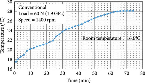
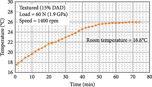
The surface textures on the contacting surfaces influence the surface topography, material microstructure, surface hardness, grain size, and residual stresses, which impact the tribological properties of the contact surfaces [25]. Borghi et al. [26] reported a reduction of friction COF by up to 75% with textured nitriding steel surfaces in starved lubricated pin-on-disk contact conditions. Long et al. [27] also reported a reduction in the friction COF under the starved operating condition for roller thrust bearings. Sudeep, Tandon, and Pandey [28] observed that the reduction in friction COF in the presence of textures is higher in pure sliding cases compared to pure rolling and combined rolling–sliding cases. Friction reduction was associated with a reduction in temperature rise at the textured contacts, owing to effective lubrication, in comparison to polished surfaces (Figure 6). Gauda et al. [29] reported a similar observation of lower temperature rise in microgrooved radial ball bearing compared to conventional bearing, under steady operating conditions. Baharin, Ghazali, and Wahab [30] reported that with DLC coating, a reduction in COF by a factor of two in the textured surface was obtained compared to a smooth surface. During a long displacement reciprocating sliding test under boundary lubrication conditions, Bhaduri et al. [31] found that surface texture was beneficial in reducing the COF, even at lower sliding speeds.
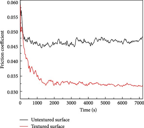
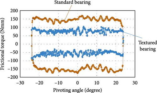
Li et al. [33] performed a ball-on-disk (lapped/dimple textured) configuration (material: GCr15 steel, 60 HRC) at 1.12 GPa contact stress, 0.38 m/s sliding speed, lubricated by graphene suspension and obtained friction reduction of ~35% in case of textured surface (Figure 7). Kelley, Poll, and Pape [34] textured the inner ring of the angular contact ball bearing with elliptical dimples and characterized the frictional torque during the pivoting motion of the bearing at 1.5 GPa contact stress with grease lubrication. They obtained a 50% reduction in frictional torque and reduced wear in the case of textured bearing (Figure 8).
2.2. Effect on Wear
Oksanen et al. [35] reported that surface textures increased the wear life of WS2/tetrahedral amorphous carbon-coated surfaces by more than twice compared to nontextured surfaces at elevated temperatures (250°C). Kumar et al. [36] performed pin-on-disk tests with elliptical dimples at varying area densities in hardened steel and observed that the textured samples exhibited better wear resistance compared to nontextured smooth surface samples. Xu et al. [37], based on reciprocating steel pin-on-textured steel disk tribotests under lubricated conditions, reported that the textured surfaces formed thicker tribofilms resulting in lower wear. Ding et al. [38] also observed better antiwear performance of textured cast iron surfaces in ring-on-ring friction test setup under oil lubrication. Niu et al. [39] reported reduced wear rates for dimpled surfaces compared to a smooth surface on the ball (bearing steel)-on-textured disk (carbon steel) tribotests under starved lubrication. Sun et al. [40] performed laser texturing in the raceways of shaft washers in thrust cylindrical roller bearings and, through bearing level tests in dry conditions, concluded that selected dimple geometry plays a role in determining the wear characteristics.
2.3. Mechanism of Enhanced Tribology by Surface Textures
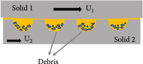
The enhancement of the tribological behavior due to textures is attributed to the prevailing of (a) microhydrodynamic bearings, (b) lubricant reservoir, (c) wear debris trap, and (d) reduced area of contact (Figure 9) [41, 42].
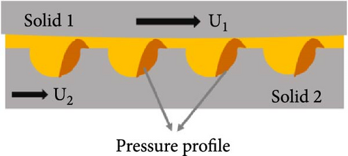
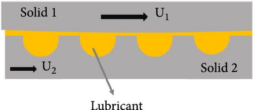
Microhydrodynamic bearing: Each of the microdimples on the surface acts as microhydrodynamic bearings and increases the load-carrying capacity of the lubricant film. The hydrodynamic pressure in the fluid increases in converging regions (near dimple exit) and decreases in diverging regions (near dimple entry). The vapor pressure of the fluid (by cavitation) provides a limitation on the pressure drop at the diverging region so that a “net” pressure increase is achieved with optimized dimple geometry. The piezoviscous behavior of the lubricant in the EHL regime makes the onset of cavitation more likely and aids the microhydrodynamic action [43, 44].
Lubricant reservoir: The microtextures on the surface can act as microreservoirs for lubricant and function as a secondary source or replenishment system of lubricant film at the tribocontacts even in starved lubrication conditions. The presence of the lubricant film increases the film damping at the contact. They can also store solid lubricants (incorporated by burnishing, sputtering, or hot pressing) and provide enhancement of beneficial tribofilms in the boundary lubrication regime of operation [36, 45–48].
Debris trap: Surface textures can trap the wear debris in dry and boundary lubrication regimes and thereby prevent abrasive wear (three body abrasion wear) and related friction instabilities. Microtraps act as a delay mechanism for the wear process, thus improving the wear resistance, fretting fatigue resistance, and life of the components [48–50].
Reduced real area of contact: Surface textures reduce the real area of contact and thus reduce the adhesive friction component and contact stiction. The process followed for texturing can increase the surface hardness near the dimples and increase the wear resistance of the materials [27, 51].
However, enhanced tribological behavior depends on the topology of the textures such as diameter, size (Ezhilmaran, Vasa, and Vijayaraghavan [52] and Mohmad et al. [53]), type of contact (conformal/nonconformal), area density (Ezhilmaran, Vasa, and Vijayaraghavan [52] and Liu et al. [54]), aspect ratio (Ezhilmaran et al. [52]), pattern shape (Yu, Huang, and Wang [12]), and laser pulse duration used for the process (femtosecond to nanosecond) (Zhang et al. [55]). Ezhilmaran, Vasa, and Vijayaraghavan [52] and Mohmad et al. [53] reported a decrease in friction COF with an increase in dimple diameter for different material combinations. Ezhilmaran, Vasa, and Vijayaraghavan [52] reported the influence of dimple area density and aspect ratio on COF during sliding reciprocating tests. Zhang et al. [55] measured the temporal evolution of COF in a linear reciprocating test with oil-lubricated steel ball-on-disk with textured grooves and reported the lowest COF for grooves made with a femtosecond (fs) laser and then picosecond (ps) laser and the highest for grooves made with a nanosecond laser.
Kovalchenko et al. [56] performed pin-on-disk tests and showed the transition of the textured surface toward a lower friction zone in the Stribeck curve when compared to ground and polished samples (Figure 10). They further showed that the dimpled texture expands the range of the lubrication regime and facilitates the transition of lubrication from a high-friction boundary to lower friction mixed regime or even hydrodynamic regime at higher loads and lower speeds [57]. A similar observation was reported by Ding et al. [58], where hardware textured with elliptical dimples increased the range of hydrodynamic lubrication in rotary compressors with enhanced wear resistance while maintaining similar friction values as a smooth surface. The electrical resistance measurement and capacitance measurement at the tribocontacts during experiments provide information on the lubrication regime of operation. Varenberg et al [59]. observed a significant reduction of electrical resistance (up to 69% in steel–steel contact) at the tribocontacts in the presence of surface textures because of the trap of oxide debris into micropores. This could establish the debris trap concept in microdimples, by which microdimples help in reducing the abrasive wear of the contacting surfaces. Gauda et al. [60] measured lesser capacitance across microgrooved radial ball bearings compared to conventional bearing under similar operating conditions, implying increase in lubricant film thickness due to better lubricant retention in textured bearings.
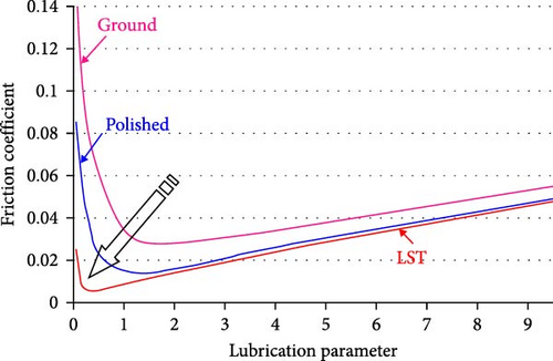
Microdimples reduce adhesive wear due to lower real area of contact, related reduction in asperity contacts, and improved lubricant film formation. The debris trapping (avoids three-body abrasion) and lubricant replenishment properties of the dimples reduce the abrasive wear. This is responsible for the decrease of friction COF compared to the untextured surfaces. LST increases the surface hardness during laser heating (with a reduction of grain size) and reduces the tensile residual stress or enhances the compressive residual stress on the laser-textured surface, which depends on the material and method used [61]. This improves the wear resistance of the textured surface. It may be noted that textured surfaces can also be tailored for high friction applications by providing specific texture patterns, surface hardness, and surface roughness as studied by Dunn [62] and Schille et al. [63] and as discussed by Costa et al. [51] for applications in mechanical transmission systems like clutches and road–tire systems. Although such surfaces showed higher friction, it is interesting to note that their wear was not high, which is mainly attributed to the removal of debris from the contacts (wear debris trapping in the textures).
2.4. Influence of Texture Geometry on Tribology
Suh et al. [64] classified textured geometry as discrete (closed) geometries and continuous (open) geometries. Geometry such as circles, triangles, rectangles, and squares are examples of discrete geometries, whereas patterns such as microgrooves with straight lines or curves with parallel or crosshatch forms are examples of continuous geometries. Special textures like biomimetic or bionic textures [65–69] and laser-induced periodic surface structures (LIPSS) [70] are newer areas of research for improved tribological performance. It is important to study the optimal shape, size, and relative orientation (with respect to sliding/rolling direction) of the surface texture for the required application.
2.4.1. Influence of Texture Depth
Mourier et al. [71] performed optical interferometry measurements of lubricant film thickness on microcavities (generated by a fs pulse laser) passing through an EHL contact. They observed that the microcavity did not have any significant influence on the film thickness distribution under pure rolling conditions. However, for combined rolling–sliding conditions, the microcavity locally increases or decreases the film thickness, depending on the microcavity depth. Under the EHL regime of operation, a local decrease or even collapse of the lubricant layer was observed for deep cavities. In contrast, a significant increase in lubricant film thickness (25%–40% increase) was induced by a shallow microcavity. Shallow microcavities were of the same order of magnitude as the central lubricant film thickness of the smooth contacts. The increase in the local lubricant film thickness in the shallow microcavities aids the transition from boundary lubrication to EHL regime at more severe operating conditions, i.e., lower speeds and higher load conditions. The distance within the Hertzian contact width wherein an increase in the film thickness was observed (Figure 11b, distance in the range of −150 to −50 µm) depended on the slide-to-roll ratio and the time spent by the microcavity inside the contact zone.
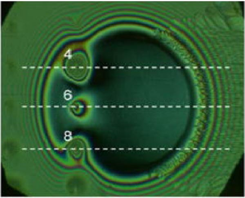
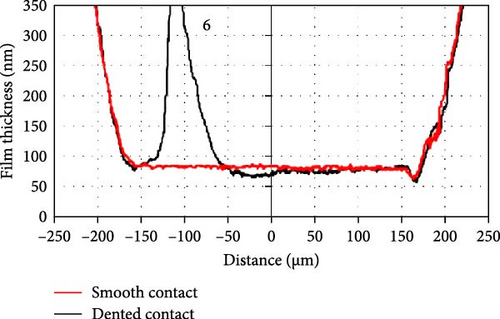
Krupka et al. [72–81] performed similar experiments, monitoring film thickness in ball-on-disk tests, with microdents or dimples, and the results were found in good agreement with Mourier et al. [71]. They observed that the shallow microdents (<500 nm) within the lubricated contact resulted in almost no film thickness reduction (Figure 11). In the case of deeper microdents, the piezoviscous behavior does not exist since the pressure was very small or even close to zero. Hence, lubricant trapped in the microdents will not have sufficient viscosity to separate the surfaces. Krupka and Hartl [77] reported the beneficial impact of surface microcavities in starved nonconformal contact under pure rolling conditions.
Mourier et al. [50] presented two conditions to be satisfied to get beneficial distribution of the film thickness in the presence of microdimples. The first one is that there shall exist a contact zone, where the film thickness is higher than the central film thickness of smooth surfaces (Figure 11b, distance in the range of −150 to −50 µm). The second condition is that the local film thickness shall be nowhere lower than the minimum film thickness (in the constriction zone). The lubricant in the shallow dimples undergoes a pressure decrease, resulting in a decrease in the local viscosity restricted by the shallowness of the dimple. Since the timescale of this transient phenomenon of pressure decrease is very small, a significant variation in normal load-carrying capacity need not be present. The increase in film thickness shows an almost linear behavior with increasing depth of dimples up to crater depths equal to the central film thickness range and decreases at higher crater depths.
Gachot et al. [82], based on the numerical assessment by Dobrica et al. [83], reported that the optimum height of the textured cavities shall be around 40%–80% of the minimum film thickness, and the area coverage of around 30% was optimum for low convergence plane-inclined bearing. From the EHL simulation, Kelley, Poll, and Pape [34] reported that microtextures with a depth range of 10–30 µm do not improve the hydrodynamics of the system. However, their experiments with microtextured (deeper dimples) angular contact ball bearings with starved grease lubrication under oscillating conditions showed an improvement in friction torque [34]. The positive effect of deep dimples in holding more grease near the contact might have balanced out their negative hydrodynamic effect. This implies that the reduction in friction and wear was caused by the replenishment of grease by the microreservoir action of dimples.
2.4.2. Influence of Texture Diameter and Aspect Ratio
For nonconformal contacts, dimple size is determined by the Hertzian elastic contact dimensions. The dimples with a diameter larger or smaller than the contact width may result in a significant difference in film thickness or load-carrying capacity. Vilhena et al. [84] observed that when the diameter of micropores is of the same order as the contact width, the contact area fully encloses the pores. Such micropores are not capable of feeding lubricant into the contact and have a detrimental effect on friction level with increased wear at the contacts. In EHL point contacts with microdimples, experiments have shown film thickness increase for dimple diameter substantially narrower than the contact width and film thickness reduction for sizes larger than the elastic contact zone. Hence, the dimple diameter shall be lower than the Hertzian contact width.
Wos, Koszela, and Pawlus [4] performed pure sliding tests and reported that for boundary lubrication regimes, the cavities might aid lubrication when the lubricant could escape from the pockets into the contact area and also act as wear traps, which might be facilitated by large dimples (dimple diameters larger than elastic contact width). Hsu, Jing, and Zhao [85] discussed self-adaptive texture design for friction reduction across lubrication regimes. They reported that small (dimple diameter smaller than contact width) and deep dimples benefited in mixed/boundary lubrication regimes. Under HD/EHL regimes, shallow dimples are preferred, whereas under boundary lubrication, deep dimples are beneficial [50, 82]. Therefore, compound surface textures with a combination of shallow and deep dimples may be employed for operating conditions with varying lubrication regimes. Sedlacek et al. [86] observed that for textured surfaces, a combination of increased kurtosis and more negative skewness, obtained by lowering the cavity diameter and decreasing the texture density (higher spacing between dimples), is beneficial for lower friction in boundary-lubricated contacts.
2.4.3. Influence of Texture Area Density
Liu et al. [54], based on studies by Xiong et al. [87] and Rapoport et al. [88], reported that lower textured area density was not sufficient for storing lubricants and had difficulty in generating the hydrodynamic loading capacity. Too high texture area density increases the surface roughness significantly and leads to excessively high contact stress at the texture peaks and high stress concentration at the texture edges, causing a higher wear rate. It is concluded that a texture with moderate dimple density provides sufficient lubricant storage, and its relatively lower roughness is beneficial to the wear life of oil film. Podgornik et al. [89] reported that under starved lubrication conditions, surface textures lead to increased friction due to the obstacles created by the dimples/grooves present at the mating surfaces. This happened when the sizes of the dimples/grooves were of the same order as that of the contact size, i.e., Hertzian elastic contact width.
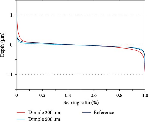
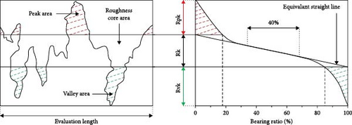
A higher area density of textures in a surface increases the mean roughness and reduces the real area of contact. The height distribution of a surface can be studied using the bearing ratio curve [90] or Abbott–Firestone curve (Figure 12). For small area density (~10%), the bearing ratio curve of textured surfaces with dimples has a similar shape to the untextured reference surface since the surface is modified only at dimple locations and most of the surface remains nearly unchanged for the small dimple area ratio. Higher values at both ends of the curve represent a larger volume near the topographical maximum and minimum, caused by concentrated sharp edges (burr height) of the dimples and the dimple depths, respectively. The dimple patterns present larger values of valley height of the profile, which is termed “reduced valley depth” (Rvk). The Rvk value extracted from a bearing ratio curve is a measure of the valley void volume and can be used as an index of the ability for lubricant storage. An increase of Rvk indicates a larger valley area, which provides space that acts as a reservoir [91]. Hsu et al. [92] suggested that for assessing the ability for lubricant storage in textures with similar geometry (different shapes with comparable width and depth), Rvk shall be compared, and for different geometries, both the core roughness height (Rk) and Rvk parameters shall be involved (sum of core void volume and valley void volume). For similar geometry, they observed that the dimple patterns could retain more lubricant than the groove-type cross samples (with reference to Rvk only).
2.4.4. Influence of Texture Shape
Studies by Yu, Huang, and Wang [12] reported that under high speed and low load conformal contact conditions, the elliptical dimples perpendicular to the sliding direction showed a better effect on the load-carrying capacity (in terms of hydrodynamic pressure lift) than the cases of a circular, triangle, and elliptical dimple parallel to the sliding direction. Among the triangle dimples, the performance of dimples with the sliding direction such that lubricant is driven toward the base of the triangle was better than that toward the apex. They also discussed the significance of dimple array distribution in terms of a square array or hexagonal array (at varying angles of dimple placement).
Wang et al. [68] reported that the specimen with ellipsoidal pits had the lowest friction COF and best antiwear effect, while hemispherical pits had high friction and high wear. Wahab et al. [13] pointed out that the ellipsoidal texture shape is suitable for applications requiring high bearing performance, and the spherical texture is suitable in applications in which isotropic bearing performance is essential and requires cost-effectiveness in terms of manufacturing. The optimal dimple shape and orientation with respect to relative motion are unique for the given operating conditions and material combinations. In most research on LST, circular dimples are the selected texture pattern because of their isotropic characteristics and convenience for simulation.
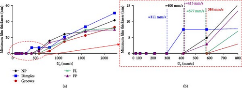
Boidi et al. [44] studied the liftoff speeds (the speed at which stable lubricant film avoids metal–metal contact) for various texture configurations from optical interferometry measurements. As shown in Figure 13, dimple textures showed the lowest liftoff speed among the tests (compared to grooved textures), which implies the dimple textures arrived in the EHL condition at the lowest entrainment speeds.
2.4.5. Influence of Texture Quality and Profile
The quality of the textured surface in terms of remelt surfaces near the textures is critical to attaining the desired tribological properties. During the LST process, due to the laser heating, metal expels in liquid form and gets resolidified at the dimple edges and dimple bottom. Such edges may act as stress raisers, increase asperity interactions, and thereby cause an increase in friction and wear. Such remelted edges may have higher hardness compared to surrounding surfaces and cause abrasive wear at the contacts. This was found to be the reason for higher specific wear rates of the balls in textured surface-ball contacts in comparison to lapped surface-ball contacts during reciprocating tests (AISI52100 material with 58–60 HRC hardness) as reported by Sudeep, Tandon, and Pandey [28]. Special measures have to be taken posttexturing process to remove the edge burrs. Mild lapping using diamond powder is followed in a few studies. An alternate way is to use fs or ps lasers that produce ultrashort pulses and cause ablation of the metal with minimal HAZs and without any remelt surfaces. Few studies have been done on the role of the profile of dimple textures in their capability to act as microreservoirs and lubricant replenishment systems. Generally, laser fluence has a Gaussian distribution, which is reflected in the dimple profile and has a slope toward the depth of dimples. Sedlacek et al. [86] commented such a wedge-like shape of dimples is beneficial for lower friction in boundary-lubricated contacts due to the easy entrainment of lubricants in and out of the dimples. A non-Gaussian distribution of laser energy can be employed to create dimples with flat bottom and cylindrical walls.
3. Effect of Surface Textures on Rolling Contact Bearings
3.1. Influence on Rolling Contact Fatigue (RCF)
Fatigue failure in rolling element bearings refers to the spalling or pitting of surfaces that occurs when the subsurface cracks grow and reach the surface. In earlier days, the impurities, internal flaws, and inclusions in the material were the weak spots for pitting caused by subsurface stresses. However, with the advent of improved steel manufacturing techniques like vacuum melting/refining (VIM-VAR), the metallic inclusions are very minimal. Presently, the surface-induced pitting is more common, and it occurs mainly due to lubrication issues like insufficient lubricant film and the presence of contaminants in the lubricant. Traction at the contact surfaces, which involves rolling motion accompanied by increased sliding (contact slipping), results in higher subsurface stresses with its peak point moving toward the surface. Rather than subsurface, the point of incipient fatigue failure is thus on the surface itself where the EHL film may already be under attack from an adjacent surface or wear debris. Higher levels of vibrations in the bearings also accelerate fatigue failure [11, 82].
3.1.1. Mechanism of RCF Improvement and Effect of Dimple Geometry
Textured surfaces can ensure lubricant availability, and it tends to move the boundary regime of operation toward lower speeds and higher loads. The improved film thickness in the dimples also increases the film damping in the bearings, reducing the vibrations. The wear debris, if any, will be trapped inside the dimples thereby reducing three body abrasions, further increasing the fatigue life. A dimple size shall be selected such that it ensures lubricant film thickness but maintains minimal variations in the contact pressure. Sudeep et al. [94, 95] observed a reduction of vibrations in the presence of dimples. Akamatsu et al. [96] reported enhancement of fatigue life in needle rollers having microdents (microtextures) due to increased lubricant film thickness under poorly lubricated contact. Samanek et al. [97] reported the enhancement in fatigue life under combined rolling–sliding conditions with mechanically indented steel rollers having shallow dents of 400 nm depth when operated in a mixed lubrication regime. They also observed an increase in fatigue life with increasing dimple area density. Ai and Nixon [98, 99] studied the role of texture slope and area density on fatigue life in rolling contacts. Volchok, Halperin, and Etsion [100] observed that in sliding contacts, laser-textured surface features almost doubled the fretting fatigue life as it allowed easier escape for wear debris from the contact zone into the microdimples. Zhai et al. [101] reported that the effects of surface dents on the fatigue life of the rolling contacts may depend on the regime of lubrication in which the contact is operating, and the fatigue life enhancement is likely due to the reduction of local traction at asperity contacts through the “oil pot” (microreservoir) effects of the dents. The possible contact pressure variations (or pressure rippling, as termed by Zhai et al. [101]) under heavily loaded EHL contacts may increase the subsurface shear stresses and may become detrimental to the fatigue life.
Proper selection of dimple geometry is vital in determining the fatigue life and performance. Vrbka et al. [102] investigated RCF of surface textured nonconformal rolling–sliding contacts under mixed lubrication conditions and observed that RCF is influenced by the size and density of the microdents in contact. They showed that shallow dimples of depth <1 μm with higher area density increased the fatigue life even at high loads. It may be noted that in all studies mentioned above having improvements in fatigue life, the dimple diameter was maintained smaller than the Hertzian contact size.
3.1.2. Effect of Residual Stress and LST on RCF
The nature of residual stresses in the material posttexturing is critical for fatigue life. LST increased the residual stresses of tested surfaces and the surface with more textures (more area density) showed larger residual stress. The residual stress generated in the laser texturing process is mainly due to the thermal stress from high temperatures during laser heating. Few studies in gray cast iron have shown that the residual stress postlaser processing is compressive and it can improve the wear performance [103]. The nature of the residual stress depends on the elastoplastic deformations induced in the material, which is determined by the texturing process, whether it is by instantaneous ablation or a combination of melting, vaporization, and solidification. Wang, Yan, and Chen [103] reported the largest residual stress for elliptical dimples compared to circular and grooved textures. If tensile residual stresses are produced in the laser texturing process, fatigue life will be shortened (as cracks will open up in the presence of tensile stress), and it affects the tribological behavior of the components. Han et al. [104], in their review, reported that in LST, only a small amount of material is removed, and the heat-affected zone is confined to a thin layer at the top of the material surface. The thermal cracks that can be formed are very small (in the range of a few micrometers in depth) and will not extend into the bulk. Based on studies on static loading, it is claimed that the mechanical properties of the bulk material will not be much influenced by these small cracks. However, considering the sensitivity of fatigue life to surface defects, these cracks may act as stress raisers, and care needs to be taken to reduce such cracks. Such minute cracks lead to a reduction of fatigue life even under residual compressive stresses.
Laser texturing with fs or ps lasers produces minimal HAZs and related cracks. Hence, texturing with such ultrashort pulsed lasers is preferred for improved fatigue life. Researchers have tried to reduce the residual stresses and HAZs by LSP technique (which involves material displacement rather than material removal), laser ablation under water, etc. Luo et al [24] introduced compressive stresses at laser-irradiated zone by LSP process for improved fatigue life of the component. The LSP process performed postlaser ablation changed the nature of the residual stresses in steel materials from tensile to compressive. Another approach to increase the fatigue life in boundary lubrication regimes is to generate protective tribofilm on the surface by the introduction of certain lubricant additives.
The use of surface textures in rolling element bearings is still rare compared to other machine components, mainly due to concern about their potential detrimental effect on RCF life [105]. However, few available literature show no negative effect on the fatigue lifetime of the ball bearings. Gauda et al. [106] reported faster initiation of fatigue failure in conventional ball bearing compared to microgrooved radial ball bearing, operating in dry condition, and the “wear debris trap” action of the microtextures is identified one of the main reasons for the life improvement. Hsu et al [92] reported a threefold increase in fatigue lifetime for the laser-textured thrust rolling bearings with ZDDP lubricant additive. This is attributed to the ability of the textured surface to retain lubricants within the contact, which ensures sufficient lubrication under high-load conditions, combined with the enhanced formation of the ZDDP tribofilm that prevents direct contact between surfaces. This implies that fatigue life enhancement is a synergetic effect of surface textures, lubricants, and its additives. From the above discussions, it is clear that it is essential to perform application-specific endurance tests with textured surfaces and to ensure it meet the required fatigue life.
3.2. Effect on Vibration
A review of the available literature shows that the overall vibration levels in the tribocontacts changed in the presence of surface textures with a marginal decrease in contact resonance frequency but with a drastic decrease in associated amplitude.
3.2.1. Effect on Vibration Frequency
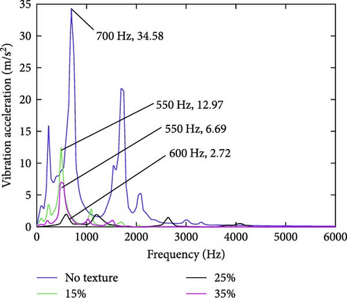
Liu et al. [54] noted a decrease in the peak resonance frequency of the frictional vibrations from 700 Hz (in nontextured surface) to 550–600 Hz (in dimple textured surface) during steel–steel lubricated nonconformal sliding tests. They also studied the influence of dimple diameter and area density on the vibrational performance (Figure 14). This reduction in frequency may be attributed to the drop in contact stiffness caused by the reduced area of contact in textured surfaces. Sudeep, Tandon, and Pandey [107] performed similar nonconformal sliding tests in steel specimens and reported a higher reduction in contact stiffness (natural frequencies) in large-sized dimples with high dimple area density [94] and at higher contact loads compared to lower contact loads.
3.2.2. Effect on Vibration Amplitude
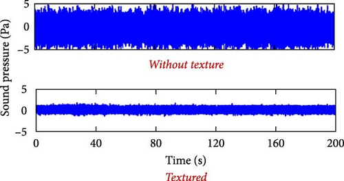
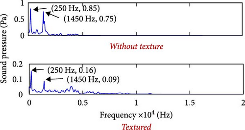
Bhardwaj, Pandey, and Agarwal [108] reported a 21% reduction in vibration amplitude at the rotational frequency in dimple-textured deep groove ball bearings. The reduction in amplitude at resonance could be attributed to increased lubricant retainability due to surface dimples and associated higher lubricant film damping. The reduced friction and improved wear resistance in dimpled surfaces also reduce the vibrations. A similar observation was reported in noise measurements by Wang, Chen, and Zhang [109], where the noise generated in steel–steel sliding contacts was measured under both lubricated and dry conditions. It was found that the noise (RMS of sound pressure) generated from stainless steel (SS) ball sliding against dimple-textured SS plates was much smaller than that generated against polished SS plates without surface texture (Figure 15). The noise reduction was found in the range of 50%–85% depending on the dimple dimensions. Sudeep, Tandon, and Pandey [95] reported higher vibration amplitude damping at 18% area density compared to 9% area density for ф50 µm (lower than Hertzian contact width) and 3 µm deep dimples in AISI52100 (60 HRC) nonconformal sliding contacts at 0.7 GPa contact pressure.
The drastic decrease in the vibration amplitude with only a marginal decrease in contact stiffness of textured surfaces increases the life and performance of the tribocontacts.
Table 1 provide a summary of different works carried out in laser-textured nonconformal tribological contacts focused on pure rolling and combined rolling–sliding motion.
| No. | Author [Ref.] | Material/component | Texture geometry | Type of motion and lubrication | Performance parameters | Observations |
|---|---|---|---|---|---|---|
| 1 | Mourier et al. [50] | AISI52100 steel ball (textured) against Chromium coated silica disk | Circular dimples of diameter 20–120 µm and depth 0.02–10.5 µm | EHL tribometer (0.4 GPa) with varying slide-roll ratios under oil lubrication | Lubricant film thickness |
|
| 2 | Janakiraman et al. [110] | Textured ring against smooth ring (100Cr6) | Grooves of width 210 µm with radial pitch of 420 µm and depth in the range 1–11 µm | Rotating ring test (as in gears) with varying slide-roll ratios under oil lubrication | Frictional torque between mating ring surfaces | Shallow depths yielded lower frictional torque values for a measured range of slide-to-roll ratios |
| 3 | Bhardwaj, Pandey, and Agarwal [111] | Upper ring (stationary) of thrust ball bearing (bearing steel) | Circular dimples of diameter 110 µm and depth 30 µm with area density 11% | Rolling tests in bearing test rig (0.4–0.6 GPa, 30 min) under grease lubrication blended with MoS2 particles | Frictional torque, vibrations, temperature contours |
|
| 4 | Hsu et al. [112] | Washers in cylindrical roller thrust bearing (100Cr6) | Periodic cross-like surface patterns of depth 1–2 µm and periodicity 30 µm | Cylindrical roller bearing test rig (2 h) under boundary lubrication (20 rpm) at high temp (80°C) and high load (1.92 GPa), oil lubricated and additive with 0.02 wt% ZDDP | Coefficient of friction, mass loss in tribo-elements |
|
| 5 | Kang et al. [113] | Textures on camshaft (cast iron) against untextured roller (bearing steel GCr15) | Circular dimples of diameter 70 µm and depth 8 µm with area density 10%–17% | Engine level durability tests (300 h) at engine-rated speed (2200 rpm) and load with oil lubrication | Wear in cam |
|
| 6 | Vidyasagar, Pandey and Kalyanasundaram [69] | The inner ring of a radial ball bearing (bearing steel) | Bionic textures (snake skin type) with 35% area density | Rolling tests in bearing test rig (1.2–2.5 GPa, 500–1400 rpm, 2hr) | Frictional torque, temperature contours, vibrations |
|
| 7 | Kelley, Poll, and Pape [34] | The inner ring of the angular contact ball bearing (ACBB) | elliptical dimples of 750 µm × 30 µm (major × minor axis) and depth 10 µm | Pivoting motion of ACBB (1.5 GPa) with grease lubrication (30% of free volume) | Frictional torque | 50% reduction in frictional torque and reduced wear |
| 8 | Kelley, Poll, and Pape [34] | Inner race flange of tapered roller bearing | Circular dimples 30 µm deep | Rotation test (30 min, 10 rpm, 0.5 GPa) under starved grease lubrication (10% of free volume) | Frictional torque | 5% reduction in frictional torque in the final 10 min of the test |
| 9 | Boidi et al. [44] | AISI52100 steel ball (textured) against steel discs/Chromium coated silica disk | (i) Circular dimples of dia 50 µm, depth 0.1 µm, area density 14% (ii) Continuous grooves of width 35 µm, depth 0.1 µm, area density 21% (iii)/(iv) Longitudinal /Perpendicular grooves of width 7 µm, depth 0.4 µm, area density 47% | Rotating ball-on-disk (0.6 GPa) with varying slide-roll ratios (5%–180%) under oil lubrication at 40°C | Friction and lubricant film thickness |
|
| 10 | Hsu et al. [92] | Washers in cylindrical roller thrust bearing (100Cr6) |
|
Cylindrical roller bearing test rig (2 h) under boundary lubrication (20 rpm) at high temp (60°C) and high load (80 kN), oil lubricated and additivated with 0.05 wt% ZDDP | Mass loss in tribo-elements | Among the four types of textures and reference bearings, the cross texture with a periodicity of 30µm showed the least mass loss and maximum wear protection |
| 11 | Hsu et al. [92] | Rings of thrust ball bearing (100Cr6) | Periodic cross-like surface patterns of depth 1.1 µm and periodicity 30 µm | Thrust ball bearing test rig under boundary lubrication (750 rpm) at high temp (90°C) and high load (3.5 GPa), oil lubricated and additive with 0.05 wt% ZDDP | Fatigue life of rolling bearings under boundary lubrication |
|
| 12 | Long et al. [27] | Shaft washers in cylindrical roller thrust bearing (100Cr6) | Circular dimples of diameter 200/250/300 µm and depth 4/8/12 µm with pitch 890 µm | Vertical universal wear test rig (0.54 GPa, 250 rpm, 5 h) with oil lubrication (starved) | Frictional torque and wear under starved lubrication |
|
| 13 | Wang and Zhang [114] | Outer ring of tapered roller bearings | Circular dimples of diameter 60/100/200 µm, depth 5/10/20 µm and area density 6/12/24% | Vertical universal wear test rig (2.6 kN, 250 rpm, 8.6 h) with oil lubrication (starved) | Frictional torque and wear under starved lubrication |
|
4. Means to Achieve Precise Microtextures in Nonconformal EHL Contacts Through LST
The tribological benefits of surface textures in nonconformal EHL contacts have been discussed. For consistent operation of such contacts in a complex EHL environment, it is vital to have precise microtextures on the surface. Among the various methods discussed in the introduction, LST is an advanced production-friendly technique for creating repeatable precise microtextures.
- •
Reduction in stiction
- •
Increase in adhesion and mechanical interlocking
- •
Control of wettability properties or liquid retention ability (anti-icing)
- •
Control of drag forces in aero-/hydrodynamic application (reduction in wall shear stress and skin friction drag)
- •
Control of friction
- •
Specific applications like improving boiling heat transfer
- •
Improvement of aesthetic appearance in terms of optical properties like chromatic variation and reflectance in lighting optics
- •
Promotion of tissue in-growth in biomedical prostheses
- •
Microfluidics research (cell biology)
- •
Multiscale textures for self-cleaning, oil–water separation, water repellency (as in lotus leaves), friction anisotropy (as in snakeskin), and creating antifouling/antibacterial surfaces.
- •
Noncontact fast process (rapid fabrication and retains material strength)
- •
Environment-friendly (no consumable chemicals and dust-free)
- •
High efficiency (no tool wear) and high repeatability with high processing flexibility
- •
Provides excellent control of the shape and size of textures with good dimensional accuracy
- •
Applicable to different materials (plastics, glass, metals, and ceramics)
- •
Does not affect the bulk properties of the material (little thermal influence on the substrate)
Nevertheless, LST comes with challenges like (for steel surfaces) variations in dislocations and residual stress distributions, formation of different carbide types, heat-affected zones (HAZs), and related hardening effects, making it more brittle and creating bulges/burrs/sharp edges around the created textures.
4.1. LST Working Principle
LST, as its name suggests, uses a laser beam to create texture on the surface. A laser beam is monochromatic (unique wavelength), coherent (photons having the same phase and polarization), collimated (does not disperse with distance and can be focused to a small part with low beam divergence), has good directionality, and high brightness/radiance. Due to these properties, a laser beam is capable of focusing a high concentration of energy on an extremely small spot.
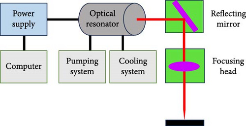
The main components of the LST setup include an optical resonator (laser source), pumping system, cooling system, reflecting mirrors, and focusing head with the associated electronic and computer control system. The optical resonator, which is the laser source, incorporates the active medium and the optics. The active medium consists of a combination of particles that stimulate the emission of laser radiation when they are excited through the modification of energy level states. The pumping system enhances the excitation of particles in the active medium and develops laser emissions. By amplifying the radiation, the optical resonator (laser source) generates a concentrated beam of energy. The output mirror in the optical resonator is partially transmissive through which the laser beam comes out, which is reflected and focused using a lens in the focusing head. The cooling system, used especially in high-power lasers, prevents overheating effects on the system. The electronic and computer control system provides the power and coordinate the different systems [120]. Figure 16 shows a schematic of a laser texturing setup.
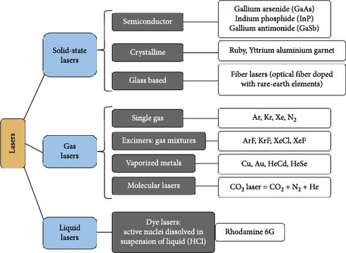
The different classification of lasers based on the active medium (that stimulates the emission of laser radiation when excited) is given in Figure 17, among which solid-state lasers are mostly used for LST applications.
4.2. LST by Laser Ablation
Most of the studies for precise microtextures by the LST process utilize laser ablation with pulsed laser beams. Laser ablation involves the removal of material from a substrate by direct absorption of laser energy through rapid vaporization or sublimation. During the laser ablation process, localized material loss is achieved, resulting in a surface texture with specific design patterns, such as microdimples or grooves. Laser ablation is dependent on the absorption mechanism, material properties, microstructure, morphology (nature of electron and lattice in the material), the presence of defects, laser parameters, and the surrounding environment. The laser parameters that determine the amount of material vaporization are laser wavelength, pulse energy, pulse duration, frequency, and number of pulses. The removal capacity and removal rate of material are not influenced by substrate hardness but by factors such as absorption, thermal conductivity, or thermal capacity [121].
Laser devices use a continuous wave or short-pulsed wave. The continuous wave type provides uniform energy onto the material surface continuously until stopped, while the pulse type involves intermitting pulsing, which allows a higher peak power to be achieved. The pulse duration is short enough (lower than milliseconds) to transfer new energy to the target area before the dissipation of energy conveyed by the previous pulse. Pulsed lasers are classified based on the pulse duration—millisecond (ms), microsecond (µ s), nanosecond (ns), ps, and fs lasers. Millisecond and microsecond pulses are long pulses, and nanosecond pulses are short pulses, whereas ps and fs pulses are ultrashort pulses. The pulsed operation generally minimizes heat input to the bulk and can create a high aspect ratio and sharp-edged microscale features.
4.2.1. Ablation With Long Pulses
The governing ablation mechanism for longer laser pulse width (> ns) is thermal ablation, and it leaves explicit marks of melting and changes in material structure due to the influence of heat. Also, under long pulses, the surface tension gradient of the molten pool drives the liquid away from the hotter center, creating a depression in the center and a raised rim of displaced material at the perimeter, forming a bowl-like shape [122].
4.2.2. Ablation With Short Pulses
Ablation caused by nanosecond (short pulses), ps, and fs lasers (ultrashort pulses) is called cold ablation since the material is vaporized so fast that there is no heat-affected zone in the substrate. The energy of short-duration pulses is rapidly accumulated in the material, leading to its faster vaporization. These pulses strike the material with high energy concentration in such short times that the material does not get the time to transfer the energy to its surroundings thus resulting in ablation. For ablation processes with short pulses, the heat conduction into the interior of the processed material is neglected. The fs laser produces a clean texture without any raised material/burrs at the edge of textured features. Such raised edges/edge burrs are usually seen in long pulse lasers, which require post-LST lapping for their removal [117]. The sample processed by fs laser exhibited the smoothest surface with the sharpest dimple profile as compared to those processed by millisecond and nanosecond lasers [45].
4.3. Effect of Laser Beam Parameters in LST
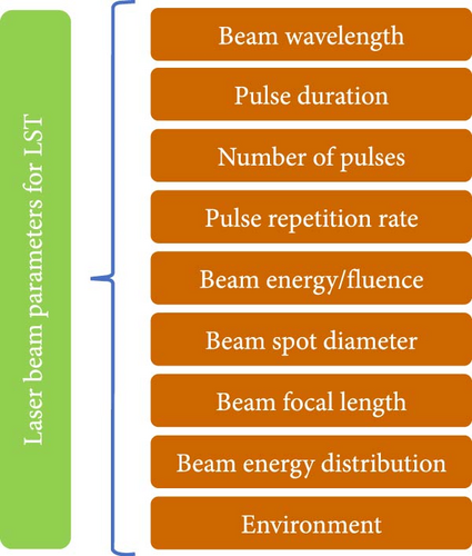
The functional parameters that determine the shape, size, and metallurgical/morphological characteristics of dimples/grooves created with LST include the wavelength of the laser beam, pulse duration, pulse repetition rate, beam energy (fluence or power density), beam focal length, beam spot diameter, quality of beam (M2), and laser beam distribution (Figure 18).
Beam wavelength: The texture resolution (minimum feature size) depends on the wavelength of the laser source used, as described by the diffraction limit [62]. An increase in laser beam wavelength results in a smaller photon energy. As inferred by Prasad, Syed, and Subbu [123], shorter wavelength creates deeper dimples (small diameter with higher depth), whereas higher wavelengths create higher HAZs, measured in terms of the material hardness and its variation with respect to the distance from dimple circumference. Ezhilmaran, Vasa, and Vijayaraghavan [52] reported higher hardness variations near the dimples in hard molychrome coating after nanosecond laser ablation with a laser of wavelength 1064 nm compared to the laser of wavelength 532 nm.
Pulse duration: The shorter the pulse duration or pulse width, the higher the ablation efficiency and aspect ratio of the microfeatures (higher depth with lower lateral dimension), but with longer processing time. Zhang et al. [55] compared the cross-section profiles of the surface textures fabricated with different laser pulse duration in hardened stainless steel and found that the bumps (burrs) at the dimple edges decrease in the order ns > ps > fs. The thermal diffusion length, being proportional to the square root of laser pulse width, implies lower HAZ for lower pulse duration.
Number of pulses (NOP): The final depth of the dimple/groove is determined by the number of pulses. With a small number of pulses, the energy of laser interaction is sufficient only for the coarse defragmentation of the material. With an increase in the number of pulses, the participation of mechanisms of thermal character increases. Mourier et al. [124] have experimentally shown that in 100Cr6 steel material with Ti-Sapphire fs laser (150 fs, 800 nm), the first few pulses (1–5) did not affect the surface; for the next few pulses (5–25), the cavity depth increased, and surface roughness decreased. As the NOP was increased to a higher range (20–50), the ablation stabilized, and well-defined geometries with straight edges and flat bottom were obtained. NOP has a greater influence on dimple depth than dimple diameter. NOP is obtained as the product of pulse repetition rate and exposure time.
Laser pulse frequency or pulse repetition rate: A higher frequency results in a shorter “off time” as the “on time” (also known as the laser pulse width) is constant. A shorter “off time” (higher frequency) results in a shorter duration for heat dissipation after laser irradiation and thus increases the ablation rate.
Beam energy/fluence/energy density: Moderate laser fluences (laser energy per unit area per unit pulse) yield melting, whereas high laser fluences yield ablation which induces significant vaporization. With the increase in beam energy, the material ablation initially increases up to the material threshold ablation limit and further saturates due to the reduced absorptivity as a result of high plasma density formation [123]. For ablation to occur, the laser fluence shall be higher than the minimum ablation fluence of the material, which depends on the heat of vaporization and the optical attenuation COF of the material.
Beam spot diameter and focal length: The area of laser influence on the material is defined by the size of the laser beam spot. In cases where high surface energy density is needed, several different optical elements are used for focusing the laser beam on an extremely small spot. Smaller wavelength beams produce smaller spot diameters and thereby improve focusability. The smallest unit in laser texturing is the size of the focused laser spot, and this is physically limited based on the focusing lens, laser wavelength, and beam quality. Since laser processing typically uses a focused spot, any height variations on the surface to be textured will change the laser spot size at the surface and can have a large impact on the process. The maximum energy intensity is available at the focal plane. As the distance between the material and focal plane increases, spot diameter increases with energy getting distributed in a larger area. For example, height steps can cause the laser spot to suddenly go from in-focus to out-of-focus and move from ablation to melting. Sloped surfaces will cause the laser spot to change from circular to elliptical, reducing the input power and potentially changing the texture geometry.
Beam energy distribution: The profile of the dimples depends on the laser beam energy distribution, which is mostly Gaussian. In Gaussian distribution, ablation is more efficient at the center of the crater than at the rims, thus creating edge effects. Dimple profiles with cylindrical walls and flat bottoms can be made by changing the laser beam distribution to a non-Gaussian profile with optical arrangements to homogenize energy profiles [125].
Environment: The laser texturing environment plays a role in the final shape and hardness of the microfeatures. LST in an ambient environment can lead to oxide formation and higher HAZs, which contribute to microcracking and porosity near textured cavities. In order to reduce the HAZs in long pulses, laser texturing may be done in a vacuum, inert atmosphere like argon gas, or in a water environment. Trtica et al. [126] recorded that texture depth in tungsten with fs laser pulses was higher in vacuum (31 μm) than air (7.2 μm), with a higher surface roughness for texturing in air ambient. This is attributed to the reduction of laser power intensity in the presence of air disturbances. The surface chemical content can also vary with the chosen environment. Yan et al. [127] observed crack-free textures with a reduced amount of splatter deposition in alumina during laser texturing with the surface submerged in water.
Table 2 shows a general trend of the effect of various beam parameters on circular dimples textured on hardened steel surfaces for tribological purposes. However, several parameters are interdependent, and hence, optimization trials of these parameters shall be performed on the actual specimen to get the desired shape, size, depth, and profile of the texture.
| Sl no. | Dimple feature | Energy/fluence | NOP | Beam wavelength | Beam spot diameter | Focal length | Pulse duration | Energy distribution |
|---|---|---|---|---|---|---|---|---|
| 1 | Shallow depth | Low | Low | High | — | — | High | — |
| 2 | Deep depth | High | High | Low | — | — | Low | — |
| 3 | Small diameter | Low | Low | Low | Low | Low | Low | — |
| 4 | Low edge burr | — | High | — | — | — | Low | — |
| 4 | Lower HAZ | — | — | Low | — | — | Low | — |
| 5 | Wedge profile | — | — | — | — | — | — | Gaussian |
5. Numerical Modeling With Textured Surfaces
Numerical modeling has been successfully used in literature to predict the tribological performance of surface textures under hydrodynamic and elastohydrodynamic conditions. The Reynolds equation is used to calculate the hydrodynamic pressure distribution over a single microtexture, and the relationship between the dimensionless film pressure with the dimple aspect ratio and area density is obtained.
5.1. Conformal Contacts
Etsion [128] formulated analytical models of surface textures used in hydrodynamic lubrication of mechanical seals, gas seals, parallel thrust bearings, piston rings, and soft EHL with elastomers. Etsion [128] used a two-dimensional form of the Reynolds equation, to optimize load support as a function of asperity dimensions and asperity area density. Pressure distribution, friction forces across the contacting surfaces, and load-carrying capacities were obtained as the output. By varying the feature parameters, such as dimple diameter, depth, and spacing (or area density), they could optimize textured patterns for the selected operating conditions, in both fully textured and partially textured surfaces. Nanbu et al. [129] numerically studied the effect of different texture cross-sectional shapes (dimple profiles) in lubricated conformal contacts. Liu et al. [130] predicted the geometry of microtextures using finite element-based commercial software by simulating the temperature field during laser ablation and brought out ideal combinations of laser intensity, pulse number, and pulse duration. Dobrica and Fillon [131] showed that for shallow dimples and flows with low Reynolds numbers, the Reynolds equation is good enough rather than Navier–Stokes equation (which involves higher computational effort). It may be noted that the Reynolds equation is derived from the Navier–Stokes equations by neglecting inertia effects and body forces and assuming that the pressure gradient in film thickness direction is zero. Mass-conserving algorithms are used for cavitated films since the occurrence of cavitation is responsible for the asymmetrical pressure distribution over individual pockets which can result in a net load support for textured surfaces.
Gropper, Wang, and Harvey [132] and Kumar and Pandey [133] presented a detailed review of the modeling techniques in the hydrodynamic lubrication of textured surfaces. Sudeep, Tandon, and Pandey [94] studied the contact stiffness by mathematically generating a 3D textured surface using the fractal method and simulations in a commercial FEM package. Wang et al. [134] correlated numerical simulation with experimental results on the effect of textures and their relative orientation in conformal contacts under a mixed lubrication state. The main challenges in the analytical modeling of surface textures under hydrodynamic lubrication involve the numerical instabilities while solving hyperbolic equations generated by combining the Reynolds equation with mass conserving cavitation algorithms, the discretization techniques to address possible film thickness discontinuities, and the averaging techniques of the surface roughness during meshing [132]. Fan et al. [135] based on statistical analysis pointed out that surface textures with three-sigma level manufacturing accuracy can impart higher load-carrying capacity and lower friction COF, compared to lower levels of control in machining precision.
5.2. Nonconformal Contacts
- •
The Reynolds’ equation that relates the pressure in the lubricant film to the geometry of the conjunction and the velocities of the moving surfaces.
- •
The film thickness equation for the computation of the total gap separating the surfaces (resulting from the superposition of the rigid body separation, the initial geometry, and the elastic deformation of the surfaces induced by the pressure in the lubricant film).
- •
The load balance equation requires that the total generated pressure in the lubricant film balances the externally applied normal load.
Because of the high pressures in the lubricant film, the variation of the lubricant properties such as viscosity and density must be taken into consideration by selecting suitable models (Barus model, Roelands model, and Doolittle model). By discretization of these sets of equations, they are either solved separately and sequentially in an iterative approach based on finite difference methods (by direct method, inverse method, or multigrid methods) or solved simultaneously based on finite element approach (full-system approach). The accuracy and converging speed of the solution depends on the discretization method chosen. In solving the EHL model with microtextures, the dimple height is mathematically represented based on its shape and profile, and it is incorporated in the film thickness equation (II equation) along with the rigid body displacement (initial undeformed geometry of the contact) and the elastic deformation of the contacting surfaces (induced by the pressure generated within the lubricant film).
Habchi et al. [137] reported that in the low-pressure region (inlet side) of EHL contact, the Reynolds equation with a Newtonian approach (for lubricant rheological properties) can be used to estimate the film thickness. It depends on the mean entrainment speed and is independent of sliding velocity. However, in the high-pressure zone of the contact, non-Newtonian lubricant rheology shall be considered in solving the Reynolds equation and is dependent both on entrainment and sliding velocity. The pressure spike and the film thickness are reduced when the slide to roll (SRR) is increased (due to viscosity reduction by shear-thinning), while a Newtonian model predicts constant pressure and film thickness profiles for a constant entrainment velocity and any value of SRR. The contact traction is also overestimated in the Newtonian approach. It may be noted that the pressure spike’s height and the contact traction have a moderate effect on the fatigue life, and hence, overestimation leads to reduced fatigue life prediction.
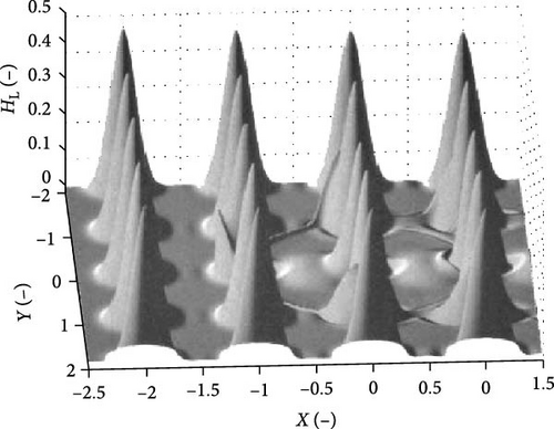
Shi et al. [138] combined numerical and software simulation to study the effect of surface textures and their orientation to obtain subsurface stresses and thereby predict the fatigue life in high-speed heavy-load ball bearings. Tremmel et al. [139] and Marian et al. [140] used transient simulations of microtextured EHL contacts in an extended version of the full-system approach presented by Habchi [136] and implemented them in the commercial software to simulate friction and wear behavior. They modeled the dimples mathematically considering the Gaussian profile of the texture. They further attempted optimizing microtextures by the use of a metamodel to select the best optimized model variant by comparing the COF of prognosis. The prognosis study was targeted for minimum frictional force by varying parameters like the load case, the rheological fluid model, the basic microtexture geometry, and studying the mean friction, maximum contact pressure, and minimum lubricant film thickness for each combination. Kelley, Poll, and Pape [34] mathematically modeled the dimples and implemented them using a fully coupled EHL solver following Habchi, with the two-dimensional Reynolds equation and the load-balance condition using Newton’s method and the finite element method. The geometry of the dimples was modeled using a bump function, which features a smooth decay to zero, thus neglecting pressure spikes due to discontinuous derivatives of the geometry. Qin et al. [141]. investigated the effect of a single circular dent on the film thickness and pressure distribution in EHL point contact using multigrid-based numerical analysis. Taee et al. [142] correlated experimental and computational results in surface textures (achieved by LST) in EHL line contact and demonstrated reduction in friction COF and wear rate by 12%–23% and 50%, respectively. Dumont, Lugt, and Tripp [143] performed a numerical analysis of starved EHL contacts with circular microtextures. They reported analytically the influence of lubricant from the micropits in increasing the film thickness during elastic contact deformations under starved conditions. They showed that the contact deformation and pressure distributions are the same for fully lubricated and starved conditions, but more oil from the micropit finds its way into the contact for starved conditions. They also predicted that as speed decreases, although the film thickness decreases (thereby increasing the degree of starvation), the amount of oil contributed by one pit is expected to become relatively more, leading to an enhancement of the relative benefit of pits (Figure 19).
6. Conclusions and Future Directions
- •
The surface texture dimensions are small for improved lubricant film thickness (25%–40% increase) in EHL contacts, with the texture diameter less than contact dimensions and texture depth in the range of film thickness. An area density of <10% ensures a good overall surface finish, lesser stress concentration, and adequate reservoir volume for lubricant replenishment.
- •
Textured surfaces reduce friction and wear. The drastic decrease in the vibration amplitude with only a marginal decrease in contact stiffness of textured surfaces increases the life and performance of the tribocontacts. The nature of residual stress in the textured surface plays a vital role in its fatigue life. The enhancement of fatigue life in textured nonconformal contacts is a synergetic effect of surface textures, lubricants, and additives.
- •
The trend is to increase the kurtosis with a more negative skewness in the textured surfaces. This is obtained by lowering the cavity diameter and decreasing the texture density. The Gaussian distribution of laser beam energy gives a wedge-like shape of dimples, which aids in easy entrainment of lubricants in and out of the dimples.
- •
The key to success in obtaining the surface texture, with controlled and repeatable geometry/dimensions/profile, is to ensure proper material ablation rather than material melting. Pulsed laser ablation with ultrashort pulse width in the range of fs is proven to be the best option for the laser texturing of hardened surfaces in nonconformal contacts. It yields low heat-affected zones and minimum burr.
- •
Lower wavelength of laser yields higher beam energy. Increasing the laser fluence, repetition rate, and number of spots increases the texture dimensions. Texturing in an inert/vacuum environment or water can result in decreased splatter.
- •
Improved techniques in laser texturing to increase the quality of the textures without the need for any postprocessing like lapping/polishing and to avoid surface hardness variations due to HAZs.
- •
Means to exactly replicate the textures onto precision engineering components like bearing raceways.
- •
Development of standard test methodologies for textured surfaces.
- •
Texturing methodologies on tribological coatings (soft coatings like MoS2 as well as hard coatings like diamond-like carbon (DLC)) and the studies on the effect of such texturing on coating adhesion with the substrate.
- •
Endurance testing of textured surfaces in rolling element bearings to determine the fatigue life. Accelerated life tests are not applicable to bearings operating under EHL.
- •
Studies and life tests on the EHL parameters like film thickness and pressure variations over time with any possible wear in the textured surfaces that may result in reduced dimple depth or increased dimple diameter.
- •
Effect of varying operating conditions on nonconformal contacts with textured surfaces, viz., varying loads and speeds, zero—cross-overs (changing rotation directions), oscillations, and skidding associated with accelerations/deceleration cycles at high speeds.
- •
Mathematical models with user-friendly graphic user interfaces to accurately simulate textured EHL contacts under varying operating conditions.
Conflicts of Interest
The authors declare no conflicts of interest.
Funding
The work was funded by IIT Madras Institute NFIG with grant number SB22230566MENFIG00900.
Open Research
Data Availability Statement
Data will be made available on request.


