Model to Predict Polymer Fibre Diameter during Melt Spinning
Abstract
Polymeric materials were evaluated with regard to their spinnability and respective fibre diameters. A modified single fibre spinning device was firstly used to derive a novel generalised model, utilising process parameters (die diameter, throughput, and stretching relevant take-up pressures) and material properties (zero shear viscosity) to predict the diameter of polymeric fibres on the basis of four different polymers. Further evaluation of the resulting power law dependence was conducted on filaments produced via conventional melt spinning and meltblown processes. Fibres produced on the pilot machines showed close agreement with the model equation with only the need to adjust an easily calculable device dependent factor. The outcome of the presented work is a user-friendly model of high practical relevance, which can be used to predict the diameter of amorphous and semicrystalline polymeric fibres, independent of material and machine used with sufficient accuracy for fast estimations.
1. Introduction
Melt-spun polymeric fibres are widely used in numerous applications, e.g., hygiene products [1], filtration, transportation, construction, and apparel and medical products [2]. In potential utilisations, the properties of the individual fibres (e.g., fibre strength) and those emerging from the complex structure and entanglements in nonwovens and woven fabrics (e.g., pore size and fibre bonding) as well as the possibility for further processing are dominantly impacted by their diameter [3–5]. Those effects have been established by several studies over the past decades. The determination of fibre diameters utilising simulations and models has, consequently, been an important and complex topic in research.
Melt spinning and melt blowing are of great commercial importance due to the ability to produce nonwovens in the micrometer regime. The aforementioned processes have much in common. The polymer granulate is molten and extruded through a small die or a spinneret of multiple die holes. In the case of melt spinning, the filament is cooled by secondary air and stretched by process air before it is collected on a conveyor belt to form a nonwoven by post treatment, e.g., calendering. In the case of melt blowing, hot and high velocity air is used to prolong the material’s solidification and thus elongate the polymeric fibre over an extended length (compared to melt spinning). Therefore, slightly lower fibre diameters in the range of 1-10 μm are producible.
The first commercial usage of melt spinning dates back to 1930 with Du Pont starting to utilise its potential [6]. 30 years later the first mathematical models were developed, especially by Ziabicki, Ziabicki and Kedzierska, and Kase and Matsuo [7–12]. Over the years, the basic equations of momentum, continuity, and energy balances that apply to a spinning threadline have been further improved by considering higher molar mass, viscoelastic fluids, and deformation rate [13–14]. In addition, heat transfer, inertial, and air-drag effects have been included in later works [15–16]. Due to the lack of a fixed end point that can act as a boundary condition for the mathematical models, the simulation of the melt blowing process is particularly complex (in the case of melt spinning, this is the take-up by a haul-off or aspirator). This problem was first solved by Uyttendaele and Shaumbaugh by establishing a freeze point where quenching is low due to the solidification of the fibre [17]. A comparison of the simulations presented in Uyttendaele and Shaumbaugh’s work with experimental data was conducted by Bansal and Shambaugh [18]. Their results intriguingly displayed a disparity between simulated and measured temperature. However, the fibre diameters are matched closely. A possible explanation for simulation errors is the description of the fibre as a one-dimensional object. However, a one-dimensional description is often used, due to the small diameter, as a reason to neglect heat transfer and to assume that forces only act in the axial direction [19–21]. To achieve an even higher accuracy of the fibre prediction, those models can be expanded to the 2D and 3D models, which adds further complexity and computational time [22–24]. Material parameters such as density, viscosity, and specific heat capacity require determination by additional experiments. For semicrystalline materials, further models and material parameters are to be implemented due to the crystallization process occurring during solidification [25–28]. This complexity may overstrain practical use by many industrial companies. However, to the best of our knowledge, simplified models for a first rough but sufficiently accurate estimation of the final fibre diameter cannot be found in the literature and are not emphasized in academia even though they are of great practical relevance.
This work presents the development of an easily and generally applicable model for the prediction of melt-spun fibre diameter produced by melt spinning and melt blowing. For the evaluation of the model, polymeric fibres were fabricated from polymethylmethacrylat (PMMA), polystyrene (PS), polypropylene (PP), and polyethylenterephthalat (PET) using three different industrially relevant spinning devices with several different machine settings (temperature, air speeds, die geometry (L/D), and throughput). The resulting fibres were analysed using images recorded by a light microscope and evaluated with respect to their diameters.
The starting point for the investigation was the spun PMMA fibres with different diameters fabricated with the simplest spinning device. Subsequently, a linear regression model was applied using large amounts of experimental data to evaluate statistically relevant material properties and machine settings. After determining significant parameters, a first model was revealed yielding the viscosity of the polymer, the diameter of the die, the take-up air pressure, and the polymer throughput as significant parameters. Following this, the applicability of the model was evaluated by considering other polymers. Subsequently, data from the second and third spinning devices were used to fine-tune the model prediction towards a general unique formula [29].
The result of the presented research is a simple power law model to predict the fibre diameter during melt spinning and melt blowing, taking into consideration viscosity, die diameter, take-up air pressure, material throughput, and respective machine setup. In comparison to the complex simulations available for this process, (see, e.g., [30–31]), this gives a simple and practical tool for a first estimation of the fibre diameter.
2. Experiments and Materials
2.1. Capillary Rheometer
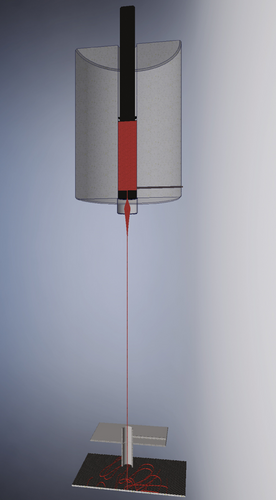
Melt spinning of PMMA, PS, and PET (PMMA 6 N/7 N, Evonik; PS 158 N; and PET RT20, INVISTA Resins & Fibres GmbH) as well as PP (Moplen HP561R, LyondellBasell) was performed with two different spinning devices. The two first polymers (PMMA and PS) were dried for 12 hours at 80°C and PET for 48 hours at 160°C in a vacuum chamber as the polar groups encourage water absorption, which would negatively impact the spinnability. The diameters of spun fibres were investigated with a light microscope (VHX-J250, Keyence, Japan). Spinning was performed with all five materials using a capillary rheometer (Rheograph 2003, Göttfert, Deutschland) combined with an aspirator (scheme in Figure 1). Due to the very limited process parameter range of the amorphous materials, two PMMAs with different molar masses were used to investigate viscosities at different orders of magnitude for the materials. An overview of the process parameters is given in Table 1. Advantages of the capillary rheometer are the tightly controlled process parameters and the validated knowledge of the shear stress on the material due to the extrusion by a piston. In comparison to the second device, described later, this is a discontinuous process with comparatively short spinning length. The aerodynamic stretching took place 53 cm below the die. In addition, the spinning lengths used for PP were 16.5 cm, 35 cm, and 53 cm. The die diameter was kept constant at 1 mm and the die length was either 10 or 30 mm. A melting time of 3 min was applied to ensure that the material was completely molten. Three different piston speeds (for different throughputs) and three take-up pressures were chosen, respectively. The melt temperature was adjusted between the materials (PMMA and PS) and furthermore varied for the semicrystalline materials to enable spinnability and testing of the influence of different viscosities, typically decreasing to approximately 70% of the lower temperature value.
| Material | Temperature (°C) | Air pressure (bar) | Throughput (mm s-1) | Die (L/D) (mm) |
|---|---|---|---|---|
| PMMA 6 N | 240 | 1/2/3 | 0.27/0.53/1.06 | 10/1, 30/1 |
| PMMA 7 N | 240 | 1/2/3 | 0.27/0.53/1.06 | 10/1 |
| PS 158 N | 240 | 1/2/3 | 0.27/0.53/1.06 | 10/1 |
| PET RT20 | 280/290 | 1/2/3 | 0.27/0.53/1.06 | 10/1 |
| PP HP561 R | 210/230/250 | 1/2/3 | 0.27/0.53/1.06 | 10/1 |
2.2. Melt Spinning Pilot Line
The continuous melt spinning of PP HP561R and PET RT20 was performed on a pilot melt spinning line (see Figure 2). For PP, single dies with a length of 10 mm and varying diameter were used at a constant melt spinning temperature of 250°C. Spinning of PET was performed with a multihole die at 280°C. The spinning length was kept constant at 175 cm. Secondary air further cooled the polymeric strand. For the aerodynamic stretching the same aspirator as for the capillary rheometer was used. The loose fibres were collected on a nonmoving conveyer belt with air suction underneath, as postprocessing of the fibres was not needed for this research. An overview of the process parameters is given in Figure 3 and Table 2.
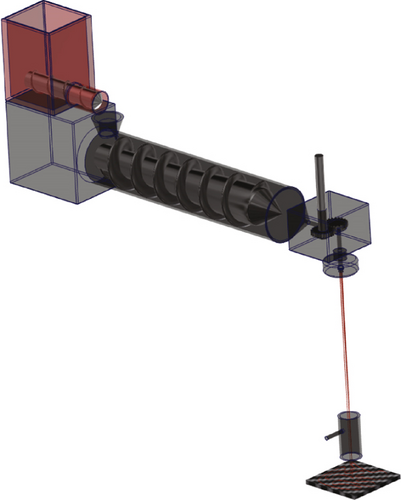
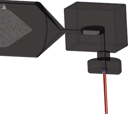
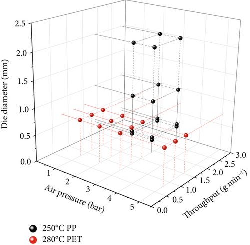
| Material | Temperature (°C) | Air pressure (bar) | Throughput/hole (g min-1) | Die diameter (mm) |
|---|---|---|---|---|
| PP HP561R | 250 | 2/3 | 1.9/2.87 | 0.25/0.3/1/2 |
| PET RT20 | 280 | 1/2/3/5 | 0.78/1.16/1.54 | 0.7 (4 holes) |
2.3. Pilot Melt Blowing Line
The polypropylene meltblown samples were produced on an FET (Fibre Extrusion Technology Ltd., Leeds, UK) meltblown line utilising 14 cm wide spinnerets (scheme of spin head and machine in Figure 4). One of the utilised spin head features 41 round holes with a length of 1.25 mm and a diameter of 250 μm. The hole separation for this head is approx. 3.2 mm. The second head has 81 round holes with a diameter of 175 μm and identical length and a hole separation of approx. 1.6 mm.
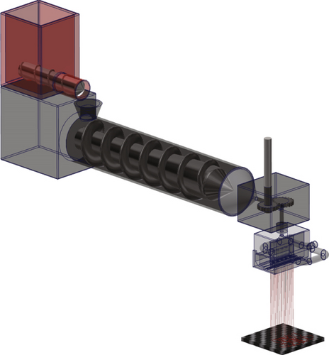
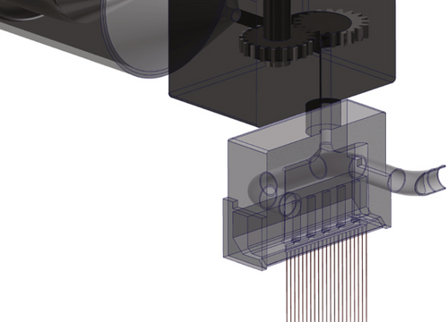
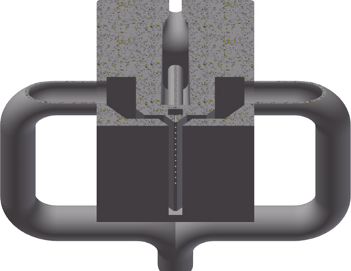
The spun materials were spunbond-grade HP561R and meltblown-grade HL 712 FB. The spinning temperature was varied across the range from 170 to 190°C for the meltblown-grade (further information about spinning parameters in Table 3) and 230 to 250°C for the spunbond-grade. An increment of 10°C was used for both materials and the hot air temperature was 5°C lower than the melt temperature. The DCD (die-collector-distance) was kept constant at 30 cm while the hot air speed, and consequently air pressure, was set at three different values according to Table 3. A conveyor belt with a constant speed of 0.3 mpm was used as the collector applying a constant air suction below the belt located below the die.
| Temperature (°C) | Air pressure (mbar) | Throughput (cm3 min-1) | Die diameter (μm) | |
|---|---|---|---|---|
| Range | 170-190 | 0.14-0.22 | 5-20 | 175; 250 |
| Step | 10 | 0.04 | 5 |
2.4. Oscillatory Shear Rheology
For the rheological measurements, round plates with a diameter of 25 mm and 2 mm height were hot-pressed. The materials were heated to 30°C above their melting temperature and 10 bar pressure was applied for 6 min. Afterwards, they were pressed for 2 min at 100 bar. The whole pressing process was performed in a vacuum chamber to prevent degradation and to achieve bubble free samples.
The rheological characterization was performed with the DHR 3 rheometer from TA Instruments (USA) with a plate geometry (25 diameter, 1800 μm gap). To prevent polymer degradation, a nitrogen atmosphere was applied during the experiments. Frequency sweeps (from 0.1–628 rad s-1) in the range of the processing temperature were performed and afterwards mastered to determine the zero shear viscosity of each material. Oscillating shear experiments with an amplitude range of 0.001% to 100% identified the linear viscoelastic regime at 3% for all materials, which was therefore used as the amplitude for the aforementioned frequency sweeps.
3. Results and Discussion
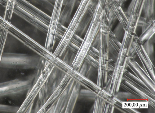
Fibres of two different PMMAs, PS, two PPs, and PET were melt-spun on three different devices presented in the Experiments and Materials. The resulting diameters were analysed using images recorded using a light microscope (see Figure 5). The fibre diameter variation along the MD and CD directions were analysed, and no clear influence was detectable within the expected experimental error.
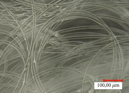
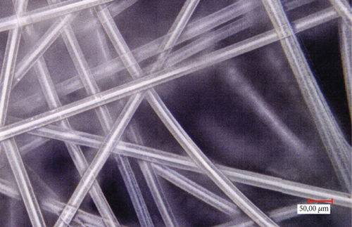
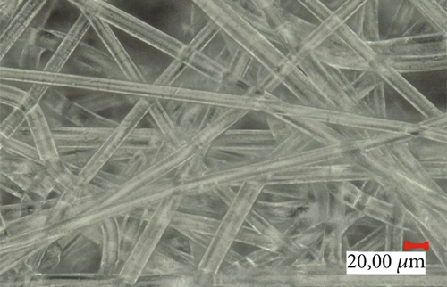
Some parameter combinations lead to unusually high fibre diameters (discussed later on), which are not common for the melt spinning process. Therefore, only fibre diameters below 135 μm were considered to be reasonable for the practical melt spinning process. The results are shown in Figure 6.
The general dependence on the fibre diameter follows intuitively assumed behaviour. Increasing the die diameter or the throughput per die hole leads to a higher final diameter. The same can be stated for an increase in molar mass (or decrease in temperature), which leads to a higher viscosity, while a higher take-up air pressure reduces the diameter of the polymeric fibre. All four parameters have significant impacts on the fibre diameter. Comparison of the experimental results with the model prediction values suggests that there is close agreement in accordance to the corrected R2 value of 0.89 (see Figure 7).
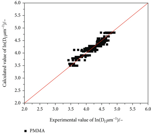
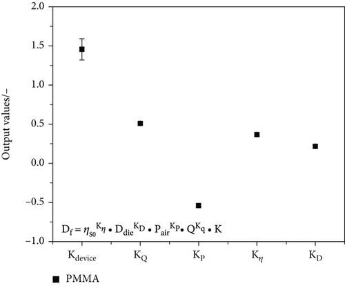
The fact that the fibre diameter deviation of the PMMA model parameter set typically lies at 11% while the experimental error is approx. 8% demonstrates the close agreement of experimental and model data. Nevertheless, for a general model, more data and different materials, which are commonly used in fibre spinning, are needed. Therefore, other materials that were spun on the capillary rheometer are gradually added to the model, which finally leads to 1355 data points with a wide variety of fibre diameters (10-135 μm) that are included in the model. The model parameters determined from incremental augmented data sets are presented in Figure 8.
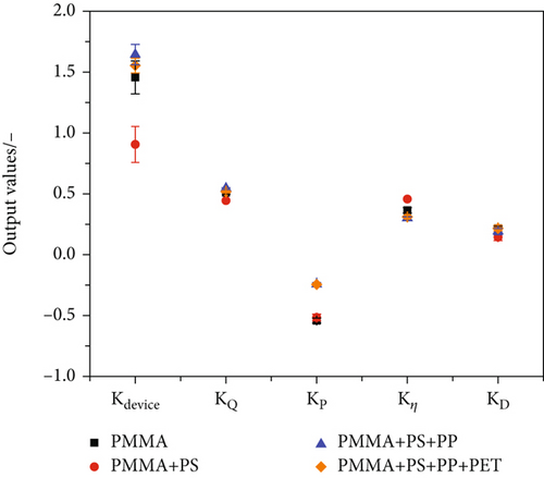
Figure 8 displays only a slight change in output coefficient values with incrementally added polymer. The highest deviation is detectable for the device constant (Kdevice) value after the inclusion of PS data. This can be explained by the difficult spinnability of the material and the high fibre diameters (between 50-300 μm), many data points of which had to be excluded. The rather poor spinnability of the polystyrene material could be related to its flow behaviour. Beyreuther and Vogel [32] identified a correlation between the physical properties of a polymer melt (in combination with the process settings) and the spinnability of said melt. According to their research, the loss tangent (which is calculated to be tan(δ) = G′′/G′) at a storage modulus of 100 Pa can be used to determine the potential spinnability. A loss tangent of greater than five yields potential spinnability, whereas a value higher than ten results in good spinnability. According to our rheological measurements, the loss tangent of the used PS 158 N is in the range of 6-7 (see Figure 9), which can result in poor processability, resulting in high fibre diameter variance and consequently has a strong influence of some settings on the model parameters.
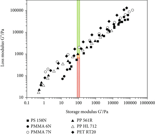
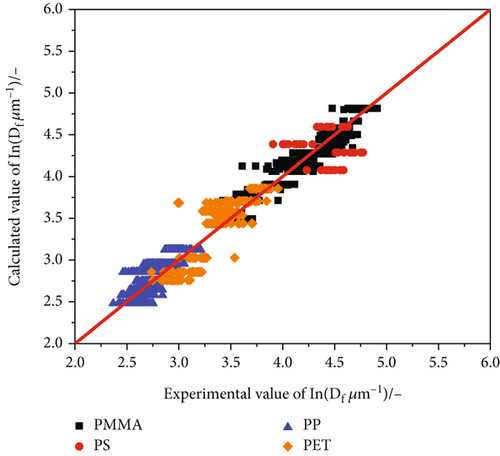
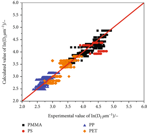
Further optimisation of the model was realised by adding spingrade PP and PET, resulting in reproducible coefficient values independent of the material. The influence of the take-up air pressure was weakened, presumably due to the noticeably lower viscosity of the PP and PET spingrades, which lead to smaller fibre diameters at low take-up pressures. The minimal Fibres of two different PMMAs PET materials (see Figure 8) can be substantiated by their loss tangents, which are located in the green area in Figure 9 (loss tangent greater than 10). The comparison of the experimental and calculated fibre diameters (see Figure 10) with a corrected R2 of 0.93 demonstrates the accuracy of the model.
The approach is to readjust the related Kdevice of the capillary rheometer applying an iterative minimization. By calculating the fibre diameters with Kdevice values of 0 to 2 with an increment of 0.01, the lowest deviation (error calculated according to equation (4)) leads to the closest fitting constant for the implementation of the capillary rheometer. Figure 11 shows the result utilising equation (5) with optimised Kdevice leading to a final fibre diameter deviation of 17.48% instead of 17.44%.
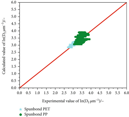
The Kdevice depends on the spinning device and must be determined for each industrial or scientific melt spinning line individually. However, with this method and a few experimental data points, the line-specific prefactor K (see equations (2) and (3)) is easily accessible, as long as viscosity, die diameter, take-up air pressure, and throughput are known, which is normally the case in fibre spinning applications. To prove this assumption, spinning with the PP and PET spingrades used in the capillary rheometer was performed on an industrial near pilot fibre spinning line (see Experiments and Materials). In this case, the spin length is more than tripled and secondary air helps cool the polymeric strand. Additionally, multihole dies enable high throughput variation. Given the known power law correlation, the final fibre diameter was calculated and compared to the experimental values. Considering the new spinning device, a new machine constant had to be determined by using equation (4) and the method mentioned earlier in this work. Intriguingly, in this case, the comparison of model and reality leads to an error of 15.6%. This is even smaller than that calculated for the capillary rheometer data (17.48%) used to determine the model for the capillary rheometer validating equation (5) with regard to a general applicability of this simple model for a first fibre diameter estimation in melt spinning. Figure 12 depicts a comparison of model and experimental data for both materials.
Further confirmation of the applicability was achieved by analysing experimental results of a pilot melt blowing line. A comparable approach to the spunbond pilot machine was applied to compare the calculated values of the power law model with actual measured data. Here, a polymer with distinctly lower viscosity had to be used to run the machine. The previously used PP, which was tested first, resulted in irreproducible data and high variation of fibre diameter for each machine setup due to its inappropriately high viscosity for meltblown applications.
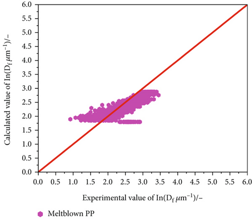
The take-up pressure was then applied through the hot air stream alongside the fibre (see Experiments and Materials). The system can track air stream velocity as well as air pressure, for which the data can be applied directly to the power law model. The result of the predicted (equation (5)) and experimental values is displayed in Figure 13, showing some outliers towards lower fibre diameters. However, this might also be due to the low viscosity material and high number of data points for only one material (1170 data points). Consequently, the deviation between calculated and experimental values is relatively high at 27.8%. Comparison with the variance of the diameter caused by the process itself results in an error of 41.1% (calculated according to equation (4)). Taking the high variation in fibre diameter into consideration leads to the conclusion of high model applicability for the meltblown process.
4. Conclusion
A novel model prediction for the diameter of melt-spun polymeric fibres utilising process-relevant parameters is presented. In order to determine a specific model, a power law dependence of diameter and given parameters was presumed. Consequently, the approach was to logarithmize the experimental values and to apply a linear statistical model with only the main effects. A model is demonstrated to estimate fibre diameter with an accuracy similar to the experimental error as a function of pressure applied to stretch the fibres, die diameter, throughput, and the material-specific zero shear viscosity evaluated from shear rheological measurements. Only one prefactor must be adjusted for each individual spin line. The approach can be generally applied to melt spinning processes including meltblown, where fibre stretching is achieved using process air. The outcome of the presented work is an easily applicable and user-friendly prediction of polymeric fibre diameter based on the power law dependence from process-relevant machine and polymer properties (which are usually controlled or known from data sheets).
Conflicts of Interest
The authors declare no conflict of interest.
Authors’ Contributions
Alexander M. Bier and Michael Redel contributed equally to this work.
Acknowledgments
We acknowledge financial support by the Deutsche Forschungsgemeinschaft and the Friedrich-Alexander-Universität Erlangen-Nürnberg within the funding program “Open Access Publication Funding”. This work was also supported by the German Bundesministerium für Bildung und Forschung (Project VISP 03VP06651).
Open Research
Data Availability
The data used to support the findings of this study are available from the corresponding author upon reasonable request.


