Modelling and Investigation of the Dynamic Behavior of a Penny-Shaped Interface Crack in Piezoelectric Bimaterials
Abstract
In this section, the dynamic propagation behavior of a penny-shaped interface crack in piezoelectric bimaterials is analyzed. The objective of this paper is to use the boundary conditions of the penny-shaped interface crack to study the dynamic propagation of the crack under the action of load, so as to provide some valuable implications for the fracture mechanics of the piezoelectric bimaterials and simulate the interface crack between piezoelectric bimaterials, it is necessary to establish a suitable model and give appropriate boundary conditions according to the actual situation. The elastic displacement and potential equations are constructed according to the structural characteristics of the circular crack. In the case of a given displacement or stress, the Laplace transform and Hankel transform are used to simplify the problem into an integral equation with unknown functions. According to the boundary conditions, the corresponding unknowns are obtained, and the closed solution is derived. The results show that the fracture toughness of a penny-shaped interface crack in piezoelectric bimaterials is related to the thickness of the material, the impact time, the material characteristics, and the electric field. At the same time, it can be found that different materials have different roles in the crack propagation, so it is very important to study the crack opening displacement (COD) intensity factor of the crack for safety design.
1. Introduction
1.1. Background
Piezoelectric materials are widely used to make all kinds of transducers and sensors because of their piezoelectric effects. They are commonly used in electronic, excited light, ultrasonic, hydroacoustic, microacoustic, red external, navigation, biological, and other technical fields. However, the brittleness of piezoelectric ceramic material in mechanical properties will lead to the generation and expansion of cracks from the stress concentrations, leading to the failure of components. It is necessary to analyze the crack propagation process of piezoelectric materials to improve the operational performance of high-voltage electric ceramic elements and predict their active life.
In order to meet the practical needs, experts have used experimental, theoretical, and simulation methods to study the influence factors of piezoelectric materials in the different situations [1, 2]. The forced vibration of a piezoelectric plate with initial stress and the factors affecting the dynamic stability of a prestressed piezoelectric plate are studied [3, 4].
Based on the above situation, research on the fracture mechanics of piezoelectric ceramics has received attention from the experts [5–13]. Influence of incomplete bonding on the dynamic response of prestressed sandwich plate–strip with elastic layers and a piezoelectric core was studied by Daşdemir [14]. The influence of poling direction and imperfection defects of the prestressed system with a piezoelectric core bonded to elastic faces was analyzed [15]. In most cases, the crack is simulated by a penny shape [16, 17]. A 3D problem of a half-space with penny-shaped cracks has been studied [18]. Zikun [19] solved a penny-shaped crack problem and obtained analytical expressions of the stress field and electric displacement field near the crack tip. Using the Dugdale hypothesis and Hankel transform theory, Danyluk et al. [20] analyzed the penny-shaped crack in a thick transversely isotropic elastic layer. Kogan et al. [21] obtained the stress intensity factors of a penny-shaped crack. The plasticity of a penny-shaped Dugdale crack tip in an infinite elastic medium has also been estimated [22].
A penny-shaped crack has been considered in a piezoelectric medium to analyze the coupling behavior [23]. Penny-shaped cracks in 3D piezoelectric media are analyzed by the extended displacement discontinuity method [24]. The Dugdale plastic zone of a penny-shaped crack under axisymmetric loading has been analyzed [25]. Wu at al. [26] studied a penny-shaped crack in a piezoelectric layer sandwiched between two elastic layers with the electrical saturation and mechanical yielding zones. The crack propagation behavior of an infinite 1D hexagonal piezoelectric quasicrystal plate with a penny-shaped dielectric crack has been analyzed [27].
The crack propagation will change into a dynamic behavior with time under an explosion or impact load. Wang et al. [28] investigated the penny-shaped interface crack configuration in orthotropic multilayers under dynamic torsional loading by utilizing Laplace transform and the Hankel transforms technique. The dynamic behavior of a penny-shaped crack in a magnetoelectroelastic materials has been analyzed in detail [29]. A point force method was proposed for obtaining the transient response of dynamic penny-shaped cracks in multilayer sandwich composites [30]. The dynamic behavior of a magnetoelectroelastic material with a penny-shaped dielectric crack under impact loading has been determined [31]. A mathematical expression for the dynamic behavior (open function circular) of a permeable penny-shaped crack in an infinitely porous elastic solid has been presented [32].
In order to overcome the weak characteristics of the piezoelectric effect of a single piezoelectric material and better expand the piezoelectric effect, the piezoelectric double material has emerged, which is better applied in intelligent structures such as transducers, sensors, and drivers, and it has also produced great application and economic value. At the same time, because of its superiority, it has also been studied and analyzed by many experts and scholars [33–39]. Under loading conditions, the interface of piezoelectric bimaterials is prone to fracture due to surface offset. In addition, crack propagation becomes a dynamic behavior when piezoelectric bimaterials are impacted in practice [40]. There are few studies on the dynamic change of a penny-shaped interface crack in piezoelectric bimaterials. Therefore, the dynamic analysis of a penny-shaped interface crack in piezoelectric bimaterials is very important in designing practical engineering applications.
It is well-known that defects such as interface cracks, holes, and dislocations seriously affect the mechanical behavior and change their strength. In addition, the interface crack boundary conditions are of great significance for selecting fracture criteria and predicting crack propagation. In addition, the penny-shaped interface crack, which is the research target of this paper, is a common type of crack, and the dynamic propagation to be studied is also the most practical and research value. However, the dynamic propagation of a penny-shaped interface crack is difficult in experiments and simulations. Therefore, in order to meet the needs of development and safety, the objective of this paper is to use the boundary conditions of the penny-shaped interface crack to study the dynamic propagation of the crack under the action of load, so as to provide some valuable implications for the fracture mechanics of the piezoelectric bimaterials.
1.2. Outline
After the introduction, the model and constitutive equations are described. Section 3 discusses the calculation methods under the Laplace transform and Hankel transform. In Section 4, the dynamic field intensity factors of crack-tip propagation are derived. In Section 5, numerical results are obtained based on the model and calculation. The final section presents some conclusions drawn from this study.
2. Problem Statement and Formulation
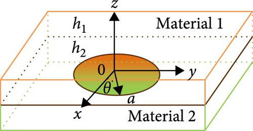
In Figure 1, a penny-shaped interface crack made in piezoelectric materials one and two is considered. The thickness of piezoelectric Materials 1 and 2 are h1 and h2, respectively. The radius of the penny-shaped interface crack is a. Let us analyze the case of the poling direction along the z-axis in polar the coordinates (r, θ, z). The center of the crack is the origin of coordinates, and its region is r ≤ a, z = 0. The names of the parameters can be seen in nomenclature.
3. Solution to the Problem
4. Dynamic Field Intensity Factors
5. Numerical Examples
When the dynamic field intensity factors exceed the corresponding critical value, the crack expands. Some numerical calculations are shown to describe the dynamic behavior of a penny-shaped crack. The material coefficients of the numerical examples are shown in Table 1.
| Material | PZT-6B | PZT-5H | BaTiO3 |
|---|---|---|---|
| c11 (1010 N/m2) | 16.8 | 12.6 | 22.6 |
| c33 (1010 N/m2) | 16.3 | 11.7 | 21.6 |
| c44 (1010 N/m2) | 2.71 | 3.53 | 4.4 |
| c12 (1010 N/m2) | 6 | 5.3 | 12.5 |
| c13 (1010 N/m2) | 6 | 5.5 | 12.4 |
| e31 (C/m2) | −0.9 | −6.5 | −2.2 |
| e33 (C/m2) | 7.1 | 23.3 | 9.3 |
| e15 (C/m2) | 4.6 | 17 | 5.8 |
| ε11 (10−10 F/m) | 36 | 15.052 | 56.4 |
| ε33 (10−10 F/m) | 34 | 13 | 63.5 |
| ρ (103 kg/m3) | 7.55 | 7.5 | 5.7 |
Let us take the inverse Laplace transform as Stehfest [44] proposed. In our example, the stress impact load τ0 is selected to be 4.2 MPa. The parameters relating the electrical and mechanical loadings are expressed by I∗ = e33E0/τ0 and cv = vt. Let us define the dimensional function as F/F0, where F0 is the static COD intensity factor (F is KCOD in Equation (81)).
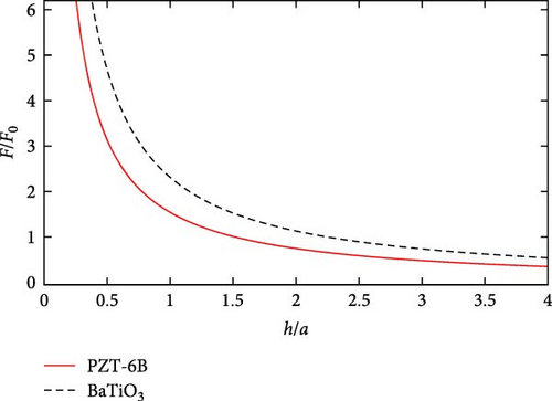
When the double material degenerates into a single material, we can calculate the corresponding value (Appendix B). Figure 2 is drawn to describe the trend of F/F0 relative to h/a (). The two piezoelectric single materials are PZT-6B and BaTiO3, respectively. The F/F0 of both materials decreases monotonically and tends to change smoothly with increasing h/a. On the other hand the changes in the two curves are shown in Figure 2. We can see that the change in the value of the material BaTiO3 is greater than that of material PZT-6B, which in a particular sense implies the correctness of our results.
For the F/F0 plot with E0 change in Figure 3, a thinner piezoelectric layer can be found to cause an increase in F/F0, which means that the contribution of the electric field to the fracture toughness is evident for the thin piezoelectric layer in Figure 3. When h1/a > 2, F/F0 is also insensitive.
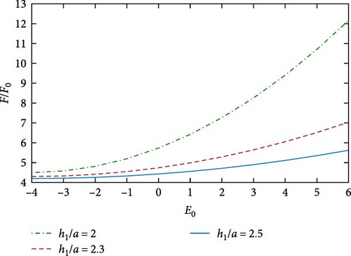
Figure 4(a)–4(c) discuss the influence of the applied electric fields E0 and vt/a on F/F0. Under the impact problem, this time normalization is denoted by vt/a, where v is the shear wave velocity. In Figure 4, for a given pressure τ0, F/F0 increases with increasing of electric fields E0 and vt/a. At a fixed time, it can be found that an increase in E0 will lead to an increase in F/F0, which is consistent with the result shown in Figure 3. For a fixed electric field E0, an increase in vt/a leads to an increase in F/F0. However, we can see that the increase in F/F0 flattens out in the later period. From Figures 2–4 show that different materials play different roles in the crack propagation.
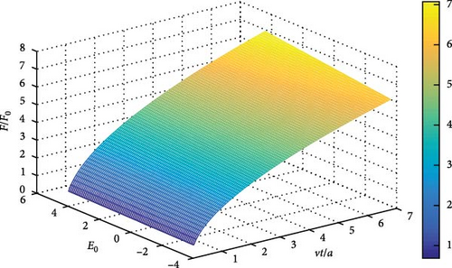
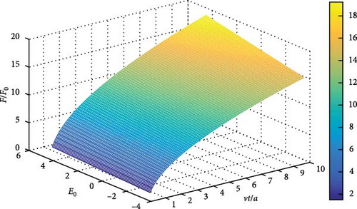
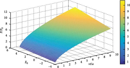
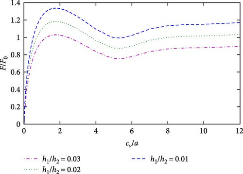
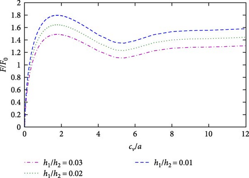
Figure 5 shows that when the substrate is constant, the thicker the material 1, the less influence it has. In other words, when the thickness of Material 2 is constant, the thickness of Material 1 is small, and the COD intensity factor changes greatly, indicating that the thinner of Material 1 when appropriate, the more conducive it is to safe design.
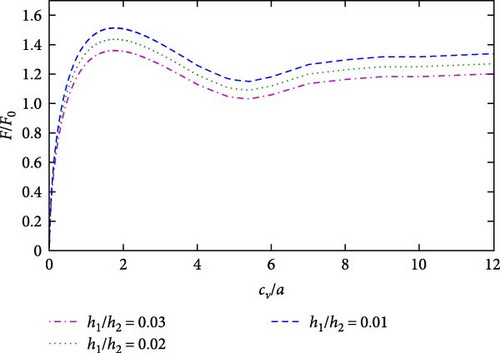
It can be seen from Figures 3 and 4 that both positive and negative electric fields will affect the propagation of cracks. At the same time, it can be found that the COD intensity factor value is large under a positive electric field, while the COD intensity factor value is small under a negative electric field, which indicates that the positive electric field will cause the expansion of the piezoelectric material, while the negative electric field will cause the contraction of the piezoelectric material. This conclusion is consistent with that of the study by Li and Lee [42]. In other words, crack propagation can be controlled by the regulation of electric field.
For the F/F0 plot with I∗ in Figure 6, a thinner piezoelectric layer can be found to cause an increase in F/F0. In addition, observations of Figures 4–6 suggest that the electromechanical coupling coefficient plays an important role in crack propagation: the stronger the electromechanical coupling effect, the smaller F/F0 is.
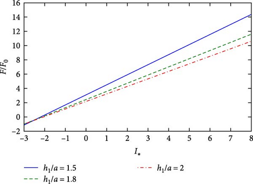
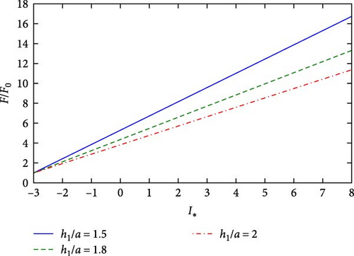
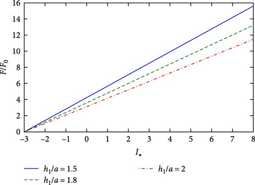
All the c figures in Figures 4–6 studied the crack growth of different piezoelectric bimaterials. By comparing the images, we can find that when Materials 1 and 2 are different, the variation trend of COD intensity of crack growth is basically the same as that when Materials 1 and 2 are the same. That is, different material parameters will affect the change of COD intensity factor, so in practical applications, the appropriate material should be selected according to the actual situation.
It can be seen from Figures 5 and 6 that when the thickness of Material 2 is constant, the thickness of Material 1 is small, and the COD intensity factor changes greatly, indicating that the thinner the material when appropriate, the more conducive it is to safe design.
6. Conclusion
Based on the piezoelectric theory, the dynamic penny-shaped interface crack propagation of piezoelectric bimaterials is analyzed. The boundary conditions are transformed into a nonlinear Fredholm integral equation by using the Hankel transformation technique. Numerical solutions are given. According to the given surface displacement and stress of the layer, the corresponding models are constructed, and the displacement functions that meet the conditions are established. Solving the model, the influences of the electric field, impact time and layer thickness on the dynamic COD are analyzed accordingly. The results show that the COD increases with decreasing h1. At the same time, when the speed v and crack size a are fixed, the COD increases with increasing impact time, and tends to be flat after reaching the peak value. The stronger the electromechanical coupling effect is, the smaller F/F0 is. At the same time, different materials have different roles in crack propagation, so it is very important to study the COD factor of cracks for safety design.
Nomenclature
-
- :
-
- Elastic constants
-
- :
-
- Dielectric constants
-
- :
-
- Radial and axial components of displacements vector
-
- :
-
- Electric displacement
-
- v:
-
- Shear wave velocity
-
- k = 1, 2:
-
- Materials 1 and 2
-
- E0:
-
- Electric loading
-
- :
-
- Piezoelectric constants
-
- ρ(k):
-
- Density
-
- :
-
- Stress tensor
-
- H(t):
-
- Step function
-
- t:
-
- Impact time
-
- τ0:
-
- Mechanical loading
-
- E0∗:
-
- Dielectric load normalization.
Conflicts of Interest
The authors declare that they have no conflicts of interest.
Acknowledgments
This study was supported by the National Natural Science Foundation of China (11972019 and 52275567), Shanxi Provincial Key Research and Development Project (202102090301027), and Shanxi Postgraduate Innovation Project (2022Y668).
Appendix
A. Elements of Matrix [C]
B. The Element Value of Matrix [C] in Single Material
The value of cji corresponds to the value of Cji for the matrix in Appendix A.


