Prescribed-Time Fractional Order Control of DWR via Time-Varying Scaling Function
Abstract
This study focuses on a differential wheeled robot’s (DWR) prescribed-time fractional order position control. Firstly, based on the kinematic model of DWR, a distance-related orientation error is designed using the inverse sine function. Based on this, an improved linear velocity constraint function is proposed. Compared with existing methods, while ensuring the correlation between velocity and orientation error, the multibalance point risk caused by large angle errors is avoided. Then, a prescribed-time fractional order position controller based on a time-varying scaling function is proposed to stabilize the kinematic system of DWR in the prescribed time. This controller can stabilize the position control system of the DWR in a prescribed time by adjusting the prescribed-time parameter, avoiding the infinite gain risk in traditional prescribed-time controllers. Finally, through numerical simulation, we verify that the proposed control law can converge the system status of DWR to the bounded interval in the prescribed time.
1. Introduction
Due to their simple structure and strong stability, differential wheel robots (DWR) have been widely used in intelligent logistics and medical rescue scenes, bringing many conveniences to people’s daily lives [1–3]. For example, the DWR is a mobile base equipped with a flexible robotic arm to complete the pick-up task [4–6]. In some practical applications, especially material-handling scenarios, mobile robots often must reach the target location within the specified time [7]. In these applications, the robot can reduce the distance from the target position by controlling its linear and angular velocities. This motivation, also known as “position stabilization,” has received widespread attention from researchers.
The literature contains a variety of approaches to this topic. In the literature [5, 6], the author studies the maximum load of the manipulator when the flexible manipulator is installed on the mobile robot. The finite element method can be applied to derive kinematic and dynamic equations for moving carriers [5]. Furthermore, reference [6] proposed a new method for path planning for a wheeled mobile manipulator using hierarchical optimal control. Based on the robot kinematic model, the authors of literature [8] use PID control to provide a reference speed for the robot-driving wheel. Literatures [9, 10] have the experiments of the control law in [8]. Compared to the previous works, the linear velocities in [9, 10] consider the orientation error, which ensures that the speed is slow when the robot’s orientation does not meet expectations. Complex technologies are proposed in other studies, such as adaptive [11] or predicting controllers [12], but the settling time of the robot position control system is not precise. However, in practical applications, such as material-handling scenarios, robots need to complete tasks within a limited time [13]. Although the angle error is considered in the velocity design of DWR [9, 10], thereby reducing the nonlinear coupling relationship of the system, it still cannot obtain an accurate association between the stability time and speed. More importantly, if the system’s settling time can be accurately obtained, it can improve the work efficiency of the robot to a certain extent [5]. Conventional finite-time control makes the system stable within a finite time affected by initial values, which is not conducive to practical applications [14]. Fixed-time control provides a prespecifiable upper bound for the system settling time, independent of the initial state value but still influenced by design parameters [15]. In [16, 17], the authors propose a new finite-time control method based on a time-varying scaling function with a monotonous increasing characteristic called prescribed-time control (PTC). The characteristic of PTC is that the system’s settling time can be predetermined within the allowed physical range, independent of the initial state values and system parameters. However, the controller gain of PTC will gradually increase to infinity with the running time, which cannot ensure the system’s continuity after the prescribed time. For this reason, literature [18] introduced a time-varying piecewise function. It proposed an adaptive PTC method for robot systems, but the method did not consider the application of higher-order systems. In [19], a prescribed-time robust differentiator was designed based on an event-triggered approach using finite varying gains. Further, literature [20] introduced a switching scaling function to obtain a prescribed finite time state feedback controller for higher-order systems. Also, in literature [21], a new notion of stability, called triangular stability, is proposed, and triangular stability implies prescribed-time stability. The piecewise time-varying function avoids the infinite gain problem faced at time T by switching in advance, making the system state known after the prescribed time [18–21]. However, due to the sampling time of the DWR control system, when the switching delay is triggered, the problem of reverse gain may occur, causing the system to diverge. Therefore, the PTC method suitable for the DWR position control system is still worth further studies.
- (1)
The novel orientation error and linear velocity constraint functions are provided based on the DWR kinematic model. Compared with [9], the method in this paper not only keeps the yaw angle of the DWR at the target point at zero but also solves the problem of misalignment of the balance point caused by excessive orientation error
- (2)
A time-varying scaling function suitable for the DWR position control is proposed by introducing a fractional power term. When applying this scaling function to the prescribed-time position control of DWR, not only does it avoid the problem of infinite gain, but also the stability time of the DWR position control system can be predetermined by adjusting the time parameter
The rest of this paper is arranged as follows. Section 2 provides the relevant variables for the position control system of the DWR. The prescribed-time fractional order position controller designed in this paper is given in Section 3, and the stability of the proposed controller is analyzed in Section 4. Numerical simulations and discussions are presented in Section 5.
2. System Modeling and the Objective
This section proposes an innovative orientation error, and then, we point out that the position control problem of DWR can be described as the stabilization control of its kinematic model.
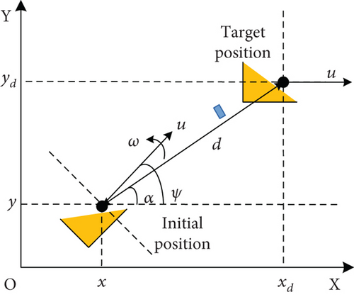
The states x, y, and ψ are the centroid positions and the yaw angle of the robot in the coordinate system, respectively. The u and ω represent the linear and angular velocities of the robot, respectively, and are used as the system’s input.
Therefore, if d⟶0 can be achieved while u and ω remain bounded, the position control of the robot is completed. Further, this paper is aimed at designing the corresponding prescribed-time velocity control law for u and ω so that the robot can start from any initial position and achieve d⟶0 in a predetermined time Tcon. Moreover, the prescribed-time Tcon is an arbitrary preadjustable parameter. In short, the control objective can be described as the following formula .
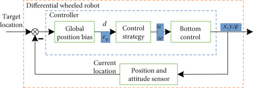
Figure 2 shows the basic process of the robot position control. The robot relies on the sensor to obtain the distance and angle information, and the controller relies on these two values to get the linear and angular velocities. Subsequently, the execution agency controlled the wheels to rotate according to the speed instruction to complete the movement.
Remark 1. It is noteworthy that when k = 0, eψ = α − ψ, which becomes the case of the study in [9]. In [9], the controller adjusts the robot’s yaw angle by driving α − ψ⟶0 (i.e., eψ⟶0). However, this method makes the robot’s yaw angle at the endpoint uncontrollable. With regard to function ((6)) proposed in this paper, we have when eψ⟶0. Therefore, by designing the u to drive α⟶0 and ψ⟶0, we can ensure that the yaw angle of the DWR remains ψ = 0 when the target position is reached.
- (1)
This method is applicable to practical engineering and has practicality. This is because after using the Euler system, the positioning control can become a linear system, making it easy to adjust convergence properties. Therefore, many recent excellent achievements in DWR positioning control are also using this method, such as [9]
- (2)
In engineering, we can theoretically avoid singularity by switching the control to lead out the origin, such as controlling the speed to 0 when the distance is less than 1 cm or less. Therefore, this method has good application value in engineering
3. Prescribed-Time Fractional Order Position Controller Design
Firstly, a novel constraint function is proposed based on existing orientation errors to optimize the correlation between the robot linear velocity and angle. Subsequently, a novel time-varying scale function is proposed based on the conventional PTC method, and the DWR’s prescribed-time fractional order control laws are formulated.
3.1. System Transformation and Objective
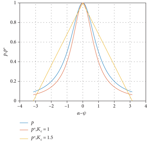
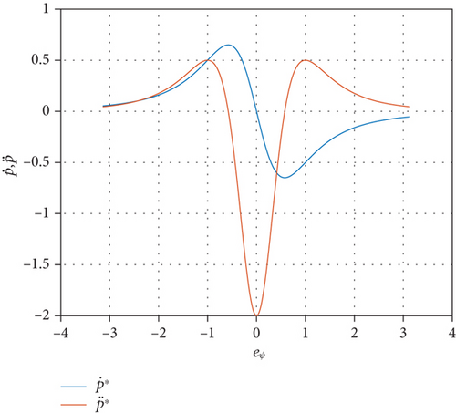
Obviously, the partial derivative of p(z) is discontinuous at z = 0, while p∗(z) has the characteristic of a continuous partial derivative. Therefore, using p∗ to replace p in the existing velocity control law can make the control action of the controller smoother.
Remark 2. Compared with [9], the new constraint function (10) satisfies p∗ > 0. When applied to the controller of DWR, the linear velocity is kept at zero only when the distance is zero, which can avoid the risk of misaligned control system balance points. Moreover, function (14) can slowly increase the linear velocity of the robot when the angle error is significant. Then, function (10) has better smoothness, which allows the robot’s trajectory to be further optimized.
3.2. Prescribed-Time Fractional Order Position Controller
Lemma 3 (see [16].)Consider the function
Corollary 4. Consider Lemma 3; if ξ(t) ≡ 0, then . That is, in the absence of disturbance ξ(t), the differentiable function V(t) is prescribed-time stable in T.
Remark 5. In the actual navigation process of the DWR, the distance d and orientation error eψ can be obtained through simple measurement of the sensor. Therefore, the initial distance d0 and the initial azimuth eψ0 are considered to be known a priori. Compared with [16, 17], the novel time-varying scaling function (17) effectively avoids the singularity problem of the traditional PTC and extends the effective time of the scaling function to t ∈ [t0, t0 + Tcon).
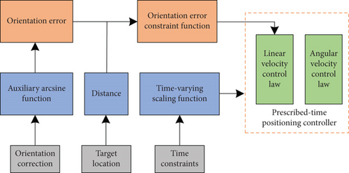
Generally speaking, the two-wheel speed of DWR does not require a state estimator to estimate the position but can be directly obtained through an encoder or Hall sensor. From this, the forward speed and angular velocity in the current state can be directly obtained. The acquisition of position and angle information can also be directly achieved by sensors without the need for further research. In engineering, if the acquisition of these quantities is unstable, some filtering methods can be used for estimation. However, these estimation algorithms are generally built-in to the sensor or independent of the control methods studied in this paper and can be directly integrated with the methods in this paper. Therefore, this paper will not study this issue here.
4. Stability Analysis and Parameter Choosing
In this section, the stability of the proposed controller is analyzed, and recommendations for the selection of adjustable parameters are given.
4.1. Stability Analysis
Before proceeding with the stability analysis, we first introduce the following lemma.
Lemma 6 (see [22].)Let x, y > 0 and γ > 0. Then,
We use this lemma to simplify the proof process of the control system stability. Second, we give the following theorem.
Theorem 7. The kinematic system (8) is stable for a prescribed time under the action of the control laws (16) and (18). Moreover, the convergence time of the system (8) can be determined by the prescribed-time parameter Tcon.
Proof. Choose the following Lyapunov function
Now, taking the time derivative of (21), we get
Substituting the auxiliary function Δ, and −0.4 ≤ Δζ ≤ 0.4, we can obtain
We substitute the proposed control laws (16) and (18) into the above equation to obtain
We have defined the minimum value of p∗ as ,
Subsequently, according to Lemma 6, we zoom in on the right half of inequality (25).
We solve the differential inequality (27) for the case when time t ∈ [0, tv].
From inequality (27), the Lyapunov function L is monotonically decreasing, which implies that the function L1−β is also monotonically decreasing. Therefore, when t⟶∞, there must exist some time tl such that L1−β(tl)⟶0. We can get
From equation (17), tl = tv. Therefore, for the Lyapunov function (21), there is . This means that when t⟶tv, there is d, eψ⟶0, i.e., . Then, when t > tw, we have d, eψ = 0.
In summary, the control laws (16) and (18) allow the control system (8) of the DWR to be asymptotically stabilized for a set time tv. This time tv is prespecified by the prescribed-time parameter Tcon. The proof is completed.
Theorem 7 proves that the system position error converges to 0 within the preset time, which means that the method in this paper achieves the preset time positioning control. Then, robots sometimes need to perform angle control. Therefore, this paper further proves that after the system is stable, the angle can also be stabilized.
Theorem 8. For the state variable ψ (yaw angle) in system (1), it is prescribed-time stable under the action of the control laws (16) and (18).
Proof. Choose the following auxiliary function Lα = α2/2. Taking its time derivative, we get
In Theorem 7, we conclude that |eψ| decreases gradually to zero at tv and remains stable after time tv. Therefore, when t⟶tv, there is
Remark 9. Due to the infinite gain risk, conventional PTC methods cannot be directly applied to DWR control systems that require continuous operation [16, 17]. In this paper, a novel time-varying scaling function (17) is designed and used to propose the prescribed-time fractional order position control laws (16) and (18). The proposed controller ensures that the kinematic system of the DWR (8) is prescribed-time globally asymptotically stable in tv. Then, tv is predetermined by a prescribed-time parameter Tcon. This issue ensures that the settling time for the closed-loop system stability is earlier than that of conventional preset time control methods.
The proposed velocity control laws (16) and (18) have the following advantages: (1) Compared with [9], the improved orientation error (6) allows the DWR to reach the target position with its yaw angle remaining at zero. Moreover, the novel orientation error auxiliary function (10) solves the problem that the robot cannot accelerate when the robot yaw angle is opposite to the azimuth angle (|α − ψ| = ±π). (2) In contrast to [20], the time-varying scaling function (17) ensures that the DWR’s control system is prescribed-time globally asymptotically stable at time tv, rather than a neighborhood around time tv.
4.2. Parameter Choosing
The prescribed-time parameter Tcon is satisfying 0 < d0/umax < Tcon (umax is the maximum line speed allowed for the robot) and is irrelevant to initial system conditions. K0 = 0.1 is given in literature [9]. Table 1 gives the selection range of controller parameters. To adjust the orientation error, we choose a small parameter k. This is because a large k may cause the robot to rotate too fast and lose accuracy. In the range of less than 1, the smaller parameter β theoretically is, the faster the system stabilizes. But at the same time, it will also cause the smoothness of the control law to deteriorate, which will actually affect performance. Therefore, this paper suggests that the selection of beta should be as large as possible, with a range of 1/2 < β < 1. According to the above statement, the time-varying scale function parameters need to satisfy K = min{0.6K1, K2}. On the basis of meeting the algorithm requirements, the parameter Tcon can be selected according to the actual situation. Therefore, the selection of parameters is summarized in this paper as follows.
5. Numerical Simulation
In this section, we used MATLAB to simulate the method mentioned and discussed the results. We first verified the effectiveness of the proposed controller. Subsequently, we compared the approach of this paper with literatures [9, 23], respectively. First, the effectiveness of control laws (16) and (18) is verified in the numerical simulation in Figures 5 and 6.
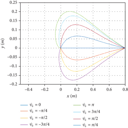
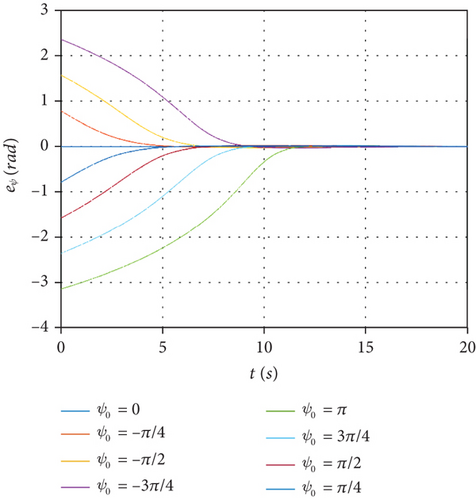
The initial position of the selected robot is (0, 0), and the target position is (0.8, 0). The remaining controller parameters are as follows: K1 = 2, K2 = 10, K = 1.2, Ke = 1, Tcon = 20, β = 24/25, k = 1/(2π). Testing a number of representative initial yaw angles (ψ0 = 0, −π/4, −π/2, −3π/4, π, 3π/4, π/2, π/4), Figure 5(a) shows the changes in the coordinates of the robot during position control, and Figure 5(b) shows the changes in the orientation error of the robot during position control. The simulation results show that under any initial yaw angle, the proposed control laws (16) and (18) can enable the robot to reach the endpoint in a prescribed-time Tcon. When |α − ψ| = π (p = 0), the line velocity in literature [9] is zero, causing error balance points, which may cause the robot not to move correctly. The linear velocity constraint function p∗ > 0 proposed in this paper avoids this risk.
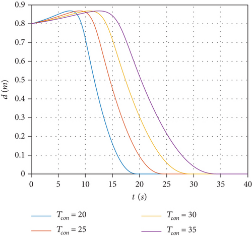
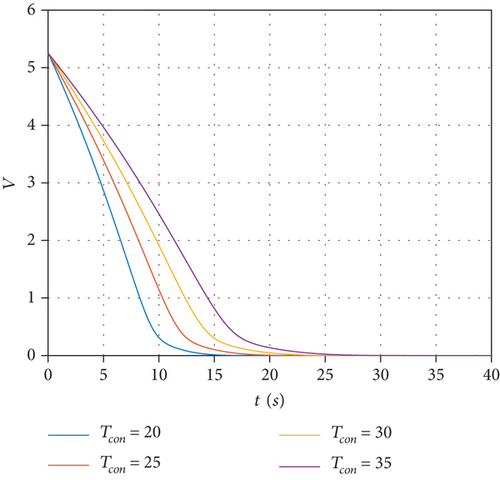
Subsequently, in Figure 6, set the initial value of the robot’s yaw angle to ψ0 = π. Figures 6(a) and 6(b) show the effects of different prescribed-time parameters (Tcon = 20, 25, 30, and 35) on the distance d and the Lyapunov function (21), respectively. The simulation results show that the designed position control law can control the time of robot arrival at the target position by adjusting Tcon, and the choice of Tcon is independent of other design parameters.
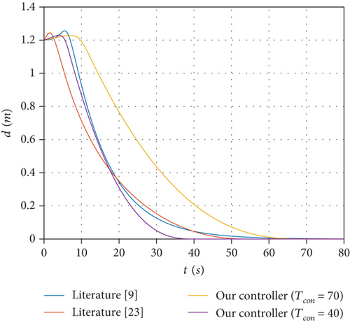
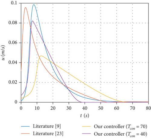
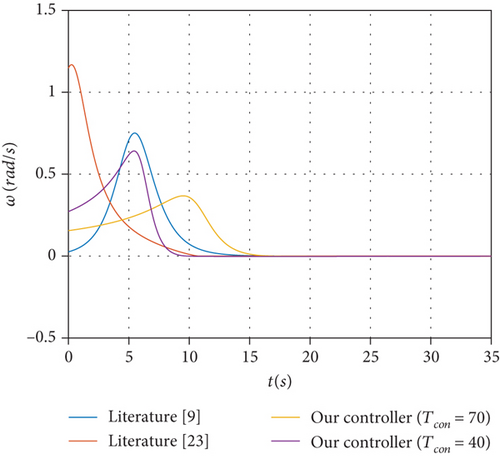
Finally, under the same driving conditions, we compare the asymptotically stable control laws in [9], the fixed-time control law in [23], and the control law of this paper. The initial position is fixed to (−0.4,0), the initial yaw angle ψ0 = −178°, and the target position is (0.8, 0). In literature [9], the control system of the robot reaches a steady state at around t = 70 s. Therefore, we set the prescribed-time parameter Tcon = 70 as a way to compare the advantages and disadvantages of the control strategies. Other parameters are as follows: K0 = 0.1, K1 = 2.5, K2 = 40, K = 1.2, Ke = 1, β = 24/25, and k = 1/(2π).
Figure 7(a) shows the variation in the distance between the robot and the target position. Although the controller in this paper has no significant advantage in the control effect of distance d, the controller proposed in this paper can adjust the time for the robot to reach the target position by setting the prescribed-time parameter Tcon, which is not available in other control methods. Figure 7(b) shows the comparison of linear velocity. The results show that the peak linear velocity under the control method of this paper is the lowest for similar settling times. Moreover, Figure 7(c) shows the comparison result of the angular velocity. Due to the fixed time control law of literature [23], there is a high power item with hidden dangers of high control gain, which makes its initial angle speed value significantly higher than other curves. In contrast, this paper’s angular velocity control law does not have a high power term and can achieve system convergence within a prescribed time.
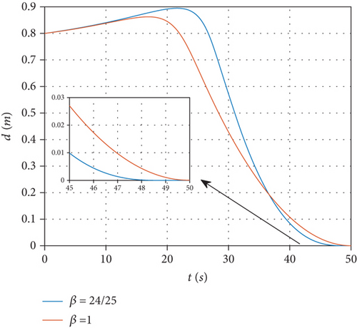
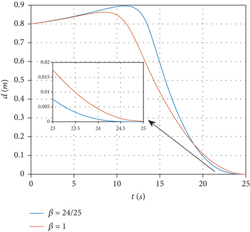
To illustrate the role of fractional order control, this paper presents a comparison between control laws with fractional powers and conventional prescribed-time controls. Figures 8(a) and 8(b) respectively show the cases where the prescribed settling times Tcon = 25 and 50. In order to improve the smoothness of the control law, this paper chooses the fractional power parameter beta = 24/25. The two figures illustrate that compared to the conventional prescribed settling time method, this method can ensure system convergence by using fractional powers before the preset deadline Tcon, thereby avoiding the risk of the term 1/(Tcon − t) being infinite at the prescribed settling time.
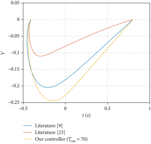
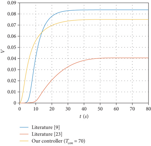
As shown in Figures 9(a) and 9(b), as regards the robot’s arrival at the target position, the control law proposed in this paper has the best trajectory and lower energy consumption.
6. Conclusion
This paper proposes a novel prescribed-time fractional order position controller for the DWR kinematic model. This controller is equipped with a new piecewise time-varying scaling function, which avoids the infinite gain risk faced near the settling time in conventional PTC. Using this controller, the system state of DWR can converge to a bounded interval in a prescribed time, and the prescribed time can be arbitrarily specified within the allowable physical range. Compared with reference [9], the designed linear velocity control law avoids the risk of incorrect balance points. In addition, when implementing position control, the proposed controller has a better movement trajectory and less energy consumption.
Using active disturbance rejection control to compensate for unknown disturbances to the robot is a good solution [24]. Also, when the robot has an actuator failure, DWR’s prescribed-time position control will be more complex [18]. In addition, considering combining adaptive control and prescribed-time control is also a topic worth researching [25, 26].
Conflicts of Interest
The authors declare that the research was conducted in the absence of any commercial or financial relationships that could be construed as a potential conflict of interest.
Acknowledgments
This work was supported by the Natural Science Foundation of Huzhou under grant 2022YZ31, the Huzhou Key Laboratory of Intelligent Sensing and Optimal Control for Industrial Systems under grant 2022-17, the Postgraduate Research and Innovation Project of Huzhou University under grant 2022KYCX58, the Zhejiang Province New Young Talent Plan Project in 2022 under grant 2022R431B021, and the Scientific Research Fund of Zhejiang Provincial Department of Education under the Grant Y202250212.
Open Research
Data Availability
The data is available from the corresponding author upon request. This paper uses MATLAB Simulink for simulation verification.


