High Gain Millimeter-Wave Transmitarray Antenna Based on Asymmetric U-Shaped Metasurface Using Characteristic Mode Analysis
Abstract
An asymmetric U-shaped millimeter-wave (MMW) metasurface (MS) transmitarray (TA) antenna is proposed based on characteristic mode analysis (CMA). The CMA of U-type unit shows two modes in the required frequency band and excites these two modes with a certain phase difference, so that the transmittance of the unit in the working band is greater than 0.8. The difference of lens unit is 360° by controlling the size change of the unit, and the transmission array is designed according to the phase distribution of the array. Through optimization simulation, the total size of the lens is 92.4 × 92.4 mm2, composed of 21 × 21 components and focal ratio of 0.85. The feed source is a SIW antenna, and then, the MS converts the quasispherical wave emitted from this feed source into a plane wave. The measured results show that the peak gain at 28 GHz is 22.3 dBi, the gain bandwidth at 3 dB is 5.8°, and the radiation efficiency is 81.6%. Due to the high gain and low-cost design, the proposed MS transmitarray antenna is suitable for MMW communication.
1. Introduction
With the development of wireless communication technology, high-speed and low latency wireless networks are needed in many scenarios [1, 2]. The millimeter-wave (MMW) band has a higher data transmission rate; thus, it is widely used. 5G MMW applications need high gain antennas to compensate for transmission loss for a better signal-to-noise ratio, so it puts higher requirements on MMW antennas. An MMW lens composed of a subwavelength metasurface (MS) array provides a new solution idea to improve antenna performance.
MS antennas are microwave applications that utilize the unique electromagnetic properties of two-dimensional metamaterial structures for radiation, and these structures improve the performance of the antenna by manipulating electromagnetic waves. MS has been widely used in applications such as reflective antenna arrays, scattering reduction [3], frequency-selective surface (FSS) [4], and massive multiple-input multiple-output (MIMO) antennas [5], and in particular, the MS can be used as a planar lens to convert the incident planar wavefront into a spherical wavefront with a specific phase distribution on the MS to achieve electromagnetic wave variations. In reference [6], coded MS is combined with traditional antenna to effectively reduce scattering while maintaining high gain. A new compact transmission-coded MS lens is proposed in reference [7], which achieves high gain and multibeam effects by using different arrangement of elements. Phase gradient distribution is a new type of antenna array designed based on generalized Snell’s law, which can realize vortex wave or deflect electromagnetic wave, etc. Beam focusing is one of its most basic applications [8, 9]. For the design of MS lens, the most commonly used method is to use multilayer media to achieve sufficient phase accumulation. Reference [10] proposed a 4-layer resolution near-field focusing MS lens to achieve the acquisition of high-frequency gain antenna. Alibakhshikenari et al. and Gao et al. proposed an MS lens for MMW MIMO applications with a lens consisting of two dielectric substrates and a certain air gap in between, resulting in a large antenna size [11, 12]. Although multilayer methods have good characteristics, they are not the best solution for compact and lightweight microwave devices, and they have limitations in manufacturing.
In addition, the design of antennas with scattering parameters of incident plane waves is often complicated, and the problem of miniaturization has not been solved, and we try to find a simple method to design MS lenses with a single-layer structure. In the characteristic mode analysis (CMA) for different conductors, the surface can be decomposed into a series of mutually independent mode currents that are independent of other conditions (e.g., feed position) and only related to the properties of the conductor itself (e.g., size and shape), which provides accurate analysis and allows us to visualize the resonant characteristics of the antenna [13, 14]. Based on CMA, the reference [15] proposed a method consisting of circular waveguide-fed single-layer metamaterial lens antenna consisting of 12 capacitive coupled elements distributed along a ring. In reference [16], a dual-polarized double-layer MS lens based on split dipole unit cells is proposed, but its addition of copper vias in the middle of the dielectric substrate board increases the design cost.
In this article, a CMA of a via-free symmetric U-shaped MMW MS lens antenna is proposed. It is printed on both sides of a dielectric substrate without an overvias, which makes the fabrication easier and less costly. CMA of the U-shaped unit cell shows two modes in the desired frequency band. By exciting these two modes with a certain phase difference, the transmittance of the unit cell remains above 0.8 in the operating band while the phase range covers 360°. The total dimensions of the lens are 92.4 × 92.4 mm2, consisting of 21 × 21 elements with a thickness of 0.142λ0, where λ0 is the free-space wavelength at the operating frequency (28 GHz). All simulations were performed using the commercial software Computer Simulation Technology (CST) Microwave Studio. The antenna has certain application value in millimeter-wave communication system.
2. Design of Element of Transmission Array
2.1. CMA of the Unit Cell of the Transmitarray
The unit cell of the U-shaped lens is shown in Figure 1. The unit cell has a period p that of 4.4 mm and consists of two symmetrical pairs of U-shaped metal layers on the dielectric substrate at the top (yellow) and bottom (blue), with the top and bottom metal layers symmetrical about the origin center in the top view plane. The dielectric substrate is Rogers RO4003C with dielectric constant εr = 3.55, loss angle tangent tan δ = 0.0027, and thickness h1 = 1.524 mm. The material has low transmission loss and is suitable for use in the MMW band. For the CMA simulation, the substrate is set to ideal lossless, and port2 is set to plane wave excitation.
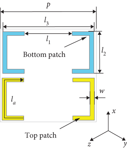
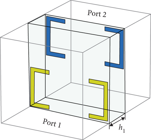
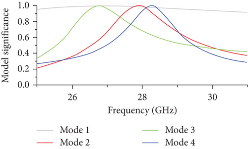
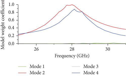
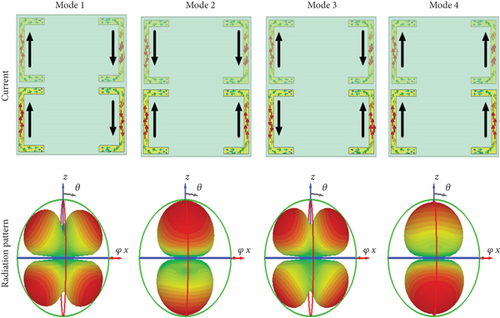
Figure 2 shows the MS of the unit cell as a function of frequency. Four significant modes are observed in the frequency band with a resonant frequency of 28 GHz. The corresponding mode currents and radiation direction plots are shown in Figure 3(a). Modes 2 and 4 have the same layer U-current direction, while modes 1 and 3 have the opposite same layer U-current direction. When an incident plane wave is vertical, only the same current direction can be effectively excited, and the other modes have a hole in the center of their radiation direction diagram due to the reverse current and cannot be excited by the vertically incident electromagnetic wave. The modal weighting coefficient (MWC) is shown in Figure 2(b), further verifying that modes 2 and 4 can be effectively excited and modes 1 and 3 cannot be excited.
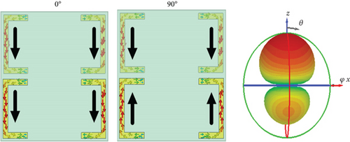
Modal currents of modes 2 and 4 have a phase difference of 90°, while the excitation of modes 2 and 4 can achieve the combination of modes. As shown in Figure 3 for the mode current and radiation direction diagram after the combination of modes 2 and 4, the top and bottom mode currents are in the same direction at 0° phase for electric resonance and reverse at 90° phase when the top and bottom layers form a toroidal current for magnetic resonance, and the alternating evolution of mode currents in time constitutes a magnetic dipole that induces a surface magnetic current. When the equilibrium conditions between surface currents and induced magnetic currents are satisfied, resonance is induced, and thus, electromagnetic waves are radiated. The combined mode directional map is more symmetrical and has lower reflections compared to the individual modes.
2.2. Electromagnetic Characteristics of Transmission Element
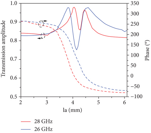
The transmission characteristics of the unit cell are simulated with the electromagnetic simulation software CST, and the boundary conditions are set to periodic boundaries. The simulation results of transmission phase and amplitude are shown in Figure 4. The total length la of the U-shape is a variable, and the amplitude and phase are controlled by changing its magnitude. When la changes from 2 mm to 6.1 mm, the phase change can cover 360° and the transmission amplitude is greater than 0.8. Due to the symmetry of the structure, it has good transmission performance and can meet the requirements of the focused MS lens design. The structure parameters at the highest transmission are as follows: w = 0.2 mm, p = 4.4 mm, l1 = 2.2 mm, l2 = 2 mm, and l3 = 4.2 mm.
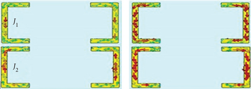
To observe the frequency response of the unit cell, its surface current at 28 GHz is simulated. When the unit cell is excited by an x-polarized electromagnetic wave from the port, the surface currents are induced in two layers, denoted as J1 and J2, respectively; as can be seen in Figure 5, J1 and J2 have opposite flow directions. The results show that the surface currents on the two layers with opposite directions form a current loop with the potential shift vector, resulting in an orthogonal magnetic field, and the results obtained are consistent with those of the CMA.
3. Design of Transmission Array and the Feed Antenna
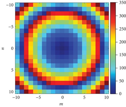
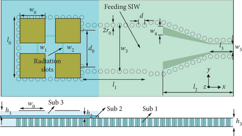
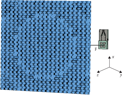
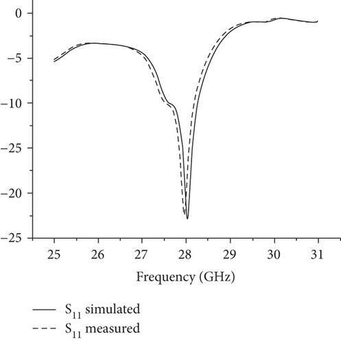
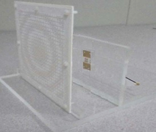
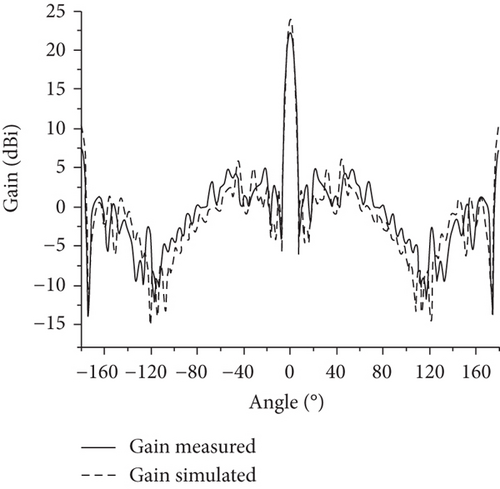
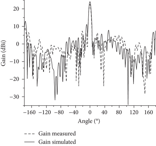
An MS lens using 21 × 21 unit cells was created at 28 GHz, as shown in Figure 7. Figure 7(a) is the structure diagram of the feed antenna. The substrate material of the upper and lower media of the feed antenna is Rogers RO4003C, whose dielectric constant is 3.55 and tangent loss is 0.0027. The substrate of the middle layer is Rogers RO4450B, whose dielectric constant is 3.54 and tangent loss is 0.004. Figure 7(b) shows the overall structure of the antenna array. The simulated and measured return loss of the feed antenna is shown in Figure 8; the passband is between 27.4 GHz and 28.5 GHz. The distance between the feed antenna and the array is F = 78.8 mm. The experimental setup is shown in Figure 9. The radiation patterns in the E- and H-planes are shown in Figure 10. The transmitarray antenna has 3 dB gain bandwidth of 5.8° and 5.5° in the E-plane and H-plane, respectively.
4. Discussion of Results
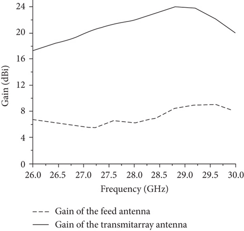
The proposed transmitarray is feed SIW antenna at 78.8 mm from the transmitarray, and it can be found that the electric field gathers energy at the focal point and the gain increases to 22.3 dBi. It proves that the designed array has a good focusing effect on electromagnetic waves. As shown in Figure 9, the 3 dB beam widths are 5.8° and 5.5° in the E- and H-planes at 28 GHz. The sidelobe levels (SLL) are -16.7 dB and -14.7 dB at 28 GHz. As shown in Figure 11, the realized gain of transmission array is increased from 6.2 dBi to 22.3 dBi at 28 GHz. The comparison of the proposed MS lens with referenced designs is shown in Table 1. The transmission array antenna has significant advantages in gain improvement and efficiency.
| Ref. | Frequency (GHz) | F/D ratio | Num. of layers/unit | Peak gain (dBi) | Antenna efficiency |
|---|---|---|---|---|---|
| 9 | 10 | 0.19 | 4/13 × 13 | 18.5 | — |
| 17 | 28 | 0.5 | 4/21 × 21 | 11.53 | 0.481 |
| 18 | 28 | 0.2 | 4/15 × 15 | 20.2 | 0.541 |
| 16 | 10 | 0.875 | 4/25 × 25 | 17.85 | — |
| This work | 28 | 0.85 | 2/21 × 21 | 22.3 | 0.816 |
5. Conclusion
An asymmetric U-shaped double-layer MS transmitarray antenna based on CMA is proposed. The results show that the reflected electromagnetic waves can be effectively eliminated by exciting two main modes in the desired MMW frequency range. It is printed on both sides of a dielectric substrate without an overhole, which makes fabrication easier and less costly. The proposed antenna operates at 28 GHz, and the MS transmitarray consists of 21 × 21 elements. Simulation and experimental results demonstrate that the antenna exhibits good performance based on the asymmetric U-shaped double-layer transmitarray. Due to the high antenna efficiency and low-cost design, the proposed MS transmitarray can be of great use in MMW communication systems.
Conflicts of Interest
The authors declare that they have no conflicts of interest.
Acknowledgments
This work was funded by the Graduate Innovation Program of the China University of Mining and Technology under grant 2022WLJCRCZL107.
Open Research
Data Availability
The data that support the findings of this study are available from the corresponding author upon reasonable request.


