Sum Rate Optimization for MIMO Multicasting Network with Active IRS
Abstract
This paper considers a multiple-input multiple-output (MIMO) multicasting system aided by the intelligent reflecting surface (IRS). We aim to maximize the sum information rate via jointly designing the transmit precoding matrix and the reflecting coefficient (RC) matrix, subject to the transmit power constrains of the Tx and IRS. To tackle the nonconvex problem, we recast the original problem into an equivalent formulation by using some important facts about matrices and proposed a block coordinate descent (BCD) method to optimize the variables. Finally, simulation results validate the effectiveness of active IRS in enhancing the rate performance.
1. Introduction
Recently, intelligent reflecting surface (IRS) has been proposed as an effective approach for wireless communication. An IRS is a metasurface consisting of several programmable elements that can be smartly controlled to manipulate wireless propagation environment [1]. Since passive IRS only reflects incident signals, the power consumption is relatively much smaller than that of traditional active transmitter [2]. For example, IRS-assisted scheme has been investigated in the millimeter-wave (mmWave) networks [3], the antijamming communication networks [4], the simultaneous wireless information and power transfer (SWIPT) networks [5], the unmanned aerial vehicle (UAV) networks [6], the hybrid satellite-terrestrial networks [7], etc. Besides, some novel IRS structures have been proposed, such as the multilayer IRS [8] and the simultaneous transmission and reflection intelligent surface [9]. More and more research suggests the promising application prospect of IRS. However, to overcome the severe double path loss in the reflecting channel, the literature recently introduced a novel active IRS architecture [10], in which each element is integrated with an amplifier [11]. By converting direct current bias power into radio frequency power, the active element can directly amplify the incident signal [12]. Recently, the energy efficiency of active IRS has been studied [13], and the results suggested that active IRS can obtain higher energy efficiency than passive IRS. Then, the literature investigated the active IRS-assisted secure transmission [14] and extends to the spectral and energy efficiency tradeoff of active IRS-assisted network [15]. While the literature indicates that active IRS can obtain higher energy efficiency than passive IRS in multiuser multiple-input single-output (MISO) network [16], recently, the authors studied the beamformer design in active IRS-assisted multiuser multiple-input multiple-output (MIMO) radio networks [17], where a sum mean squared error (MSE) objective was optimized. And the authors investigated the secrecy beamformer in active IRS-assisted wiretap channel with energy harvesting [18], where a max–min fairness problem was addressed by the successive convex approximation algorithm.
- (i)
We consider a multiuser MIMO multicasting network, where both the direct link and the cascaded link are existing. Then, to overcome the main system bottleneck in the passive IRS-aided network incurred by the double fading effect, we propose to use active IRS to amplify and alter the phase of the incident signal, thus improving the spectral efficiency of this network
- (ii)
Specifically, we aim to maximize the sum information rate of these users, by jointly designing the precoding matrix at the Tx and the reflecting coefficient (RC) at the IRS. The formulated problem is nonconvex, mainly due to the coupled variables and the complicated logarithmic determinant functions. To handle this obstacle, we reformulate the sum rate maximization problem as an equivalent problem by using some important facts about matrices, where the objective is linearized. Then, a block coordinate descent (BCD) algorithm is developed to handle the reformulated problem, where the subproblems are solved alternatingly until convergence. In fact, several subproblems have closed-form solutions, and the others can be solved by the quadratically constrained quadratic program (QCQP). Thus, the proposed algorithm has polynomial time computational complexity
- (iii)
Finally, simulation results verify the effectiveness of the proposed algorithm as well as the superiority of active IRS when compared with other benchmarks. Besides, some meaningful insights can be attained: (1) active IRS can effectively alleviate the double fading attenuation than passive IRS; (2) it is beneficial to design the RC properly, since random RC suffers from certain performance loss; (3) it is better to deploy the active IRS close to the users than Tx to improve the sum rate performance
1.1. Notations
The conjugate, transpose, conjugate transpose, and trace of matrix A are denoted as A†, AT, AH, and Tr(A), respectively. a = vec(A) denotes to stack the columns of matrix A into a vector a. A≽0 indicates that A is a positive semidefinite matrix. ⊙ and ⊗ denote the element-wise product and the Kronecker product, respectively. Diag(a1, ⋯, aM) represents a diagonal matrix with a1, ⋯, aM on the main diagonal. denotes the real part. denotes a circularly symmetric complex Gaussian random vector with mean 0 and covariance A.
2. System Model and Problem Formulation
2.1. System Model
As shown in Figure 1, the MIMO system consists of one Tx, one IRS, and K users. It is assumed that the Tx and the k-th user have Nt and Nk antennas, while the IRS has M elements, respectively. We denote , , and as the channel coefficient from the Tx to the k-th user, the Tx to the IRS, and the IRS to the k-th user, respectively.
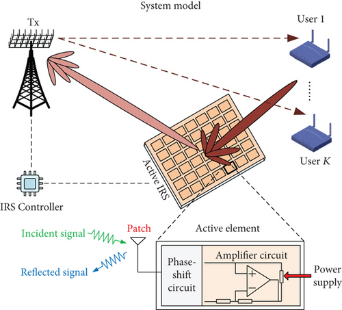
Since active IRS only utilizes power amplifiers and phase-shift circuits that control and reflect the signals, no dedicated digital-to-analog converters (DACs), analog-to-digital converters (ADCs), and mixers are required. In contrast, relays are usually equipped with these mentioned electronic components for transmission and low-noise amplifiers for reception, which leads to higher hardware cost and power consumption than active IRS [19].
In this paper, all CSI is assumed perfectly obtained at the Tx, which is due to the fact that several channel estimation techniques have been investigated for obtaining the CSI such as the progressive refinement method [20] and the parallel factor decomposition method [21], which makes the estimation and acquirement of the CSI become practical. In addition, there exists an IRS controller which coordinates the CSI exchange between the Tx and the IRS [22], thus achieving the joint design.
Without loss of generality (W.l.o.g), we assume that and sk, si are independent for ∀i ≠ k.
In addition, and denote the additive noise at the IRS and the k-th user, respectively.
2.2. Problem Statement
The main difficulties in solving ((4a)–(4d)) are twofold: firstly, (4a) is nonconvex; secondly, the variables are highly coupled.
3. The Joint Precoder and RC Design
To tackle the difficulty of (4a), we extend the key idea of the popular weighted mean square error minimization (WMMSE) algorithm [27], to reformulate ((4a)–(4d)), and then use the BCD method [28]. We first introduce the following lemmas.
Lemma 1 (see [28].)Define matrix function
Equation 1: for any positive definite matrix P ∈ ℂm×m,
Equation 2: for any positive definite matrix Q, we have
Equation 3: we have
For more detailed derivation about these equations, reader can refer to [29, 30].
3.1. Reformulation of the Objective (4a)
((12a)–(12d)) is still hard to solve due to the coupled variables. However, when several variables are fixed, ((12a)–(12d)) can be turned into convex problem with respect to (w.r.t) the other variables, thus motivating us to propose the BCD algorithm.
3.2. The BCD Algorithm
- (A)
Subproblem 1: optimizing {Uk, Ψk} with given {Wk, Θ}
- (B)
Subproblem 2: optimizing Wk with given {Θ, Uk, Ψk}
- (C)
Subproblem 3: optimizing Θ with given {Wk, Uk, Ψk}
Then, we turn ((18a)–(18c)) into an equivalent problem w.r.t . Firstly, we introduce the following lemma.
Lemma 2 (see [33].)Let C1 ∈ ℂm×m and C2 ∈ ℂm×m be matrices, and 1 = [1, ⋯,1]T is a m × 1 vector. Assuming that E ∈ ℂm×m is a diagonal matrix E = diag(e1, ⋯, e2) and e = E1, then we have
((23a)–(23c)) is also a QCQP problem, which can be solved by CVX.
3.3. Summarization and Discussion
The whole BCD algorithm is summarized in Algorithm 1.
-
Algorithm 1: The BCD algorithm.
-
1:Initialization: Set a feasible point {Wk, Θ} and i = 0.
-
2:repeat:
-
d) Update {Uk, Ψk, Wk, Θ}.
-
e) i⟵i + 1.
-
3:until Converge
-
4: Output .
Here, we analyze the computational complexity of Algorithm 1. In fact, the main complexities of Algorithm 1 lie in the subproblems ((15a)–(15c)) and ((23b)–(23c)). Besides, the complexity for solving a QCQP problem is given by , where m denotes the number of variables, n denoted the number of constraints, and ϵ is the solution accuracy [34]. Thus, the complexities of ((15a)–(15c)) and ((23b)–(23c)) are given by and , respectively.
In addition, the convergence of Algorithm 1 has been analyzed [29]; thus, we omit the details for brevity.
4. Simulation Results
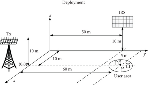
The deployment is given in Figure 2, where there exists one Tx, one IRS, and 3 users. The coordinates of Tx and IRS are (0m, 0m, 10m) and (10m, 50m, 10m), while the users are randomly located in a circle with radius 5m and centered at (0m, 60m, 1.5m), respectively [5].
Unless specified, we set Ps = 30 dBm, Pr = 30 dBm, Nt = 8, M = 40 [15], Nk = 2, and [17]. The large-scale path is denoted as , with L0 denoting the channel gain at d0 = 1, and β is the path loss exponents. In addition, we assume that the Tx-user link follows the Rician fading with Rician factor 5 with β = −4, the Tx-IRS link follows the Rician fading with Rician factor 3 with β = −2.8 [16], and the IRS-user link follows the Rayleigh fading with β = −2.2 [16, 17]. In addition, all the results are obtained by 200 numbers of channel realizations.
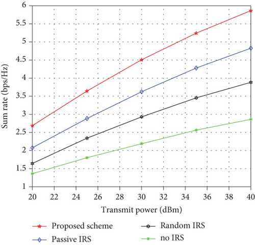
We compare the design with the following methods: (1) the passive IRS scheme 32, (2) the no IRS scheme, and (3) the random IRS scheme, e.g., choosing Θ randomly. These methods are labeled as “proposed design,” “passive IRS,” “no IRS,” and “random IRS,” respectively.
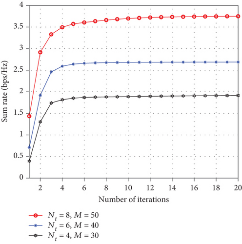
Firstly, we studied the convergence of the BCD method. Figure 3 shows Rs versus the number of iterations with different Nt and M. From this figure, we can see that for different Nt and M, Rs always increase with the iteration numbers and gradually converge within 20 iteration, which confirms the convergence of the BCD method.
Then, we show the sum rate versus Ps. From Figure 4, we can see that for all these schemes, Rs increase with Ps, and all IRS-aided schemes obtain better performance than the no IRS-aided designs. Besides, the active IRS scheme significantly outperforms the passive IRS design, mainly owing to the power amplification effect which alleviates the impact of double fading attenuation. Thus, the received signal power at the users is enhanced and Rs is improved.
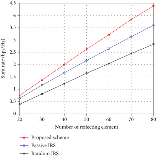
Next, in Figure 5, we show Rs versus M. From this figure, we can see that for all these IRS-aided methods, Rs tends to increase with the increase of M, since more signal can incident the IRS with larger M. In addition, the reflected signal at the IRS will increase with M when the RC is properly designed. However, when using random IRS, only array gain can be obtained, thus suffering from certain performance loss. This result further verifies that more Rs improvement can be achieved by using a larger IRS and optimizing the RC properly.
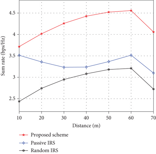
Last, Figure 6 plots Rs versus the Tx-IRS distances, where we assume that the IRS moves along the y-axis from the Tx to the user’s area. From this figure, we can see that the active IRS scheme always outperforms the passive IRS scheme in the considered region. Moreover, for active IRS, the Rs increases when IRS moves from the Tx to the user’s area, while for passive IRS, the Rs first decreases to a low point and then increases. Thus, deploying the active IRS near the users is beneficial to improve the Rs.
5. Conclusion
This work studied the active IRS-aided MIMO multicasting network, where the sum rate was maximized by jointly optimizing the precoder and RC, subject to the transmit power constraint at the Tx and IRS. We decouple the original problem into several subproblems and then proposed a BCD algorithm to optimize the variables. Simulation result verified the performance of the proposed design as well as the superiority of active IRS when compared with other benchmarks.
Conflicts of Interest
The author(s) declared no potential conflicts of interest with respect to the research, authorship, and/or publication of this article.
Acknowledgments
The author(s) disclosed receipt of the following financial support for the research, authorship, and/or publication of this article: this work was supported by the industry-university-research cooperation project of Jiangsu province under Grant No. BY2018282.
Open Research
Data Availability
Data are available on request.


