Effect of Reinforced Bucket on Bearing Capacity and Natural Frequency of Offshore Wind Turbines Using Pile–Bucket Foundation
Abstract
Large-diameter monopiles have been widely used for constructing offshore wind turbines. The bearing capacity of a monopile foundation is a significant research problem. In this study, a new type of foundation, known as the pile–bucket foundation, was investigated to improve the bearing capacity of monopiles. A finite element software was used for establishing several numerical models of monopile and pile–bucket foundations to analyze the reinforcement afforded by the bucket attached to the monopile foundation. Furthermore, considering that offshore wind turbines are prone to resonance under the excitation of wind and wave loads, the natural frequencies of the monopile and pile–bucket foundations were determined and compared using both analytical and numerical methods. The results show that compared to the monopile foundation, the pile–bucket foundation has a significantly higher bearing capacity, mainly for large bucket diameters. The natural frequencies of the pile–bucket foundations are slightly higher than those of the monopile foundations. The addition of the bucket can effectively improve the natural frequency without changing the diameter of the monopile and thus saving the foundation cost.
1. Introduction
With the increasing demand for green energy, the construction of wind farms has become widespread. Several types of foundations are used in offshore wind turbines, such as monopile, gravity, suction cylindrical, jacket, group pile, and floating foundations [1, 2]. Different types of foundations are suitable for structures subjected to different depths of water and soil properties. In some sea areas, such as the Zhejiang Sea area, the geological conditions are unfavorable, and deep clay layers exist. Hence, the diameters of monopiles in such areas need to be large to satisfy the critical requirements of foundation stiffness and natural frequency, and these monopiles should reach greater depths. However, large monopiles significantly increase the foundation costs.
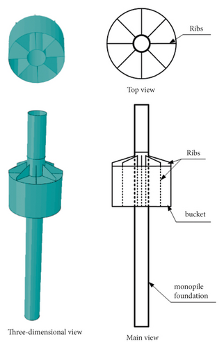
The large-diameter monopile is the most widely used type of foundation for offshore wind turbines because of its simple structure and low cost. Compared to monopile foundations, suction cylindrical foundations have the advantages of simple installation and good capsizing ability. Recently, researchers have proposed a new type of foundation known as the pile–bucket foundation, in which a bucket is attached to the monopile foundation. The construction of the pile–bucket foundation can effectively improve the load-bearing resistance of shallow soils and reduce construction costs. Ding et al. [3] and Zhu [4] compared monopile foundations and pile–bucket foundations comprising similar proportions of steel. Huang et al. [5] investigated the working mechanism of a pile–bucket foundation under vertical loads through numerical analyses and found that the pile–bucket foundation can be used to effectively reduce displacement and improve the bearing capacity of the foundation. Liu et al. [6] observed that the pile–bucket foundation showed a reasonable load transfer mode, in which the pile resisted almost all vertical loads and the bucket resisted horizontal loads. Liu et al. [7] used finite element software to analyze the bearing capacity of a pile–bucket foundation under a specific vertical displacement and demonstrated that the bucket diameter had a significant influence on the vertical bearing capacity of the structure. Thus, it can be inferred that previous investigations on the pile–bucket foundation were mainly limited to the vertical bearing capacity. Detailed studies on the p–y curves of the pile–bucket foundations under horizontal loads have not been reported.
In addition to the bearing capacity, the dynamic behavior of a structure is another critical issue that should be considered during the design stage. This behavior should be considered because structures are typically prone to resonance under the excitation of wind and wave loads, which can lead to a loss of service performance. The two frequencies that are most likely to induce resonance are as follows [8]: 1P frequency, which arises from the rotor, and NbP frequency, which is caused by the blade passing frequency owing to the shadow each time the blade passes over the tower. The value of NbP is usually 2P/3P. The first-order natural frequency of the structure should be kept away from the 1P and 2P/3P frequencies during the design stage in order to minimize resonance. Several studies have focused on determining the natural frequency of monopile foundations. Tempel et al. [9] and Reinhard et al. [10] reported that the foundation stiffness had a slight effect on the dynamic characteristics of structures while assuming that the bottom of the foundation was rigid and fixed. Zaaijer et al. [11] developed a simplified model for simulating foundations, but their proposed method for determining the foundation stiffness could not be used to obtain an exact solution. Bhattacharya et al. [12], Bhattacharya et al. [13], and Adhikari et al. [14] simplified the foundation as two springs with lateral stiffness and rotational stiffness, and they used an experimental measurement method to determine foundation stiffness. Based on these studies, Yu [15] considered the effect of coupling stiffness on the first-order natural frequency of structures. The foundation stiffness was calculated using a simplified method presented in the European standard code (European Standard, Eurocode 8, Part 5, 1998), but the simplified calculation method is only applicable to small-diameter piles. This simplification is inappropriate for large-diameter monopile foundations and pile–bucket foundations. Until recently, very few studies on the fundamental frequency analysis of pile–bucket foundations were reported. Guan et al. [16] used finite element software to model the upper and lower structures. The model analysis was performed to analyze the resonance frequencies of the structure with a pile–bucket foundation; however, the results were not compared with the measured value to verify the accuracy of the model.
In this study, three-dimensional finite element method (FEM) analysis models of monopile and pile–bucket foundations were established in ABAQUS to investigate the degree of improvement in the horizontal bearing capacity of a monopile foundation after attaching a bucket. The differences in their p–y curves were compared. In addition, the FEM–analysis combined method (i.e., the FEM combined with the analytical method) was proposed to obtain the natural frequency. The simulation results were compared with the experimental results to verify the accuracy of the model and the effect of the bucket on natural frequency.
2. Finite Element Modeling
The models developed in this study are based on an offshore wind farm located in the Pinghu Sea area of Hangzhou Bay, which covers an area of 48 km2 with a planned capacity of 300 MW. The center of the wind farm is approximately 20 km away from the sea, and the depth of water is 8–12 m. The topography of the seafloor around the site area varies slightly, and the maximum slope of the sea beach surface is less than 1°. Therefore, it is suitable to use the monopile foundation or pile–bucket foundation. The physical and mechanical properties of the soil were obtained experimentally (Table 1).
| Soil mass | Effective gravity, γ (kN/m3) | Elastic modulus, E (MPa) | Friction angle, φ (°) | Cohesion, c (kPa) | Poisson’s ratio, υ |
|---|---|---|---|---|---|
| Around the pile (the muddy clay) | 7.6 | 10 | 28.81 | 15 | 0.29 |
| Bottom of pile (the silty clay) | 8.2 | 20 | 35.75 | 8 | 0.32 |
In the monopile foundation model, the diameter of the pile was 6 m; the pile length was 50 m; and the pile length under the mud surface was 30 m. The thickness-diameter ratio of the pile was 1%, and the wall thickness was 6 cm. A monopile foundation with a diameter of 6 m was used as the reinforcement foundation when modeling the pile–bucket foundation. The bucket height (H) was selected as the pile diameter of one, two, and three times, and the bucket diameter (D) was selected as the pile diameter of three, four, and five times. The wall thickness was 2 cm. Table 2 lists the specific parameters.
| Model 1 | Model 2 | Model 3 | Model 4 | Model 5 | |
|---|---|---|---|---|---|
| D (m) | 18 | 24 | 24 | 24 | 30 |
| H (m) | 12 | 6 | 12 | 18 | 12 |
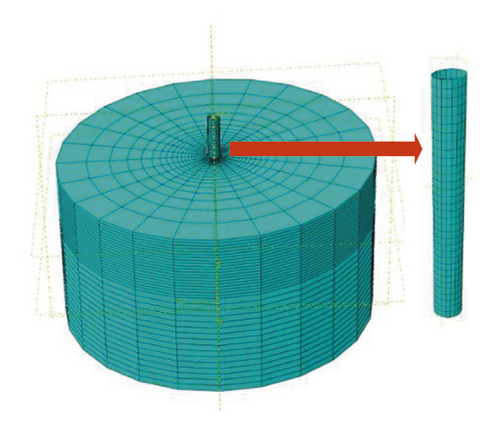
The diameter of the soil model is 150 m, which is 25 times the pile diameter as well as 5 to 8.33 times the bucket diameter for different bucket models. The boundary effect was neglected during the static analysis of the abovementioned model. Figure 1 shows the analysis model of the monopile foundation and that of the pile–bucket foundation.
3. Model Validation
For the analysis of the bearing capacity of a structure, the appropriate selection of a constitutive relation is crucial. It has been proven that the M–C constitutive model can be used to precisely describe the horizontal force behavior of the soil around piles. The pile-soil interaction consists of two parts, namely the contact interaction in the normal and tangent directions. The normal behavior of soil-pile interaction is modeled by “hard contact” in ABAQUS and the tangent behavior of soil-pile interaction is simulated by the friction coefficient.
The experimental model developed by Zhu et al. [17] and Zhu et al. [18] was simulated using the FEM to verify the feasibility of the M–C constitutive model. The centrifugal test model developed by Zhu et al. [17] and Zhu et al. [18] involved a monopile foundation with a pile diameter of 2.5 m. A secant modulus, E50, of 55 MPa was selected as the elastic modulus, E, of the numerical analysis model. Compared to the initial tangent modulus Eini, which only contained the elastic strain, the secant modulus E50 was more suitable to reflect the deformation of the large-diameter pile foundation model (Code for design of building foundation, 2011). The other model parameters are listed in Table 3.
| Pile diameter (m) | Wall thickness (mm) | Embedding depth (m) | Pile length (m) | Density (kg /m3) | Poisson’s ratio | Young’s modulus of steel (GPa) |
|---|---|---|---|---|---|---|
| 2.5 | 45 | 50 | 65 | 7.8 × 10³ | 0.3 | 210 |
The soil was modeled using a six-plane eight-node linear reduced integral element (C3D8R), and the four-node curved surface Table 4 shell (S4) was adopted as the pile element. The model diameter was 50 m, which was 20 times the pile diameter, and the model height was 75 m. Additionally, the end of the pile was at a distance of 10 times the pile diameter from the bottom of the model. The boundary effect was neglected in this model. A typical analysis model is depicted in Figure 2.
| Cohesion (kPa) | Peak friction angle (°) | Residual friction angle (°) | Dilatancy angle (°) | Effective gravity (kg/m3) | Poisson’s ratio |
|---|---|---|---|---|---|
| 0.5 | 37.7 | 34.8 | 2.9 | 9.45 | 0.21 |
Considering pile-soil interaction, the in situ stress balance in ABAQUS cannot converge even if the grid is relatively regular. Therefore, the following methods were adopted in this study. The first step involved performing an automatic in situ stress balance analysis where the pile and bucket were set to be invalid and the soil was balanced under the action of gravity. In the second step, a static analysis was conducted, where the pile and bucket were newly activated and the overlapping parts of the soil and the pile and bucket were assumed to be invalid. Additionally, the pile-soil interaction is activated. The third step involved the application of different horizontal loads on top of the pile and the determination of the deformation and internal force of the pile.
Figure 3 show a comparison of the deformation curve and bending moment distribution curve, respectively, obtained from Figure 4 centrifugal model test and the finite element analysis. Piles subjected to three different forces and featuring a loading height of 2.7 times the pile diameter were considered for this comparison. Figure 5 presents the comparison of the p–y curves obtained using the two methods.
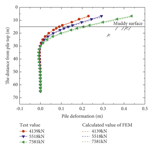
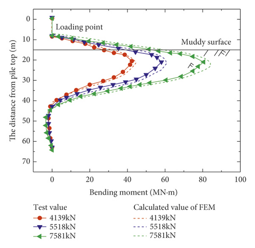
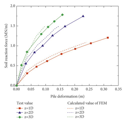
From Figures 3 and 4, it is evident that the results obtained using the two methods are generally consistent. Thus, the results obtained via the finite element numerical simulation were found to be similar to the experimental test results reported by Zhu et al. [17] and Zhu et al. [18], which implied that the M–C constitutive model reflected the horizontal deformation of the pile well.
4. Horizontal Bearing Capacity Analysis
Based on the verified three-dimensional numerical analysis model, the M–C constitutive model was used to simulate the pile-soil interaction. A monopile foundation model and five types of pile–bucket foundation models were established. The model parameters are discussed in Section 2, and the simulation process was consistent with that described in Section 3. In this model, five different loading forces were applied to the pile head. The finite element analysis results are presented as follows.
4.1. Comparison of Horizontal Displacements
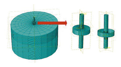
Figure 6 shows a comparison of the horizontal displacement for the pile and bucket in the reinforcement section of model 3 (D = 24 m and H = 12 m) under five different loading conditions. The deformations of the pile and bucket were consistent (Figure 6); therefore, the horizontal displacement of the pile was used to represent the overall horizontal displacement of the entire pile–bucket foundation.
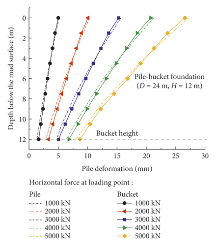
Figure 7 shows the horizontal displacement of the monopile foundation and five pile–bucket foundations below the mud surface under five loading conditions. After the monopile foundation is strengthened by attaching a bucket to form the pile–bucket foundation, the horizontal displacement decreases significantly, which indicates that the foundation stiffness increased significantly. Under horizontal loads, the depth of the rotation center of the foundation from the mud surface decreased by approximately 2.5–7.5 m.
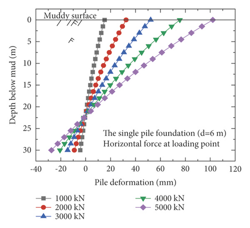
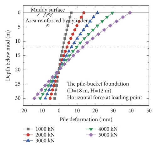
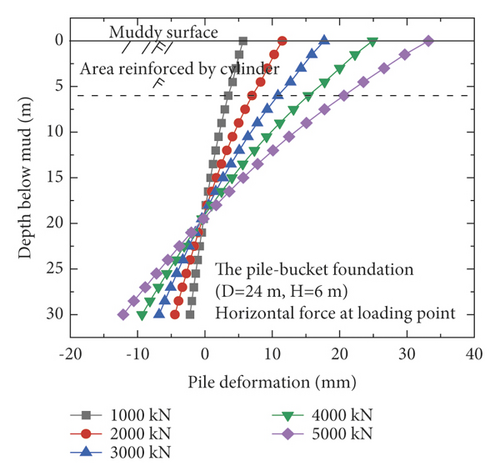
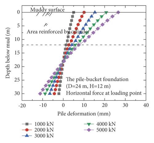
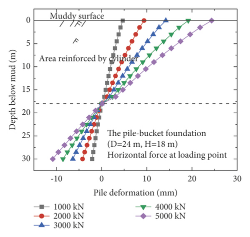
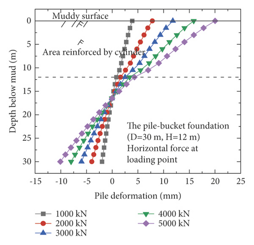
The horizontal displacement of the pile at the mud surface is adopted as a reference to intuitively compare the difference in horizontal displacements of the pile for the different foundations. The maximum horizontal displacements of the pile at the mud surface ofti different foundations are listed in Table 5.
| Model type | Displacement under different loads (m) | ||||
|---|---|---|---|---|---|
| 1,000 kN | 2,000 kN | 3,000 kN | 4,000 kN | 5,000 kN | |
| The single pile foundation (d = 6 m) | 15.22 | 32.47 | 52.19 | 75.56 | 102.01 |
| The pile-bucket foundation (D = 18 m and H = 12 m) | 6.75 | 13.76 | 21.32 | 29.64 | 39.43 |
| The pile-bucket foundation (D = 24 m and H = 6 m) | 5.67 | 11.49 | 17.71 | 24.90 | 33.19 |
| The pile-bucket foundation (D = 24 m and H = 12 m) | 4.99 | 10.07 | 15.30 | 20.77 | 26.59 |
| The pile-bucket foundation (D = 24 m and H = 18 m) | 4.67 | 9.39 | 14.21 | 19.17 | 24.35 |
| The pile-bucket foundation (D = 30 m and H = 12 m) | 3.89 | 7.81 | 11.80 | 15.86 | 20.02 |
The horizontal displacement of the pile at the mud surface increases with the load (Table 5). Moreover, the horizontal displacements of the pile–bucket foundations are significantly smaller than those of the monopile foundation. Considering the load of 3,000 kN as an example, the horizontal displacements of the pile–bucket foundations with different sizes are found to be 59–77% lower than that of the monopile foundation. It is observed that the horizontal bearing capacity of the pile–bucket foundation is significantly higher than that of the monopile foundation. After the calculation is performed, the displacement of the pile–bucket foundation decreases by 7–12% with increasing bucket diameter and by 2–5% with increasing bucket height. Thus, it can be found that the horizontal bearing capacity of the pile-bucket foundation is greater than that of the monopile foundation. Under the same horizontal load, the horizontal displacement of the pile-bucket foundation is significantly reduced compared with the monopile foundation. Changing the outer diameter of the bucket has a greater impact on the displacement of the pile body compared with changing the bucket height.
4.2. Comparison of Bending Moments
Figure 8 shows the variations in the bending moment for the pile, bucket, and the pile–bucket combined in the reinforcement section of model 3 (D = 24 m and H = 12 m) under five different loading conditions. A comparison of the three figures shows that the pile exhibits a higher bending moment than the bucket and provides most of the sufficient anti-overturning moment for the pile–bucket foundation under horizontal loads.
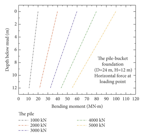
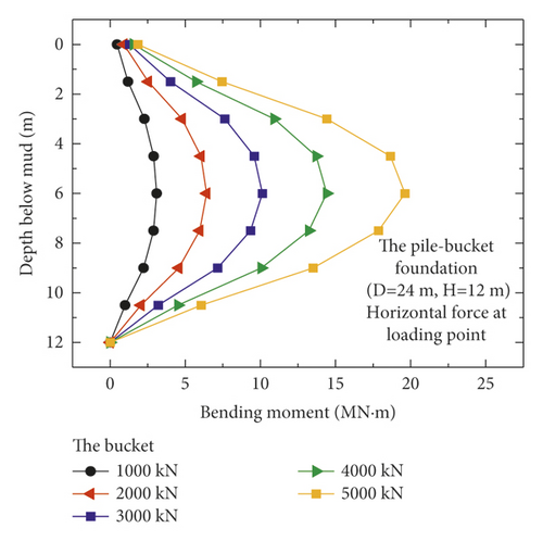
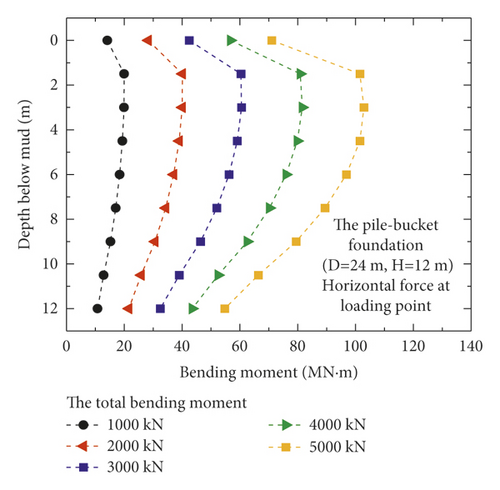
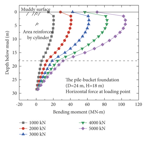
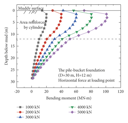
Figure 9 shows the bending moments of the monopile foundation and five pile–bucket foundations under five different loading conditions. The maximum bending moments of the pile–bucket foundations with different bucket sizes do not vary significantly. However, after the monopile foundation is strengthened by using the bucket to form the pile–bucket foundation, the bending moment decreases to a certain extent, and the position of the maximum bending moment moves upward.
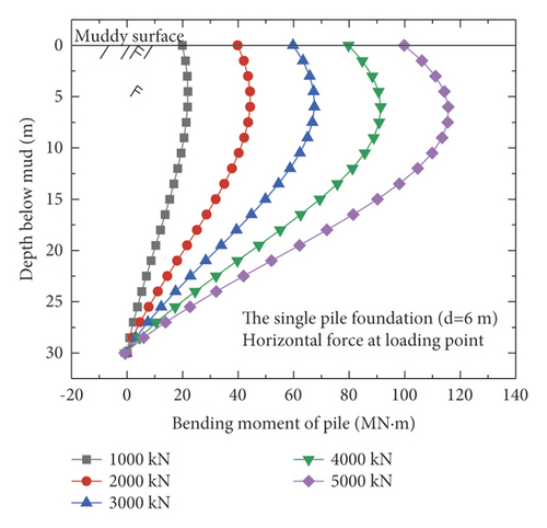
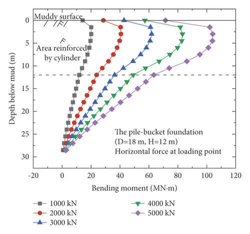
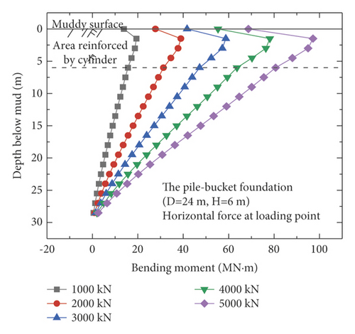
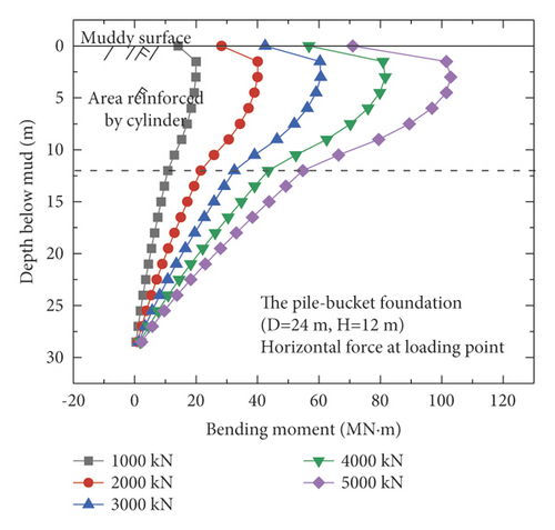
4.3. Comparison of Soil Reaction Forces
The reaction forces of the soil acting on the pile and bucket in the reinforcement section of model 3 (D = 24 m, H = 12 m) were extracted (Figure 10) to evaluate the contribution of the pile and bucket, respectively, toward the horizontal bearing capacity. Under the five different loading conditions, the bucket carries more than 90% of the soil reaction force in the reinforcement section for each case (Figure 10). In other words, the bucket is the primary load-bearing component of the pile–bucket foundation under horizontal loads.
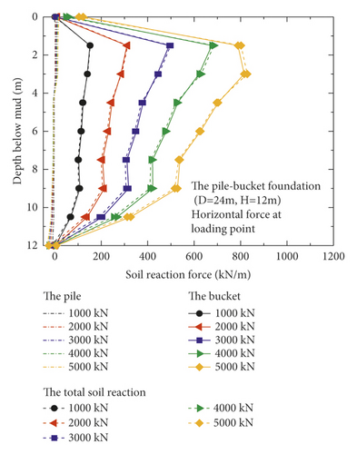
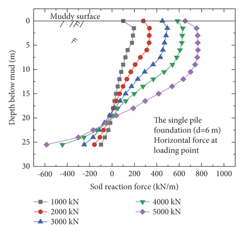
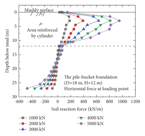
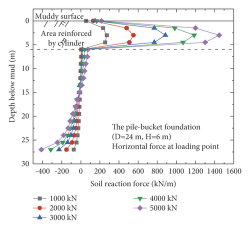
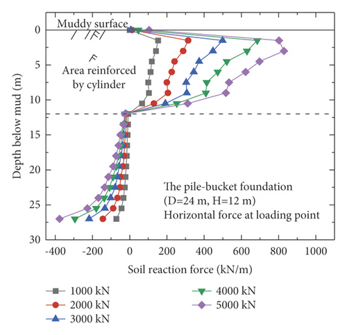
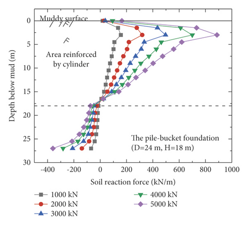
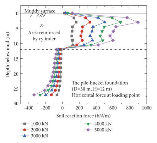
Figure 11 shows the distribution of the soil reaction force over the monopile foundation and the five pile–bucket foundations under different loading conditions. The soil reaction force is somewhat uniformly distributed around the monopile foundation, but it is mainly provided by the soil around the pile within twice the depth of the pile diameter. However, the pile–bucket foundation exhibits a reaction force different from that of the monopile foundation. Under similar loading conditions, the section reinforced with the bucket resisted a significant amount of the soil reaction force, and the remaining section of the reinforcement bears the lower soil reaction forces. In addition, it can be seen from Figure 11 that the turning point depth of soil reaction of the pile-bucket foundation is approximately the same as the height of the bucket.
4.4. Comparison of p–y Curves
Currently, the p–y curve method is recognized as the most effective analysis method for determining the horizontal nonlinear deformation of pile foundations and is widely used in conventional analyses of the horizontal deformation of pile foundations. The p–y curve method is adopted by the American Petroleum Institute (API) (2010). However, the p–y curve provided in the API code is typically suitable for pile foundations with diameters less than 1.5 m and unsuitable for large-diameter monopiles [19, 20]. In this section, the differences in the p–y curves for the monopile and pile–bucket foundations at different depths are presented. Figure 12 depicts the p–y curves of the monopile foundation and five pile–bucket foundations at different depths. It can be seen that within the depth range of the bucket (2d), the p–y curve of the monopile foundation is compared with those for the pile-bucket foundation.
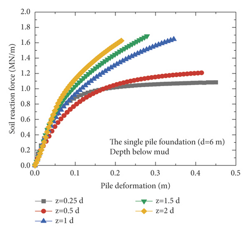
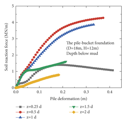
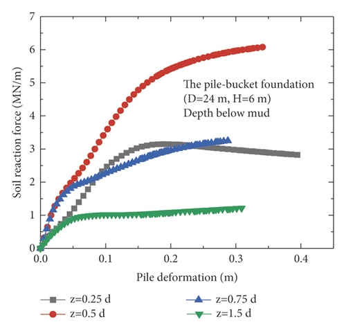
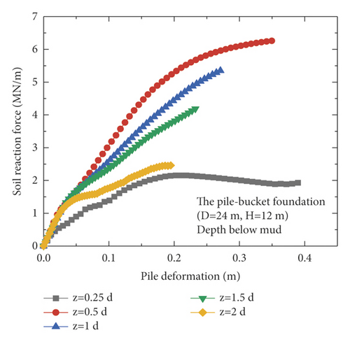
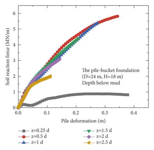
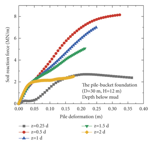
The ultimate horizontal resistance of the shallow soil around the monopile foundation continuously increased with depth, and the increase rate exhibits an initial increase followed by a decrease (Figure 12(a)). However, the p–y curves of the pile–bucket foundations are different from that of the monopile foundation. For the soil layer closer to the mud surface, the horizontal ultimate soil reaction of the pile-bucket foundation shows a trend of first increasing and then decreasing. While for the soil layer far away from the mud surface, the pile-bucket foundation shows the same variation law as the monopile foundation (Figure 12(b)–12(f)).
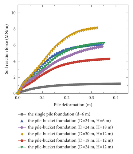
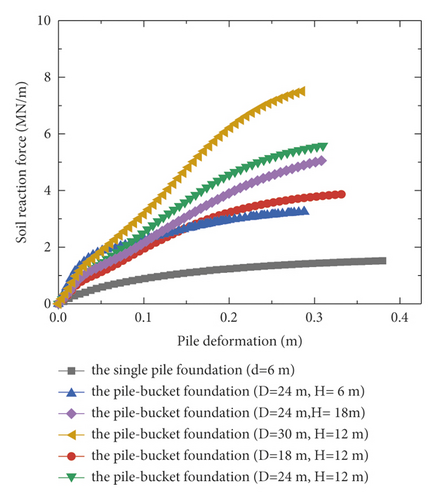
The p–y curves at depths of 0.5d (3 m) and 0.75d (4.5 m) are used as examples of plotting the p–y curves of the foundations (Figure 13) to analyze the difference between the p–y curves of the monopile foundation and pile–bucket foundations with different bucket sizes. Furthermore, the horizontal ultimate soil reactions of the pile–bucket foundation with different bucket sizes are compared with those of the monopile foundation in Table 6 depths of 0.5d (3 m) and 0.75d (4.5 m) Table 7.
| Model type | Ultimate soil reaction force | Improvement |
|---|---|---|
| Pult/MN (m) | (%) | |
| The single pile foundation (d = 6 m) | 1.52 | — |
| The pile-bucket foundation (D = 18 m and H = 12 m) | 3.86 | 153.95 |
| The pile-bucket foundation (D = 24 m and H = 6 m) | 3.25 | 113.82 |
| The pile-bucket foundation (D = 24 m and H = 12 m) | 5.58 | 267.11 |
| The pile-bucket foundation (D = 24 m and H = 18 m) | 5.05 | 232.24 |
| The pile-bucket foundation (D = 30 m and H = 12 m) | 7.51 | 394.08 |
| Model type | Ultimate soil reaction force | Improvement |
|---|---|---|
| Pult/MN (m) | (%) | |
| The single pile foundation (d = 6 m) | 1.20 | — |
| The pile-bucket foundation (D = 18 m and H = 12 m) | 4.27 | 255.83 |
| The pile-bucket foundation (D = 24 m and H = 6 m) | 6.07 | 405.83 |
| The pile-bucket foundation (D = 24 m and H = 12 m) | 6.26 | 421.67 |
| The pile-bucket foundation (D = 24 m and H = 18 m) | 5.81 | 384.17 |
| The pile-bucket foundation (D = 30 m and H = 12 m) | 8.14 | 578.33 |
It is found that at the same depth of shallow soil, the maximum horizontal ultimate resistance of the soil increases by up to 7 times after the monopile foundation is strengthened using the bucket (Figure 13, Tables 6 and 7). In addition, an increase in the reinforcement height of the bucket had a limited effect on the ultimate horizontal resistance of the pile–bucket foundation at a certain depth. For pile–bucket foundations with the same bucket diameter, the ultimate horizontal resistance of the soil initially increases and subsequently decreases with increasing bucket height. At a certain bucket height, the ultimate horizontal resistance of the pile–bucket foundation increases with the bucket diameter. The variation in the bucket diameter has a more significant influence on the ultimate horizontal resistance of the soil than that in the bucket height.
5. Determination of Fundamental Frequency Using the FEM-Analysis Combined Method
In addition to the horizontal bearing capacity, the natural frequency of a structure is also a critical parameter. A new method of solving the fundamental frequency problem of structures, known as the FEM–analysis combined method, was applied, and the accuracy of this method was verified. The differences in the fundamental frequencies of the monopile and pile–bucket foundations were analyzed. The following observations were noted.
5.1. Application and Verification of FEM-Analysis Combined Method
The FEM-analysis combined method involves the application of the FEM for modeling the substructure (to determine the foundation stiffness), and subsequently, the FEM is combined with detailed parameters of the upper structure using the analytical method (to solve the first-order natural frequency of the structure).
The analytical method is based on the process reported by Bhattacharya et al. [12], Bhattacharya et al. [13], and Adhikari et al. [14], where the foundation was divided into two springs with lateral stiffness and rotational stiffness. The monopile foundation was established by referring to the foundation parameters of the North Hoyle wind farm in the UK [21]. The height of the upper tower is 70 m, and the diameter of the tower is converted according to the average bending rigidity of the tower, which is 2.45 m. The rotor and blade systems are idealized as a mass block with a top mass of 100,000 kg. The diameter, length, and wall thickness of the pile are 4 m, 33 m, and 50 mm, respectively. The North Hoyle wind farm is mainly composed of clay and sand layers, and the average shear modulus of the foundation soil is 230 MPa. The modeling process is consistent with that described in Section 3. After the finite element model was developed, horizontal forces and bending moments were applied to the top of the pile. The simplified stiffness parameters of the foundation were obtained from the initial tangent slope of the load-displacement curve and the moment-rotation curve of the elastic stage. Thereafter, by combining the foundation stiffness parameters and the upper structure parameters, first-order natural frequencies were determined using the analytical method.
The results obtained using the FEM-analysis combined method were then compared with three sets of values to verify the feasibility of the FEM-analysis combined method. These values were the measured values, analytical values obtained after simplifying the foundation stiffness, and predicted values obtained using the FEM. For the analytical values obtained after simplifying the foundation stiffness, the simplified method provided in Eurocode 8 (2001) was adopted. The predicted value obtained using the FEM was calculated using the Block Lanczos method [22] after the entire model of the structure was established.
The first-order natural frequencies obtained using the three methods, the measured values, and the numerical deviations are listed in Table 8. It is found that the values of the first-order natural frequency of the monopile foundation, computed using the FEM-analysis combined method, are similar to the measured values. Compared to the other two methods, the errors between the FEM-analysis combined method and the measured method are within 5%, which indicated that the FEM-analysis combined method can be used to accurately predict the first-order natural frequency of the structure, which minimum resonance.
| The measured value | The predicted value by the FEM-analysis combined method | The predicted value by the finite element method | The analytical value after simplifying foundation stiffness | |
|---|---|---|---|---|
| The first-order natural frequency (Hz) | 0.369 | 0.359 | 0.328 | 0.342 |
| The numerical deviation (%) | — | 2.7 | 11.1 | 7.3 |
5.2. Comparison of Fundamental Frequency between Monopile and Pile-Bucket Foundations
Based on the foundation parameters of the North Hoyle wind farm [21], finite element models of monopile foundations with three different pile diameters and pile-bucket foundations with five different bucket sizes were developed to obtain the foundation stiffness. The calculated foundation stiffness of each model was dimensionless, and the results are presented in Table 9.
| Type of foundation | Number | kl N (mm) | kr MN·(m/rad) | ηl = klL3/EI | ηr = krL/EI |
|---|---|---|---|---|---|
| The single pile foundation (d = 4 m) | 1 | 38,464 | 9,257 | 99.1966 | 4.8721 |
| The single pile foundation (d = 5 m) | 2 | 53,936 | 16,064 | 139.0981 | 8.4547 |
| The single pile foundation (d = 6 m) | 3 | 67,955 | 24,244 | 175.2524 | 12.7600 |
| The pile-bucket foundation (D = 16 m and H = 4 m) | 4 | 52,527 | 10,593 | 135.4644 | 5.5753 |
| The pile-bucket foundation (D = 16 m and H = 8 m) | 5 | 53,888 | 10,731 | 138.9743 | 5.6479 |
| The pile-bucket foundation (D = 16 m and H = 12 m) | 6 | 54,265 | 10,768 | 139.9466 | 5.6674 |
| The pile-bucket foundation (D = 20 m and H = 8 m) | 7 | 55,048 | 10,786 | 141.9659 | 5.6768 |
| The pile-bucket foundation (D = 12 m and H = 8 m) | 8 | 52,069 | 10,640 | 134.2832 | 5.6000 |
Among the abovementioned models, model Nos. 1, 2, and 3 denote monopile foundations with diameters of 4, 5, and 6 m, respectively. The monopile foundation with a pile diameter of 4 m is consistent with the monopile foundation parameters of the North Hoyle wind farm. Model Nos. 4–8 are comparison models of the pile-bucket foundation with a pile diameter of 4 m. In model Nos. 4–6, bucket height is selected as a variable, whereas in model Nos. 5, 7, and 8, bucket diameter is chosen as a variable.
After the dimensionless foundation stiffness parameters were obtained, the first-order natural frequency of the structure was determined using the analytical method described by Bhattacharya et al. [12], Bhattacharya et al. [13], and Adhikari et al. [14]. The solution results are presented in Table 10.
| Type of foundation | The monopile foundation, d = 4 m | The monopile foundation, d = 5 m | The monopile foundation, d = 6 m |
|---|---|---|---|
| The predicted value by the FEM-analysis combined method (Hz) | 0.359 | 0.394 | 0.415 |
Table 10 shows the first-order natural frequencies of the three types of monopile foundation structures with different pile diameters, which were obtained using the FEM-analysis combined method. Variations in pile diameter influence the fundamental frequency. The calculated natural frequency increases by approximately 5.3–9.7% for an increase of 1 m in the pile diameter. Additionally, in Table 11, the rate of increase in the fundamental frequency decreases with increasing pile diameter.
| Type of foundation | The monopile foundation, d = 4 m | The pile-bucket foundation, D = 16 m and H = 4 m | The pile-bucket foundation, D = 16 m and H = 8 m | The pile-bucket foundation, D = 16 m and H = 12 m | The pile-bucket foundation, D = 20 m and H = 8 m | The pile-bucket foundation, D = 12 m and H = 8 m |
|---|---|---|---|---|---|---|
| The predicted value by the FEM-analysis combined method (Hz) | 0.359 | 0.368 | 0.369 | 0.369 | 0.370 | 0.368 |
The fundamental frequency values for different foundations, determined using the FEM-analysis combined method, are listed in Table 11. Among the foundations, the monopile foundation of 4 m is used as the reinforced foundation. Through calculations, the first-order natural frequencies of the pile-bucket foundation are found to be 2.5–3% higher than those of the monopile foundation. In other words, the natural frequency increases significantly after the monopile foundation is strengthened using a bucket to form the pile-bucket foundation. Overall, the differences in fundamental frequencies of the pile-bucket foundations with different bucket sizes are minimal. Therefore, the effects of bucket height and bucket diameter on natural frequency are deemed insignificant.
6. Conclusion
- (1)
Compared to the monopile foundation, the pile-bucket foundation is more effective in improving the foundation stiffness, natural frequency, and load-bearing capacity of offshore wind turbines. The pile resists more bending moments than the bucket in the reinforced section of the pile-bucket foundation. The main bearing component of the pile-bucket foundation under horizontal loads is the bucket, which bears more than 90% of the soil reaction force in the reinforced section.
- (2)
At the same depth of shallow soil, the maximum horizontal ultimate resistance of the soil increases by up to 7 times after the monopile foundation is strengthened using a bucket. Variations in bucket diameter have a more significant impact on the improvement of the ultimate horizontal resistance of the soil than those in bucket height.
- (3)
The deviation between the results of the FEM-analysis combined method and the measured values is within 5%. Thus, the FEM-analysis combined method can be used to predict the first-order natural frequencies of structures precisely and rapidly in order to minimize resonance. Increasing the pile diameter increases the fundamental frequency of the structure. The natural frequency increases significantly after the monopile foundation is strengthened using a bucket to construct the pile-bucket foundation. Compared with the monopile foundation, the pile-bucket foundation can increase the natural frequency, which can be considered a possible reinforcement measure for the wind turbine foundation constructed in soft soils.
Conflicts of Interest
The authors declare that they have no conflicts of interest.
Acknowledgments
The authors gratefully acknowledge the financial support provided by National Natural Science Foundation of China (51909249).
Open Research
Data Availability
No data were used to support this study.


