Experimental and Numerical Investigation of Seismic Performance of UHPC Thin-Walled Short Piers
Abstract
Rigid frame bridges with different heights of adjacent piers are inclined to crack the main girder at the pier-beam connection. This cracking occurs due to a significant difference in thrust stiffness between tall and short piers. This problem can be resolved by applying ultra-high performance concrete (UHPC) materials. Thus, in the present paper, the seismic performance and failure behavior of UHPC thin-walled short piers were tested under low-frequency cyclic loads. Based on previous studies, the test was conducted using a proposed experimental model, where the effects of longitudinal reinforcement ratio, stirrup reinforcement ratio, and axial load ratio were considered. The failure mode, ultimate bearing capacity, stiffness, displacement ductility factor, and other performance parameters were analyzed. It was found that the specimens present the bending-shear failure mode. Also, the load-bearing capacity of the UHPC thin-walled piers was significantly improved by increasing the longitudinal ratio of the thin-walled short piers, while the contribution of the stirrup ratio was limited. In addition, compared with traditional short piers, the ductility of UHPC thin-walled short piers increased by 53.36%, and the thrust stiffness decreased by 23.73%, indicating that UHPC thin-walled short piers have more efficient seismic performance than RC short piers. Note that, in the present paper, UHPC thin-walled short piers’ internal behavior was also analyzed by establishing a finite element model. The analysis proves that the numerical results are consistent with the experimental data, which is promising to better understand the failure behavior.
1. Introduction
Continuous rigid frame bridges that are widely used along with high-grade road construction have outstanding features for bridge engineering, including higher structural integrity, more ability to leapfrog, less pollution, and mature construction technology [1]. Since rigid frame bridge piers are the main load-bearing and lateral-force members, these piers’ ductility design and seismic performance are key issues in the seismic study of bridges [2]. In curved rigid frame bridges and those having an irregular column-stiffness distribution, short piers affected by concrete shrinkage and creep, temperature, and earthquakes are prone to some problems. These problems that include inconsistent deformation of pier beams and cracks in the consolidation of pier beams are caused by significant differences between mechanical properties of tall and short piers. Therefore, under the premise of meeting the bearing capacity requirements of short piers, how to reduce short piers’ thrust stiffness and improve their ductility and other seismic performance have become challenging.
Since Larrard et al. [3] proposed the concept of ultra-high performance concrete (UHPC) in 1994, UHPC has rapidly become a research hotspot in the field of civil engineering in recent years due to its excellent mechanical properties and durability [4]. Recently, the fast development of UHPC is promising to resolve the aforementioned issues. Note that many experimental and theoretical studies were conducted on the UHPC’s mechanical properties, including tensile and compression performance, durability, flexural performance, and shear resistance. For example, to determine the basic mechanical behaviors of UHPC, compressive strength, three-point bending strength, briquette tensile, and split tensile tests were carried out on cylinders and cubes. Some studies have shown that the UHPC’s compressive strength is three to four times that of ordinary concrete, and the elasticity modulus is about twice that of ordinary concrete [5]. As another example, heat-treatment and Brazilian splitting tests were conducted to evaluate the UHPC’s durability, which is significantly different from standard mortar (M1) and conventional concrete. These tests showed that the gas permeability of ultra-high performance reinforced concrete remains almost unchanged, implying good durability [6]. Moreover, Shao et al. [7] reported that the UHPC’s bending toughness is reliable, and, under bending and tensile deformations, its strength is still around 1.17–2.43 times the initial crack strength. In addition, Tong [8] showed that UHPC presents extraordinary mechanical properties, including greater compressive and tensile strengths, excellent toughness, and energy dissipation capacity.
UHPC increases the components’ density and activity so that the material’s compressive strength is 3-4 times that of ordinary concrete. Also, the pores and microcracks inside the material are greatly reduced so that the dimensions of components and the number of steel bars can be effectively reduced. In addition, compared with ordinary concrete under the same bearing capacity, the axial load ratio of UHPC decreases, so that the ductility and energy consumption are improved [9]. Steel fiber added to UHPC significantly improves UHPC’s bending toughness and energy consumption performance [10]. In the present study, based on the aforementioned material and structure factors, a UHPC thin-walled pier structure is proposed. This proposed structure aims to reduce the thrust rigidity of short piers in ramp rigid frame bridges and rigid frame bridges with irregular stiffness distribution. In addition, this structure aims to improve the seismic resistance of short piers. The reduction in the cross-sectional sizes decreases the cost of UHPC thin-walled piers. Also, the excellent durability makes the UHPC piers’ lifetime cost the same as traditional thin-walled reinforced concrete piers.
Deng et al. [11] explored the seismic performance of UHPC components of reactive powder concrete short columns. For this purpose, they analyzed several UHPC’s short piers under low cyclic loading. Xu et al. [12] investigated the seismic behaviors of UHPC columns. They also studied the failure mode, hysteresis curve, envelope hoop, strength and stiffness, ductility, and the energy dissipation of UHPC columns under low cyclic loading. It is worth mentioning that other quasi-static studies were also carried out by many researchers, exemplified by Hao et al. [13] and Ju et al. [14]. The above studies indicate that the seismic performance of the UHPC piers can meet seismic requirements in China.
Many studies on the seismic performance of UHPC piers have been reported in the literature. Milad et al. [15] and Zhang et al. [16], considering concrete strength grade and eccentric compression, conducted several experiments in which the strength, ductility, and failure mechanism of UHPC columns under pure axial loads were studied. Also, Yang et al. [17] and Zhao et al. [18] proposed UHPC precast bridge piers structures and compared them with overall piers. Fan et al. [19], using the falling dart test, examined the impact performances of UHPC columns. The results showed that when the UHPC material is added to lateral-force and load-bearing components, either prefabricated or integral cast-in-place, they have excellent pressure-bearing performance and impact resistance.
Chung et al. [20] found that the inclusion of steel fibers with a volume fraction of 0.75% or more effectively restrained spalling and crushing of the slender UHPC columns. Ye et al. [21] studied the seismic failure mode and dynamic response characteristics of a UHPC rectangular hollow bridge pier and eight finite element analysis models were examined on a shaking table test. The results showed that the overall seismic performance of UHPC hollow piers is excellent. To evaluate the UHPC piers’ seismic performance, Hu et al. [22] conducted quasi-static tests on four UHPC piers under reversed cyclic lateral loading. Therefore, UHPC has been widely used in pressure-bearing structures. However, the previous studies have mainly focused on evaluating UHPC segment prefabricated piers’ seismic performance and on numerical simulation of UHPC hollow piers and UHPC columns. Thus, there is a lack of relevant studies on the seismic performance of UHPC thin-walled piers. There are few reference materials for applying UHPC materials on short piers of continuous rigid frame bridges. At present, UHPC is applied to a small number of arch bridges. The UHPC thin-walled short pier proposed in this paper is a solution to the problem of low piers with high thrust stiffness and easy to withstand earthquakes. For the new structure with the problem of failure, there are few studies on the seismic performance of this new structure. So far, no other engineering examples of using UHPC in continuous rigid frame bridge piers with short piers have been found. Therefore, it is of great scientific significance to conduct in-depth and systematic research on this new type of bridge pier form, which also has good practical significance for the application and promotion of UHPC thin-walled short piers in the future and for guiding similar engineering practices.
In the present study, under low-frequency cyclic loading, quasi-static tests were performed on six specimens of UHPC thin-walled piers. The failure mode, load-displacement curve, ductility, and energy dissipation capacity of the specimens were analyzed. Also, the fine finite element model of UHPC thin-walled short piers was established. The combination of numerical analysis results and experimental data is helpful to better understand the seismic performance of the structure, and suggestions for the design of this pier were put forward.
2. Test Setup and Specimen Properties
In this section, the sample materials, the mechanical properties of the material and test loading scheme used in this study were explained in detail. Note that these tests were designed to examine the mechanical properties of test materials under low-cyclic repeated loading and verify their bearing capacity.
2.1. Model Design
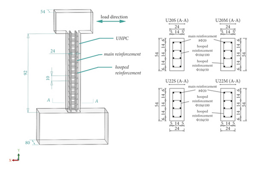
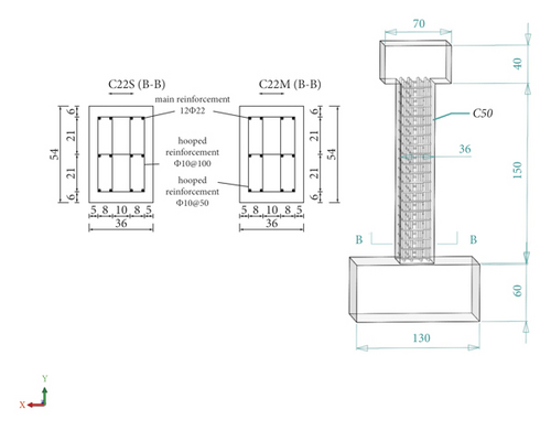
In the present study, six thin-walled short piers, including four UHPC piers and two reinforced concrete (RC) piers, were designed and produced using common thin-walled short piers used in the prototyped urban viaducts, and following the local and global design specification. The pier’s internal structure design is shown in Figure 1. The UHPC pier dimensions were 240 × 540 × 920 mm, and the RC pier dimensions were 360 × 540 × 1500 mm. The column footing size was 1300 × 800 × 600 mm, and the size of the beam on column’s top was 700 × 540 × 400 mm. Note that the specimen test parameters, including the axial pressure ratio, concrete specification, longitudinal rebar’s diameter, and stirrup ratio, are presented in Table 1.
| Group | Concrete | Ring rebar, Ф (mm) | Axial pressure ratio | Longitudinal rebar, Ф (mm) | Stirrup ratio (%) |
|---|---|---|---|---|---|
| U20S | UHPC | 10 | 0.1 (Figure 1) | 20 | 4.79 |
| U20 M | UHPC | 10 | 0.1 | 20 | 5.50 |
| U22S | UHPC | 10 | 0.1 | 22 | 4.79 |
| U22 M | UHPC | 10 | 0.15 | 22 | 5.50 |
| C22S | C50 | 10 | 0.15 | 22 | 4.79 |
| C22 M | C50 | 10 | 0.15 | 22 | 5.50 |
2.2. Mechanical Properties
In this paper, the material properties of concrete and steel were tested to obtain the mechanical properties of materials. In the UHPC pier, the 42.5 MPa ordinary Portland cement was used. Also, the steel fiber was round and straight. The length of steel fiber was 8 mm, and the diameter was 0.12 mm. Chen et al. [23] showed that the splitting tensile strength of UHPC is the best when the volume content of steel fiber is 1.0–2.5%. Therefore, the volume content of steel fiber used in this study was 1.5%. After pouring, the steel fiber was maintained by steam for 48 h. Note that, in the RC pier, the C50 commercial concrete was used and it was completed by one-time pouring. After two days, the formwork was removed, and after seven days of sprinkler maintenance, it was naturally maintained for 28 days. According to the standard of an ordinary concrete mechanical performance test method, for compressive strength tests, each test pier specimen was made of 100 × 100 × 100 mm standard concrete cube test blocks. For elastic modulus tests, each test pier specimen was made of 100 × 100 × 300 mm prism test blocks and for flexural strength tests, the specimen was made of 100 × 100 × 400 mm prism test blocks. The test block and the test pier were maintained under the same conditions, and the concrete mechanical performance test was conducted before loading the test pier. Note that the mechanical properties of concrete were tested according to the standard test procedure. The results are shown in Table 2. Also, Table 3 presents the tensile test results of steel sheets from the same batch of steel as the rebars.
| Specification | Compressive strength, (MPa) | Rupture strength, (MPa) | Modulus of elasticity, (GPa) |
|---|---|---|---|
| UHPC | 120.8 | 28.1 | 43.7 |
| C50 | 58.1 | 6.5 | 35.5 |
| Diameter, Ф (mm) | Yield strength, fy (MPa) | Ultimate strength, fu (MPa) | Yield strain, εy |
|---|---|---|---|
| 10 | 235.6 | 448.5 | 0.0021 |
| 20 | 370.5 | 661.6 | 0.0022 |
| 22 | 390.2 | 668.5 | 0.0022 |
2.3. Loading Facility
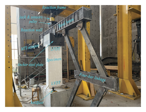
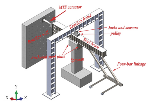
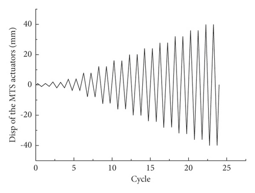
Note that a similar test setup was used for all specimens. A steel beam structure loading device was specifically designed for thin-walled short piers’ characteristics, which was placed on the top of the specimens, and it was connected to the specimen through the anchor plate at the bottom of the steel beam. The steel beam consisted of a reaction beam, a vertical Jack, and a pulley trolley. The vertical Jack provided the vertical load, and the electro-hydraulic servo system provided the horizontal load. Also, the size and direction of the axial pressure ratio were kept constant during the test. Before the test, the electronic displacement meter was installed at the top of the test pier to test the horizontal displacement of the pier. The stress and strain of concrete were tested by setting measuring points 100 mm from the bottom of the pier and reinforcing the pier and beam. In addition, paint latex on the surface of the test pier was used to observe the crack development and failure process of the pier. The loading device is shown in Figure 2, and the loading protocols are shown in Figure 3.
2.4. Measurement Plan
Following the American Concrete Association’s guideline for reinforced concrete testing ACI 374 [24], the displacement-controlled variable amplitude loading method was adopted in the quasi-static tests. Each level was cycled twice, and the load was held for five minutes. Note that the test pier was assumed to be damaged when either the loading capacity of the test pier dropped to 85% of the peak load of the test pier, or the specimen was severely damaged.
3. Phenomenon and Modalities
During the test, the damage process, load-bearing capacity, and failure modes were tracked and recorded. The failure of all specimens included three stages, namely, elastic stage, elastic-plastic stage, and plastic failure stage. With the increase of load, the failure mode of the specimen was more obvious, and it was easier to track and record the cracks. Note that the failure modes of the UHPC thin-walled pier and the RC pier were similar and mainly showed the “bending-shear failure mode”.
3.1. UHPC Specimen Failure Phenomenon
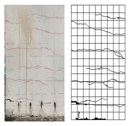
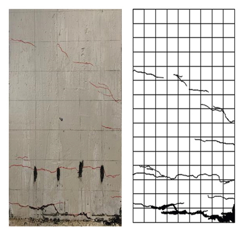
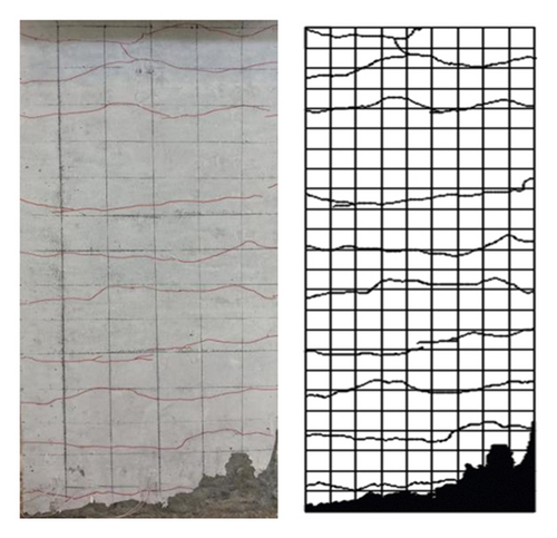
The failure process and modes of all UHPC model tests were essentially identical. Thus, the U22S pier model test was chosen as a representative and was presented in this section. In the U22S pier model test, when the horizontal load on the pier’s top reached 142 kN, a 14 cm long transverse crack appeared on the top of the pier’s north facade. When the load reached 164 kN, multiple transverse cracks appeared on the pier’s north facade, and the highest transverse crack was 68 cm from the pier’s bottom, accompanied by a small amount of main reinforcement yielding. Finally, when the load reached 196 kN, the horizontal cracks on the north and south facades penetrated, and the concrete at the pier’s edge was peeled off. Also, the cracks no longer developed, and seven horizontal cracks occurred on the pier. The crack and failure modes are shown in Figure 4.
3.2. RC Specimen Failure Phenomenon
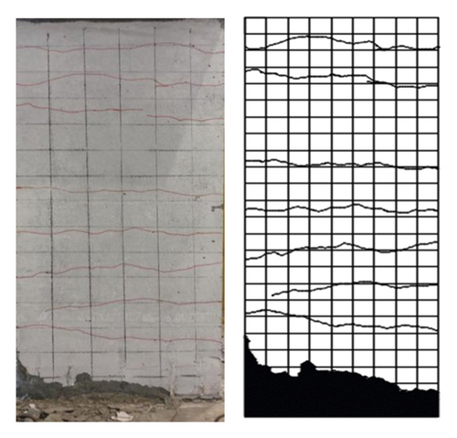
In the RC pier test, when the load on the pier’s top was 70.26 kN, two transverse cracks occurred on the front and back sides of the bottom of the C22S pier, and the heights from the bottom of the pier were 10 and 15 cm, respectively. In addition, two transverse cracks occurred on the pier’s top. When the load on the pier’s top reached 119.04 kN, eight longitudinal horizontal cracks occurred on the north elevation of the pier’s bottom. The highest crack was at 60 cm from the pier’s bottom. Also, 10 longitudinal horizontal cracks occurred on the south elevation, and the concrete on the front and rear sides of the pier’s bottom was peeled off. In the subsequent loading, the transverse cracks’ widths gradually increased, but no new cracks appeared. The final failure modes are shown in Figure 4.
4. Experimental Results
4.1. Hysteresis Curves
As indicated by Yao [25], the hysteresis curve can comprehensively reflect the structure’s mechanical characteristics, such as deformation performance, energy dissipation performance, and seismic performance. The force-column top displacement hysteresis curves of the specimens are shown in Figure 5.
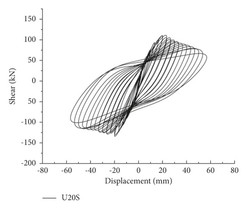
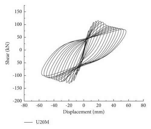
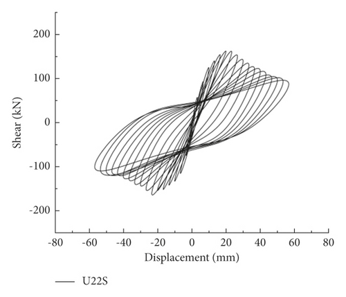
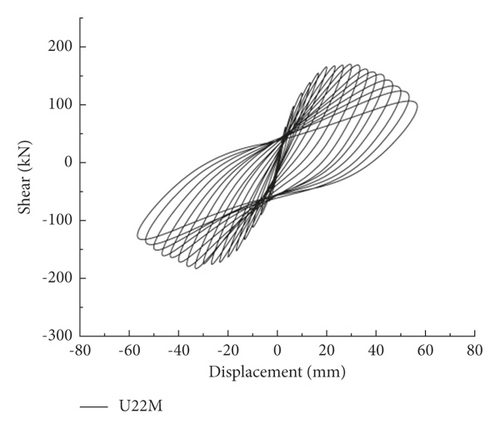
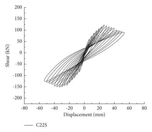
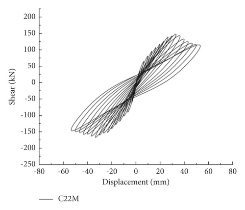
In the hysteresis curve of the UHPC pier, the difference between the hysteresis curves of U20S and U20M was not obvious, while the peak load of the U22S hysteresis curve obviously increased. However, the load of U22S decreased more obviously after the load reached the peak, indicating that the axial load ratio is improved. The increase in the reinforcement ratio of the main reinforcement can increase the thrust resistance and reduce the ductility.
Note that the hysteresis curve characteristics of RC piers were similar to UHPC piers. However, since UHPC improves the fineness and activity of the components, the pores and microcracks inside the material are reduced. Thus, the hysteresis curve of UHPC piers is fuller than that of RC piers.
4.2. Skeleton Curves and Energy Dissipation
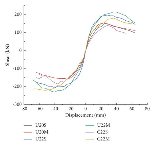
The envelope connected by the peak point, i.e., unloading vertex, of each level of cyclic loading in the hysteresis curve of the test piers was taken as the skeleton curve. The skeleton curves of each specimen are shown in Figure 6.
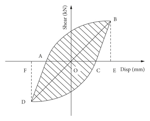
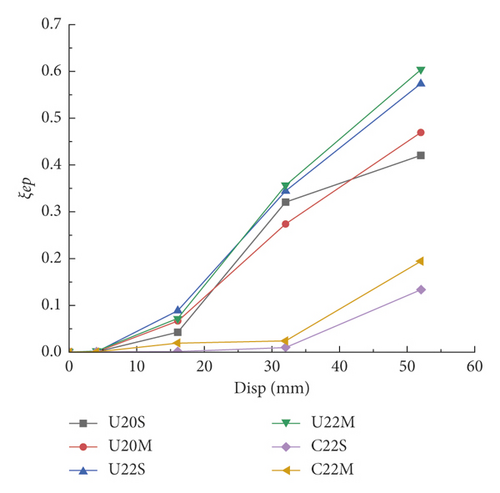
As shown in Figure 7, S(ABC + ADC) term is the energy consumed by a single hysteresis loop, and S(OBE + ODF) term is the corresponding triangular energy in a single hysteresis loop. Figure 8 shows that after reaching the peak load, the equivalent viscosity coefficients of UHPC piers were all higher than those of RC piers and were greater than 0.4, indicating that the energy dissipation capacity of UHPC piers is more effective than that of RC piers. Also, the viscous damping coefficient of the UHPC pier was higher so that the brittle compression and bending failure were avoided. Compared with U20S, the equivalent viscous damping coefficient of U22S increased by 23.7%, implying that the energy consumption capacity of the components increases with the increasing main reinforcement ratio.
4.3. Ductility and Carrying Capacity
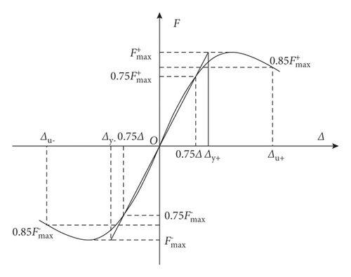
The results of displacement ductility and load of this test are shown in Table 4, in which Fy and Δy are yield load and yield displacement, respectively. In addition, Fp and Δu are the ultimate load and ultimate displacement, respectively. From Table 4, it can be seen that the UHPC piers’ displacement ductility was greater than three, indicating excellent ductility. Compared with RC piers, the maximum displacement ductility coefficient is increased by 53.36%. The ultimate load, stiffness, and ductility of U20S and U20 M were the same, implying that the increase in the stirrup ratio has little effect on the seismic performance of UHPC thin-walled short piers. U22S had 10.9% more stiffness and 5.23% less ductility than U20S.
| Specimen | Direction | Fy (kN) | Δy (mm) | Fp (kN) | Δu (mm) | Stiffness | Ductility |
|---|---|---|---|---|---|---|---|
| U20S | + | 119.03 | 17.09 | 136.21 | 42.72 | 1.82 | 3.42 |
| − | 121.79 | 18.20 | 159.43 | 43.47 | |||
| U20 M | + | 125.26 | 15.25 | 139.34 | 41.16 | 1.86 | 3.44 |
| − | 130.15 | 15.76 | 157.69 | 56.25 | |||
| U22S | + | 142.37 | 12.48 | 163.84 | 41.03 | 2.02 | 3.25 |
| − | 150.89 | 13.67 | 199.47 | 43.28 | |||
| U22 M | + | 174.38 | 17.83 | 213.60 | 46.20 | 2.12 | 3.17 |
| − | 183.12 | 20.08 | 221.53 | 48.85 | |||
| C22S | + | 125.19 | 22.74 | 149.55 | 36.52 | 2.36 | 2.89 |
| − | 125.44 | 23.48 | 199.48 | 38.35 | |||
| C22 M | + | 132.77 | 26.31 | 169.95 | 35.53 | 2.39 | 2.23 |
| − | 131.74 | 23.13 | 209.50 | 35.27 | |||
5. Finite Element Analysis
To further explore the seismic performance of UHPC thin-walled piers, a numerical model based on the finite element software ABAQUS was established. Thus, the effect of reinforcement ratio and axial load ratio on the test pier’s ductility and thrust bearing capacity can be further discussed.
5.1. Constitutive Relation
In the finite element model, the steel bar adopted the constitutive relationship of the ideal elastoplastic model, which is for an isotropic material. Before the steel bar yielded, it was in an elastic deforned stage, and after the steel bar yielded, the stress-strain relationship was a horizontal line. The steel bar’s elastic modulus and density were taken as 2.0 × 10⁵ MPa and 7850 kg/m3, respectively, and the Poisson’s ratio was taken as 0.3.
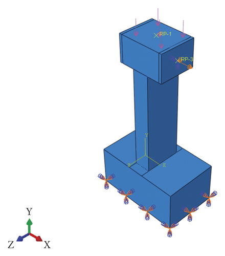
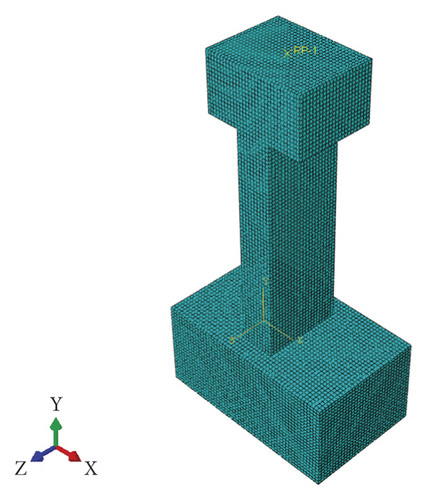
In the finite element model of the test pier, the concrete adopted eight-node reduced integral three-dimensional solid elements. Also, two-node linear three-dimensional truss elements were used for the main reinforcement and stirrup element types. In addition, a finer mesh was used for the abdomen position in the mesh division. It is worth mentioning that our previous studies have shown that the mesh size of the finite element model has a great influence on the peak strain of the model [30]. Thus, for accurate calculation, the mesh size of the finite element model is taken as 15 mm. The boundary conditions and meshing of the finite element model are shown in Figure 10.
6. Verification and Parameter Analysis
6.1. Hysteresis Performance
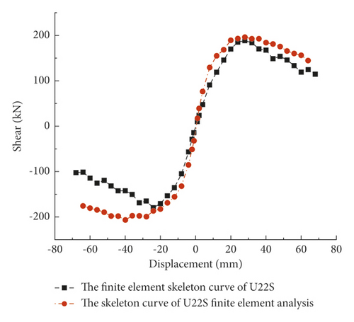
Through the above-mentioned finite element model, the pseudostatic analysis of the UHPC thin-walled short pier was carried out using the same loading method as the experiment. Taking the U22S pier as an example, the skeleton curves calculated by ABAQUS were compared with experimental results, as shown in Figure 11. It showed that when the specimen is under positive loading, cracks are generated on the tensile side of the concrete; When the specimen is under reverse loading, the closure of cracks makes the negative load’s absolute value of the skeleton curve lower than that under positive loading. It makes the positive and negative parts of the skeleton curve exhibit an asymmetric trend. Note that the finite element model does not consider the closure of cracks in the process of cyclic loading, and the degree of imbalance of the skeleton curve is small, and the decline of the skeleton curve is even less obvious. In general, the numerical results match quite well with the test curve. The above results showed that the finite element model established in the present paper is comparatively accurate.
6.2. Failure Modes
Taking the U20 M pier as an example, the calculated failure mode of the test pier under low-cycle repeated loads was compared with the experimental failure mode. Note that the numerical results are the tension and compression plastic damage cloud diagram corresponding to the peak bearing capacity, as shown in Figure 12. The Damagec refers to the plastic compressive damage of components. The Damagec stress cloud map in Abaqus can visually display the plastic damage of components during the compressive process. In the same way, the Damaget refers to the plastic tensile damage of components.
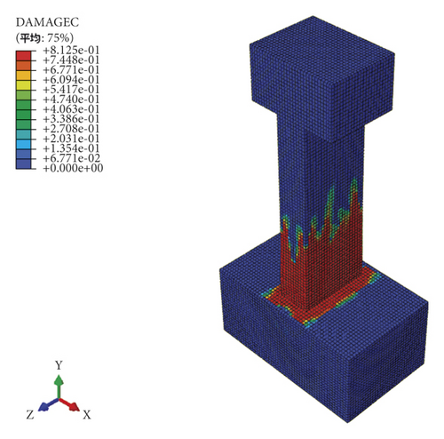
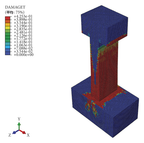
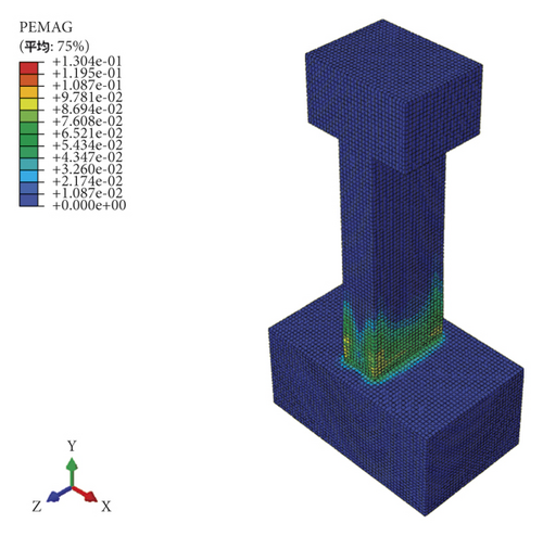
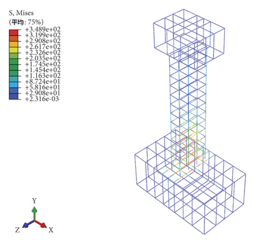
Figure 12 shows that the area with more significant plastic damage of U20 M pier was within 1/8 of the pier height from the pier base. Also, the final failure of the test pier was manifested by the critical main crack formation in the plastic-hinge region of the pier bottom. As shown in Figure 12(c), the plastic damage at the corner of the plastic hinge area of the specimen was the most serious, which is consistent with the fact that the test crack first appears at the corner. The stress nephogram of the steel bar showed that the stress concentration of the bottom steel bar is obvious and it is the first to be destroyed. It can be seen that the finite element model established in the present paper can reflect the mechanical performance and failure characteristics of the UHPC thin-walled piers under load conditions.
6.3. Parametric Analysis
Using the orthogonal test method for parameter sensitivity analysis and the above-mentioned finite element model, the effects of main reinforcement ratio, the UHPC wall thickness, and constant axial load ratio on the ductility and thrust resistance of the UHPC thin-walled short piers under low-cycle repeated loading were studied. The orthogonal test had three factors and four levels. The specific orthogonal test parameters are shown in Table 5, and the range analysis result of parameter sensitivity are shown in Table 6.
| Specimen | Longitudinal reinforcement ratio (%) | Axial pressure ratio (%) | Wall thickness (mm) | Volume matching rate (%) |
|---|---|---|---|---|
| JC-1 | 0.87 | 2 | 210 | 1.23 |
| JC-2 | 0.87 | 6 | 240 | 1.23 |
| JC-3 | 0.87 | 10 | 360 | 1.23 |
| JC-4 | 0.87 | 14 | 390 | 1.23 |
| JC-5 | 1.93 | 2 | 240 | 1.23 |
| JC-6 | 1.93 | 6 | 210 | 1.23 |
| JC-7 | 1.93 | 10 | 390 | 1.23 |
| JC-8 | 1.93 | 14 | 360 | 1.23 |
| JC-9 | 2.34 | 2 | 360 | 1.23 |
| JC-10 | 2.34 | 6 | 390 | 1.23 |
| JC-11 | 2.34 | 10 | 210 | 1.23 |
| JC-12 | 2.34 | 14 | 240 | 1.23 |
| JC-13 | 2.79 | 2 | 390 | 1.23 |
| JC-14 | 2.79 | 6 | 360 | 1.23 |
| JC-15 | 2.79 | 10 | 240 | 1.23 |
| JC-16 | 2.79 | 14 | 210 | 1.23 |
- Note: Volume matching rate (%) refers to the ratio of the stirrup volume to the corresponding concrete volume.
| Longitudinal reinforcement ratio (%) | Axial pressure ratio (%) | Wall thickness (mm) | |
|---|---|---|---|
| Stiffness | 0.552 | 1.229 | 0.622 |
| Ductility | 0.389 | 0.596 | 2.449 |
Table 6 shows that the parameters sensitive to the ductility of UHPC thin-walled short piers in descending order are the constant load axial compression ratio, wall thickness, and main reinforcement ratio. Also, the parameters sensitive to the stiffness of UHPC thin-walled short piers thrust in descending order are wall thickness, constant load axial compression ratio, and main reinforcement ratio.
Table 6 shows that the main reinforcement ratio has little effect on the UHPC thin-walled short piers. Also, the wall thickness is the main factor affecting the thrust stiffness of the UHPC thin-walled short piers. In addition, the constant load axial pressure ratio is the main reason for ductility performance of the UHPC thin-walled short piers. The numerical analyses of the main influencing factors are as follows:
6.3.1. Wall Thickness
To clarify the influence of the wall thickness of the UHPC thin-walled short pier in the seismic performance, the constant axial load ratio was set to 0.1. Also, the main reinforcement ratio was set to 1.57%, the volumetric stirrup ratio was set to 1.22%, and the wall thickness was set to 210 mm. In addition, a total of seven values of 240 mm, 270 mm, 300 mm, 330 mm, 360 mm, and 390 mm were simulated by ABAQUS, and the numerical results are shown in Figure 13. As can be seen in Figure 13, the thrust bearing capacity of the UHPC thin-walled piers gradually increased with the increase of the wall thickness. Also, the ultimate bearing capacity increased by about 16% for each increase in the wall thickness.

6.3.2. Axial Load Ratio
To study the influence of axial load ratio on the seismic performance of UHPC thin-walled short piers, the axial load ratio was set to a total of eight values, i.e., 0.06, 0.08, 0.1, 0.12, 0.14, 0.16, 0.18, and 0.2. Also, the main reinforcement ratio was set to 1.57%, the volumetric stirrup ratio was set to 1.22%, and the wall thickness was set to 240 mm. The analysis results are shown in Figure 14.
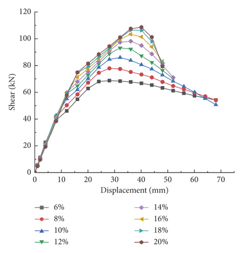
As can be seen in Figure 14, the axial load ratio has a greater effect on the thrust bearing capacity and ductility of this pier type. Also, it can be seen that the thrust bearing capacity of the bridge pier increased with the axial load ratio. The declining section of the skeleton curve of specimens with a low axial load ratio is gentler than that with a high axial load ratio. This fact indicates that the pier’s ductility performance decreases as the axial load ratio increases. Note that this inverse relation between ductility performance and axial load ratio is also indicated in the literature [31, 32]. Also, since the axial compression energy of the pier is appropriately reduced, the ductility performance of the pier is enhanced. Therefore, designers are recommended to appropriately reduce the axial compression ratio of such piers.
7. Conclusion
- (1)
The forcing process of the UHPC thin-walled short pier is divided into three stages, including elastic, crack development, and yielding stages. The test pier is seriously damaged at the plastic hinge area at the pier’s bottom, and the failure mode is “bending-shear failure mode”. Typical failure modes, including many horizontal and oblique cracks on the specimens, are observed.
- (2)
Introducing UHPC into the thin-walled short pier structure exhibits good seismic and energy dissipation performance. Also, the ductility coefficients of the specimens are all above three in value. The hysteresis curve of the specimens is relatively full, presenting a “shuttle-shaped” hysteresis curve. The equivalent viscous damping coefficients are all above 0.4, and the energy consumption is appropriate.
- (3)
The UHPC thin-walled short pier is 33.3% thinner than the RC pier. Also, the ductility increases by 53.36%, and the thrust stiffness is reduced by 23.73%. After raising the axial load ratio, the bearing capacity of the specimens increases by 26.7%. However, the horizontal force’s decreasing rate increases after the peak load. As a result, the axial load ratio appropriately decreases so that this pier type can obtain better ductility performance. In addition, ordinary stirrups have little effect on the bearing capacity and ductility of UHPC thin-walled short piers.
- (4)
The numerical results match quite well with the experimental data, indicating that the finite element model is feasible and reasonable. More importantly, this model can more intuitively reflect the internal failure behavior of UHPC thin-walled short piers.
The UHPC thin-walled short piers have lower thrust rigidity than traditional reinforced concrete piers. In addition, the seismic performance of traditional thin-walled short piers has been significantly improved.
Conflicts of Interest
The authors declare that they have no conflicts of interest.
Open Research
Data Availability
The data used to support the findings of this study are available from the corresponding author upon request.


