Spatial Numerical Simulation of Locally Corroded Steel Plate Girder with Various End Panels
Abstract
Field inspections indicate that corrosion damages steel bridge girders more at the ends as compared to the central region. Any significant loss of metal around the bearing region of the girder may cause an abrupt change of failure behavior and strength loss. The present numerical study is focused to evaluate the response of local corrosion damage at steel plate girder, with different end panels, that is, no end post, nonrigid, and rigid end post. Local corrosion damage was considered by reducing the bearings stiffener and adjacent web uniformly for a maximum damage depth of 100 mm with various corrosion damage levels (i.e., 75%, 50%, and 25%). The numerical analysis was performed on a computer package ABAQUS, using modified Riks analysis. A 4-node shell element (S4R) with reduced integration was used to simulate the model. The study concludes that local corrosion damage is more critical in nonrigid end post than in rigid end post. Furthermore, the steel girder with no end post is more susceptible to crippling failure due to local corrosion damage as compared to the other types of end post.
1. Introduction
Corrosion of steel structures is one of the most common phenomena. An aggressive environment and inadequate maintenance greatly aggravate the situation and may affect the performance of steel members, especially the capacity of steel plate girder in bending, shear, and bearing. The inadequate drainage of rainwater creates a water ponding effect around the bearing region of both through and nonthrough type of steel plate girder bridges that causes the corrosion, which may further invigorate due to the humid and hot climate [1, 2]. Such conditions promote the local corrosion damage nearby the bridge bearings area and leave most of the interior girder portion intact [3]. Figure 1 illustrates some typical local corrosion damage at steel plate girder ends, especially at bottom of the bearing stiffener and surrounding web. In a recent study, it was concluded that the less than 10% reduction of metal due to corrosions does not affect much the stiffness and ultimate strength of steel girder [4]. Furthermore, any severe corrosion damage may change the class of steel girder from noncompact to slender and may lead to the reduction of flexure capacity. It is quite important for designers to properly evaluate the available capacity and failure behavior of corroded steel girder so that decision regarding the replacement and retrofitting may be taken.
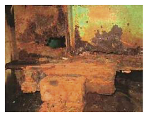
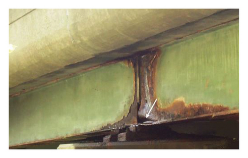
According to Alinia et al., [7] the ultimate capacity of the plate girder is improved by increasing the thickness of the end stiffener as it gives more fixity to the top flange; thus, any corrosion damage at bottom of the bearing stiffener may compromise the overall performance of steel girder. Khurram et al., [8] in their numerical study, evaluated the residual bearing capacity of steel plate girder affected by end panel corrosion damage. It was concluded that the anchorage of stiffener towards tension field action reduced considerably, and shear strength of plate girder is contributed by web alone if the thickness of bearing stiffener reduces more than 50%. Also, with the reduced stiffener thickness, the failure mode shifts from normal buckling to crippling, but the study was limited to the nonrigid end post only. In AISC Specification for Structural Steel Building [9], end panel design is only limited to nonrigid end conditions whereas Eurocode-3 [10] provides the design guidelines for three different types of end conditions as illustrated in Figure 2.
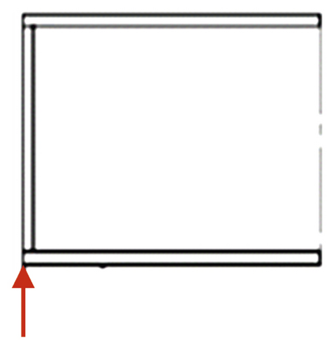
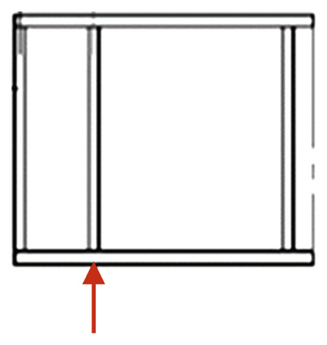
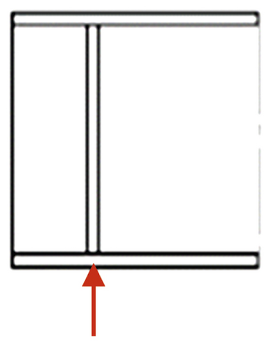
Estrada et al. [11] carried out a similar study on stainless steel plate girder and demonstrated that with end plates, the ultimate capacity of girder increases by supporting anchorage tension bands and giving extra flexural stiffness. The behavior of rigid and nonrigid plate girders also depends on the aspect ratio of the web panel. For a lower value of aspect ratio, there is a higher increase in the ultimate shear capacity of rigid end post. The dominating force in end panels is shear, and for a thin web-like in plate girder, this shear is mainly carried by the tension band anchored into the end post. Eurocode-3 [10] assumes that a rigid end post acts as both a bearing stiffener and as a short beam spanning between the flanges, resisting the reaction from the bearing and the longitudinal membrane forces. Two double-sided transverse stiffeners or a rolled section connected to the end of the plate may form a rigid end post. Although the effect of local corrosion on steel girder with nonrigid end has been evaluated previously [8], the performance of girder with no end post and rigid end post is not investigated yet. The present numerical study is focused to investigate the capacity reduction and failure mode of corroded steel girder end panel with various end conditions, that is, rigid end post, nonrigid end post, and with no end post.
2. Finite Element Modeling
2.1. Model Geometry and Material Properties
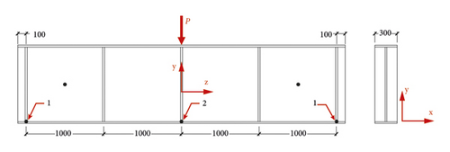
In order to attain uniform stress distribution and actual behavior of girder against the applied load, instead of the two-panel girder, researchers are using a four-panel plate girder in their numerical study [2, 7]. Therefore, in the present study, a 4-panel steel plate girder from the reference study [7] was modelled in a finite element (FE)-based computer package (i.e., ABAQUS) for the verification and extension of the numerical study. The selected girder is having the flange thickness (tf) = 9 mm, web thickness (tw) = 4 mm, and stiffener thickness (ts) = 8 mm. Flange and web size of the test girder were decided by keeping the tf/tw = 3 and bf/hw = 0.3 as per AASHTO guidelines for moderate flange thickness [12]. The complete geometry of the plate girder is shown in Figure 3. A mild steel of yield strength (Fy) equal to 345 MPa with perfectly plastic behavior and no strain hardening was used in the numerical study. The young modulus (E) and Poisson’s ratio (ν) of steel were considered as 210 GPa and 0.3, respectively.
2.2. Boundary Conditions and Analysis Type
To obtain a constant shear in web panels, simply supported boundary conditions have been applied. The supports corresponding to point 1 were released to translate in the z-direction and to rotate about the x-direction. The mid-point 2 was restrained to move in the z-direction (see Figure 2 for directions). A center point load p was applied at top flange of the plater girder. The force control analysis was performed by using a modified Riks analysis procedure. Riks method is usually preferred when there is a concern over material and geometric nonlinearity prior to buckling or unstable postbuckling response.
2.3. Initial Imperfections
There are two types of initial imperfections, namely, the structural imperfections and geometric imperfections, which affect the structural performance of thin-walled elements. These imperfections are induced in structural elements due to uneven heating and cooling processes during the making of the hot rolled section, and after welding of built-up sections. Furthermore, structural imperfections or residual stresses are also produced due to the cutting of steel elements during the fabrication process. These imperfections cause loss of stiffness and immature yielding. Past researchers suggest that residual stress must be considered, especially when thin-walled elements are subjected to compression, but they can be ignored when elements are subjected to bending or shear loadings [2, 13]. Due to this reason, residual stresses were not considered in the current FE study.
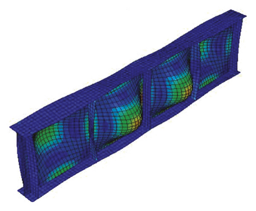
Guidelines of buckling design by the Japanese society of civil engineering (JSCE) [16] recommend a maximum out-of-plane deflection value of h/250, in case if actual imperfection data are not available. Since, in the present study, the web height (h) is 1000 mm, therefore, a value of 4 mm was used as the initial out-of-plane deflection at the center of the web panel. This average imperfection value is also very close to the value (i.e., 0.1β2 = 4.56) suggested by Smith et al. [15]. To introduce initial imperfection into the plate girder, first, a separate linear perturbation (eigenvalue) analysis was performed to extract various modes shapes of the plate girder model, and then, the mode shape as shown in Figure 4 was superimposing to the model geometry to induce the initial imperfections before running the analysis.
2.4. Meshing and Element Type
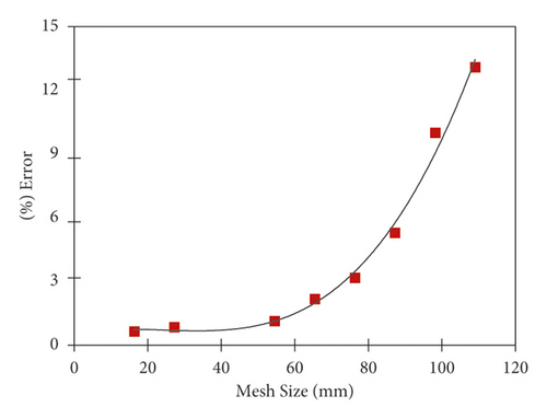
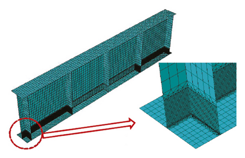
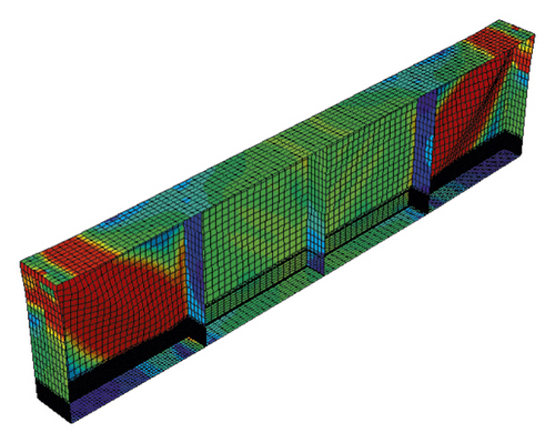
A general-purpose 4-node shell element (S4R) with reduced integration and hourglass controlled was used for the entire model. This element is having 6 degrees of freedom at each node and is fully capable of capturing a large strain, especially in the geometrically nonlinear analysis [17]. A mesh sensitivity analysis was performed to decide the element size. Figure 5 shows that the percentage error of ultimate load in comparison with the reference study [7] decreases with mesh size, and ultimate load almost remains constant for mesh size smaller than 50 mm. Thus, for a cost-effective solution, a maximum mesh size of 50 mm was adopted for the overall model, while, in the corroded zone, the mesh size was reduced to 2.5 mm (Figure 6) to grasp the large deformation.
2.5. Validation of Finite Element Model
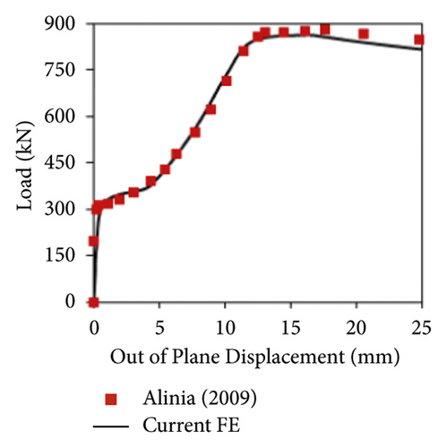
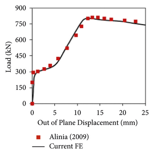
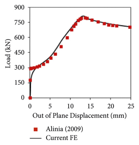
The FE model was verified by comparing the load-displacement curves with the reference study [7] as shown in Figure 7, where identical trends are quite evident. In numerical analysis, the load was applied at the midpoint, and vertical displacement was measured at point-2 as already highlighted in Figure 3. Furthermore, out-of-plane displacement was also measured at the center of exterior panels, which was also in agreement with the reference study (see Figure 8) for all three cases, that is, no end post, rigid end post, and nonrigid end post.
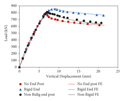
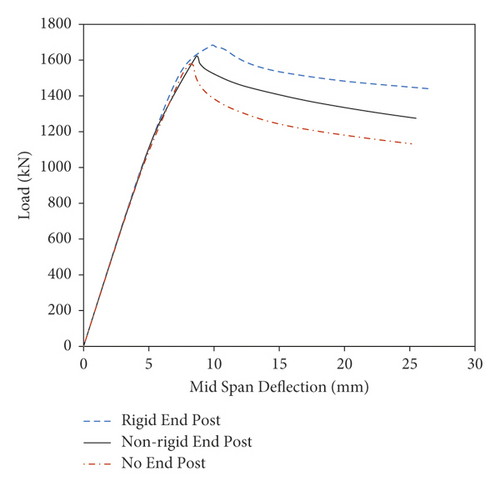
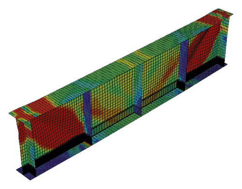
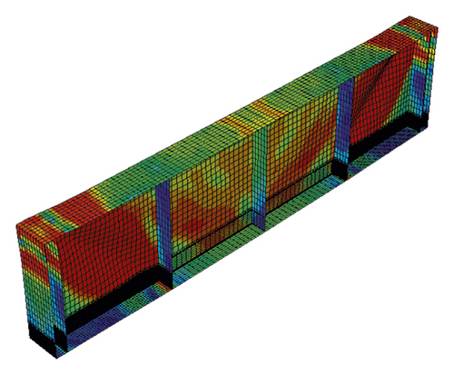
Almost, all design codes recommend a minimum value of wed thickness, that is, 6 mm by Japan Road Association (JRA) [18] and 10 mm by American Institute of Steel Construction (AISC) [9]. Therefore, for the extension of FE study, the minimum web thickness, tw, was used as 6 mm, and subsequently, tf and ts values were also modified to 18 mm and 12 mm, respectively, keeping the tf/tw = 3 and bf/hw = 0.3 to ensure the moderate type of flange condition. The width of the flange and height of the web were kept unchnaged (i.e., bf = 300 mm and hw = 1000 mm). The load versus vertical displacement curves and deformed shapes for three cases are shown in Figures 9 and 10. Table 1 shows the peak loads of three cases for both sets of plate thicknesses. It was found that both sets of plate thicknesses with identical end conditions are having almost similar peak load values when normalized with nonrigid end post case. Therefore, for the extension of the FE study, the girder with tw = 6 mm, ts = 12 mm, and tf = 18 mm was used as the reference model.
| End type | FE results for tw = 6 mm | FE results for tw = 4 mm | ||
|---|---|---|---|---|
| Ultimate load, P0 (kN) | Normalize load | Ultimate load, P0 (kN) | Normalize load | |
| Rigid end post | 1741.2 | 1.075 | 889.5 | 1.084 |
| Nonrigid end post | 1620.3 | 1 | 820.4 | 1 |
| No end post | 1575.1 | 0.972 | 796.4 | 0.971 |
2.6. Method of Study
- (1)
Plate girder with no end post
- (2)
Plate girder with nonrigid end post
- (3)
Plate girder with rigid end post
- (4)
Plate girder with nonrigid end post retrofitted by healthy end plate, thereby making it a rigid end post or rigid end post without exterior stiffener damage
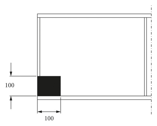
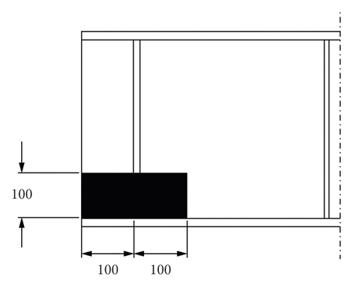
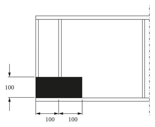
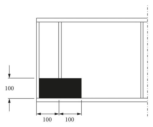
Earlier studies [8, 20] revealed that local web corrosion alone does not reduce the ultimate strength significantly, and capacity is mostly affected by the reduction of bearing stiffener thickness. Due to this reason in all cases, corrosion on the web is considered in combination with bearing stiffener.
3. Results and Discussion
3.1. FE Analysis of Corroded Model
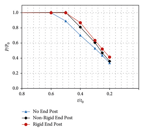
Figure 12 shows the reduction of the normalized ultimate load-carrying capacity (p/p0) with reduction of plate thickness for girders with nonrigid end post, rigid end post, and with no end post where p is the ultimate load-carrying capacity corresponding to any specific damage and p0 is the capacity of undamaged condition. Along y-axis, the normalized peak load with reference to the undamaged girder is shown with respect (along x-axis) to various residual thickness ratio (t/t0). Here, t is the remaining thickness, and t0 is the undamaged thickness of the plate. A typical value t/t0 = 0.5 represents that thicknesses of both web (tw) and flange (tf) are reduced to half with reference to their undamaged thickness. The normalized load-carrying results presented in Figures 12(a) and 12(b) exhibit no loss in ultimate capacity up to 50% reduction of metal due to corrosion, for the cases of girder with nonrigid and rigid end post, respectively. However, for the case of the girder with no end post, ultimate capacity starts dropping when the thickness is reduced by more than 40% (t/t0 < 0.6) as can be seen in Figure 12(c), that is, primarily due to less anchorage availability after elastic buckling of the web. The further decrease in web and stiffener thickness causes the capacity of the girder to decrease linearly against the reduction of residual thickness of the girder at the bearing region for all the damage depths, ranging from 20 mm to 100 mm. For all damage depths, the maximum reduction in thickness was considered as 80% (t/t0 = 0.2) to avoid nonconvergence issues for the case of complete loss of metal from bearing stiffener along with web, which is rarely observed in field inspection reports. Figure 12 also indicates that in all three damage cases, for any residual thickness ratio (t/t0), no significant reduction in capacity was observed when damage height is further increased from 40 mm to 100 mm (4% to 10% of girder height).
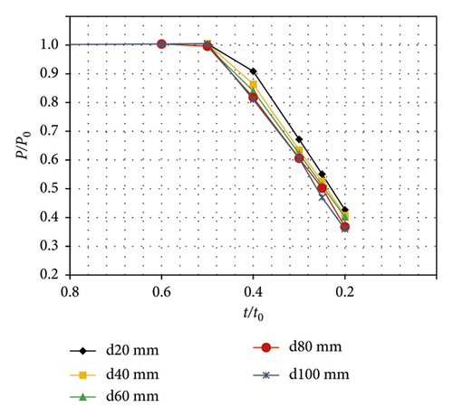
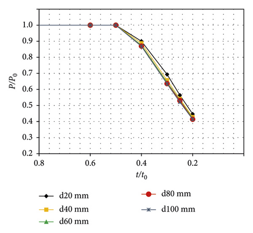
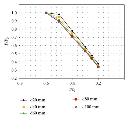
The comparison of capacity reduction of three cases for 100 mm damage height is shown in Figure 13. It is evident that girder with nonrigid and rigid end post has almost the same trend in reduction of capacity, but the reduction in capacity is more in girder with no end post for the same residual thickness ratio (t/t0). This large reduction in capacity for the cases of no end post is mainly attributed to the less anchorage at the junction of the bearing stiffener and bottom flange. As illustrated in Figure 14(a) for rigid end post, some portion of the web at both sides of the bearing stiffener also contributes to the column action, which increases the stability of the web in a lateral direction due to a larger moment of inertia. In the case of no end post (Figure 14(b)), the nonavailability of the web on one side of the bearing stiffener makes it less stable; thus, any local corrosion causes a larger reduction of capacity as compared with the other end types.
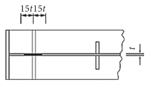
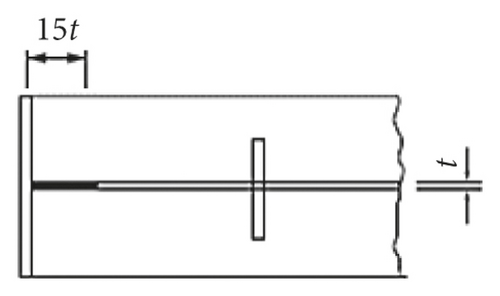
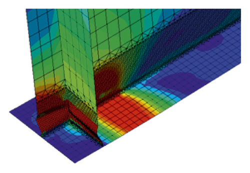
Numerical results exhibit that girder failure mode is not affected if the residual thickness is less than 50% (t/t0 < 0.5) for any damage height, and a normal failure mode as shown in Figure 10 is obtained. However, for the cases of nonrigid and rigid end post failure mode changes to crippling as shown in Figure 15(a) and Figure 15(b), respectively, if the web thickness is reduced by more than 50% (t/t0 < 0.5), regardless that the peak load is only reduced by 19%. In the case of no end post case, the crippling failure occurs (see Figure 15(c)) at a residual thickness (t/t0) value less than 0.6, even though the reduction in peak load is only 11%. This crippling failure causes the large deflection at supports and may destabilize the overall alignment of the bridges structure. This crushing at the bearing region occurs before the web achieves postbuckling strength, since the end post is designed both as a bearing stiffener to resist the reaction from bearing, and as a short beam spanning between the flanges to support membrane forces in the longitudinal direction. The local corrosion at bearing stiffener end and adjacent web region greater than 50% of original thickness changes the rigid (fixed) end condition to partially fixed or simply supported. This causes the premature yielding of material due to high-stress concentration corrosion damage zone and leads to crushing/crippling failure.
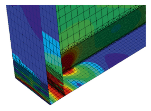
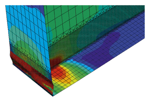
Furthermore, the contribution of end plate on the capacity of plate girder with the corroded nonrigid post as shown in Figure 11(b) was also checked in the FE study. For this purpose, corrosion damage is considered only at the bearing stiffener and surrounding web excluding the edge stiffening plate as illustrated in Figure 11(d). The peak load values for the damage cases shown in Figures 11(b) and 11(d) are summarized and compared in Table 2 for all damage heights (i.e., 20 mm, 40 mm, 60 mm, 80 mm, and 100 mm) with various corrosion damage (t/t0) values to check the effect of end stiffening plate. As it has already been concluded from Figure 13 that a corrosion damage less than the 50% of plate thickness does not affect the capacity of the girder, thus, the results of damage cases with a residual thickness of less than 50% (i.e., 40%, 30%, 25%, and 20%) are presented in Table 2. The results indicate an average improvement of approximately 12% capacity when a healthy end plate is welded with the corroded nonrigid end post case as shown in Figure 11(d). The enhancement in capacity was even more, that is, 19.84% and 22.71% for damage heights 80 mm and 100 mm with 20% residual thickness, respectively. This larger enhancement is mainly attributed to less stress concentration within a larger damage height, and consequently, failure mode also shifted from crushing to normal buckling due to a healthy end stiffening plate.
| Damage depth, d (mm) | Residual thickness, (t/to) | Peak Load, p0 (kN) | Capacity enhancement | |
|---|---|---|---|---|
| Nonrigid end post Figure 11(b) | With health end plate Figure 11(d) | |||
| 20 | 40% | 1472 | 1664 | 13.03% |
| 30% | 1088 | 1192 | 9.48% | |
| 25% | 892 | 979 | 9.69% | |
| 20% | 691 | 768 | 11.14% | |
| 40 | 40% | 1400 | 1518 | 8.48% |
| 30% | 1028 | 1123 | 9.19% | |
| 25% | 850 | 927 | 9.00% | |
| 20% | 660 | 731 | 10.88% | |
| 60 | 40% | 1362 | 1496 | 9.90% |
| 30% | 1008 | 1107 | 9.82% | |
| 25% | 829 | 908 | 9.57% | |
| 20% | 650 | 722 | 11.11% | |
| 80 | 40% | 1325 | 1488 | 12.35% |
| 30% | 982 | 1094 | 11.41% | |
| 25% | 814 | 905 | 11.21% | |
| 20% | 596 | 714 | 19.84% | |
| 100 | 40% | 1312 | 1487 | 13.32% |
| 30% | 981 | 1086 | 10.76% | |
| 25% | 761 | 877 | 15.29% | |
| 20% | 582 | 714 | 22.71% | |
3.2. Effect on Shear Strength Reduction
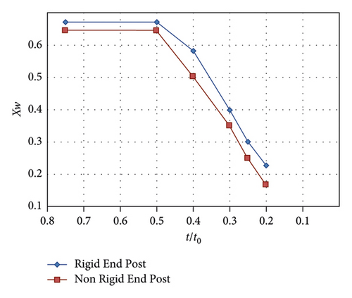
In (3) value of the factor, “c” is computed by (4). The M1 is the partial factor for resistance of members against instability, while ME and Mf are the maximum design moment and flange moment capacity, respectively. The recommended value of M1 is 1.1 by Eurocode-3 [10]. The factor Xw in (5) is the shear reduction factor, which depends on the end post conditions and the modified web slenderness. The change in the value of Xw has been worked out using back calculation to determine the effect of corrosion and type of end post on the factor Xw. Figure 16 shows the plot of sear reduction factor (Xw) versus residual thickness (t/t0), which indicates that the shear reduction factor remains unchanged until the residual thickness of 0.5 and Xw value drops from 0.67 to 0.58 for rigid end post and from 0.65 to 0.505 for nonrigid end post cases when t/t0 value is decreased from 0.5 to 0.4. This trend in reduction of Xw value almost remains linear with the decreases of t/t0 value, and larger reduction is induced in the nonrigid type of end post as compared with the rigid type.
4. Conclusion
The numerical results revealed that a rigid end post improves the load-carrying capacity, while girder with no end post has the lowest capacity. This is because the addition of end posts provides more fixity and anchorage to flange plates against bearing and membrane action, thus increasing the load-carrying capacity of the plate girder.
Corrosion in the bearing region starts playing role in minimizing the capacity when corrosion damage (t/t0) exceeds beyond a limiting value that is 50% for nonrigid and rigid end post. However, in a girder with no end post, this limiting value is the 40% thickness reduction. Any corrosion damage more than these limiting values changes the failure mode from normal web buckling to crushing or crippling at the bearing region, which may disturb the overall stability of the structural system. It is also evident that after a 50% reduction in thickness, the capacity of all three types of girders decreases linearly with decreasing thickness.
Change in ultimate strength (shear reduction factor, Xw) is larger in girder with no end post and least in girder with rigid end post. For a residual thickness of 20% (t/t0 = 0.2) and damage height of 100 mm, the capacity of girder drops to 41%, 36%, and 34% for rigid, nonrigid, and no end post, respectively.
This exterior end plate provides more fixity to the web and improves the capacity approximately by 12%. This enhancement in capacity is attributed to the extra anchorage provided by the exterior stiffening plate. In this case, crippling failure was also shifted from t/t0 value of 0.5 to 0.4. Thus, nonrigid end post may be transformed to rigid type by welding extra steel plate at the edge and nearby existing bearing stiffener.
Conflicts of Interest
The authors declare that they have no conflicts of interest.
Open Research
Data Availability
Data may be provided upon request.


