Camera Calibration for Long-Distance Photogrammetry Using Unmanned Aerial Vehicles
Abstract
The traditional target-dependent camera calibration method has been widely used in close-distance and small field of view scenes. However, in view of the field coordinate measurement in the large-scale monitoring area under the complex field environment, the standard target can hardly meet the requirements of covering most of the camera’s field of view. In view of the above problem, a stereo camera calibration method is studied, using the unmanned aerial vehicles (UAV) as feature points, combined with the high-precision position information measured by the real-time kinematic (RTK) positioning system it carries. The measured UAV coordinates are unified in World Geodetic System 1984 (WGS-84). Therefore, through several preset points, the measurement reference coordinate system which is the new world coordinate system we need can be established in any monitoring area, which greatly improves the flexibility of measurement. The experimental results show that the measurement accuracy of the proposed method can reach 0.5% in the monitoring area with a diameter of 100 m. The calibration method has a wide range of application and does not need the traditional standard target, and the measurement reference coordinate system can be established according to the actual needs. It is suitable for field spatial coordinate measurement in long-distance and complex terrain environment.
1. Introduction
Binocular stereo vision simulates human eye vision to realize the mapping from two-dimensional (2D) images to three-dimensional (3D) space and realizes the use of 3D information. At present, this method has been widely used in autonomous driving, robot navigation, virtual reality, and industrial production [1–6]. The process of solving this mapping relationship is called camera calibration, which involves some parameters, including both intrinsic and extrinsic parameters. Intrinsic parameters consist of principal points, focal lengths, and lens distortion. Extrinsic parameters include a rotation matrix and a translation vector between the two cameras.
Various effective calibration methods have been proposed, including traditional calibration methods, self-calibration methods, and camera calibration based on active vision. In the traditional calibration method, the intrinsic and extrinsic parameters of the camera are obtained by mathematical transformation of 3D coordinates and 2D image coordinates by presetting some targets. Faig [7] proposed an imaging model based on the optimization algorithm, which has a complex solution process and high initial value requirements. Abdel-Aziz and Karara [8] proposed the direct linear transformation (DLT) method, which ignored the effects of distortion and obtained unknown parameters of the equation by solving the linear equations. Tsai [9] proposed a two-step method based on radial constraint by combining optimization algorithm and direct linear transformation method on the basis of only considering radial distortion. Zhang [10] is best known for his flexible calibration method, in which he provided a good method for estimating the initial parameters of the camera by using the constraints of the homography between planes. The premise of the application of the above methods is to manufacture specific targets, such as checkerboard or circular targets, which is difficult to achieve in the field with a large field of view due to the size limitation. In response to the above problems, Faugeras et al. [11] and Maybank and Faugeras [12, 13] proposed a camera self-calibration method, which calibrated the camera by taking multiple images with distinct features and relative motion. However, this method had great limitations in sky, desert, sea, and other environments, and its robustness was poor and data reliability was insufficient. Similarly, Ma and Zhang [14–17] proposed a calibration method based on active vision, which required the camera to make specific movement and was not suitable for the occasion when the camera was fixed in the field with a large field of view. Besides, many scholars have proposed camera calibration methods in large field of view environment. For example, Kong et al. [18] proposed a method of camera calibration based on the Global Positioning System (GPS), which directly took the GPS instrument as the feature points, which limited the flexibility of the method in practical use. Xiao et al. [19] proposed a binocular 3D measurement system that uses a cross target with ring coded points. Shang et al. [20] proposed a large field of view calibration method in which the optical center and control point of the camera are close to the coplanar, which has many limitations. Sun et al. [21] proposed a baseline-based camera calibration method in which the calibration target must be randomly placed in the field of view several times. Wang et al. [22–24] proposed a stereo calibration method for out-of-focus cameras when acquiring images for long- and short-distance photogrammetry, which has high robustness and high accuracy. None of these methods enable precise and fast camera calibration at large field of view.
In this paper, a calibration method using the UAV with RTK as a high-precision mobile calibration target is proposed. This method does not need to manufacture large-scale calibration target, which reduces the requirement of calibration conditions, and is suitable for large scene field environment. In addition, by using the WGS-84 earth coordinate system as the intermediary, the measurement reference coordinate system can be flexibly converted to any desired position through several preset coordinate points, even if the position cannot be observed by the binocular cameras simultaneously, which is very suitable for some complex field scenes where the view is partially obscured by trees or hills. Experimental results show that the proposed method performs well in the monitoring area with a diameter of 50-100 m at the distance of 500-1000 m from the cameras.
The subsequent compositions of this article are as follows: Section 2 introduces the basic principles, Section 3 introduces the calibration process and experimental results, and Section 4 summarizes this article.
2. Calibration Theory
2.1. Camera Imaging Model
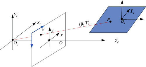
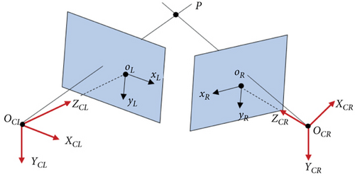
This paper focuses on where the camera is 500 m-1000 m away from the center of the monitoring area; therefore, the telephoto lens is used. Considering that the telephoto lens of the camera has very little distortion, the ideal pinhole imaging mode [25] is chosen to describe the mapping relationship between the object space and the image space, as is shown in Figure 1.
2.2. Coordinate System Conversion
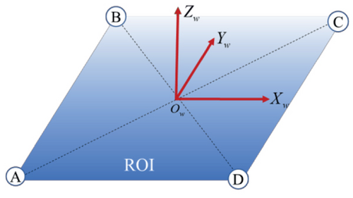
- (1)
Establishment of the preset coordinate system for a rectangular region of interest
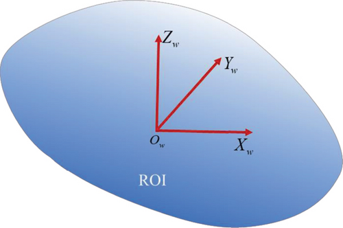
- (2)
Establishment of the preset coordinate system for a region of interest with a center point
Measure the latitude and longitude of a point as the origin Ow of the preset coordinates and convert the coordinate to the earth rectangular coordinate system under WGS-84. Without loss of generality, in the wild, due north is usually used as the Y-direction vector, due east is the X-direction vector, and the Z direction is perpendicular to them.
The preset coordinate system can be established by the above rules, as is shown in Figure 3. And the transformation vector between the preset coordinate system and the earth rectangular coordinate system is obtained as TE = Ow.
2.3. Single-Camera Calibration
The basic condition of parameter estimation is to find the matching relationship between image coordinates and 3D coordinates. In this paper, the centroid of the UAV is designated as the feature points in the left and right cameras, as shown in Figure 4.
2.4. Binocular Calibration
3. Experiments and Analysis
To verify the effectiveness of the proposed method, we set up a series of experiments. Five groups of camera-lens pairs were calibrated independently. Details of the camera-lens pairs are shown in Table 1.
| Group | Camera resolution | Camera model | Lens model | Pixel size (μm) | Focal length (mm) |
|---|---|---|---|---|---|
| 1 | 1920 × 1080 | Phantom V341 | Nikon 70-200 mm | 10 | 100 |
| 2 | 1024 × 1024 | Photron Nova s12 | Nikon 70-200 mm | 20 | 130 |
| 3 | 1280 × 800 | Phantom VEO 310 | Nikon 200-500 mm | 20 | 350 |
| 4 | 1280 × 800 | Phantom VEO 310 | Nikon 200-500 mm | 20 | 350 |
| 5 | 1920 × 1080 | Phantom VEO 440 | Nikon 70-200 mm | 10 | 170 |
In each group, identical camera-lens pairs were used to form a stereo camera, with the two cameras placed vertically, while monitoring an area 500-1000 meters away. The area covered by the cameras varies in diameter from 50 m to 100 m, depending on the focal lengths.
In the experiment, the UAV (DJI M300) with RTK (DJI RTK-2) was used as the high-precision mobile calibration target. The RTK master station was arranged on the ground, and the fuselage was equipped with the RTK slave station. In the range of 10 km, the measuring accuracy of the slave station can reach the order of centimeters [28], which is a satisfactory accuracy compared with the camera monitoring diameter of tens of meters.
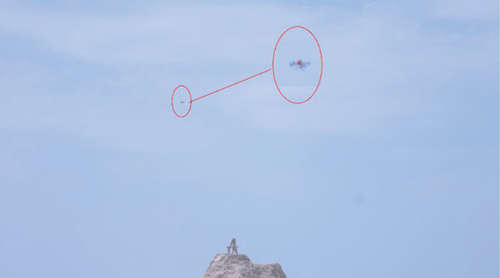
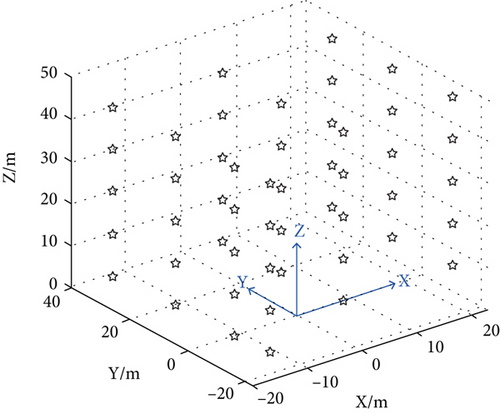
Control the UAV navigate over the monitoring area, and confirm that the UAV is in the field of view of the cameras. At 8 m, 16 m, 24 m, 32 m, and 40 m above the plane X-O-Y in the preset coordinate system, 10 points were suspended to record the GPS navigation coordinates and corresponding image coordinates of the UAV. Figure 6 illustrates the UAV images taken by two cameras. Convert the GPS coordinates to the preset coordinate system, and the position distribution of the UAV is shown in Figure 7.


3.1. Influence of the Feature Point Number on Calibration Results
As we know, the camera parameters can be correctly estimated only if there are at least six sets of 2D and 3D coordinates corresponding to each other. Adding a feature point means that the UAV needs to fly one more time, which will undoubtedly increase our workload. Therefore, it is meaningful to explore the appropriate number of feature points to reduce the work. Five independent experiments were carried out for the five camera-lens pairs described in Table 1.
In each experiment, 6, 10, and 40 UAV images (one image corresponds to a feature point position) were used to calibrate the stereo cameras. Then, the calibration results were used to reconstruct the space positions of another 10 UAVs. It is worth noting that the navigation coordinates measured by the GPS on the fuselage were used as the real space position of the UAV positions. Table 2 reveals the influence of different numbers of feature points on calibration results, in which the mean Euclidean distances of the reconstructed space positions and ideal ones of UAV are used to evaluate the accuracy of the results.
| Point number | Group 1 | Group 2 | Group 3 | Group 4 | Group 5 |
|---|---|---|---|---|---|
| 6 | 12.69 | 0.39 | 8.36 | 8.68 | 3.2 |
| 10 | 1.44 | 0.31 | 3.32 | 0.35 | 0.21 |
| 12 | 0.16 | 0.32 | 0.11 | 0.36 | 0.19 |
| 15 | 0.13 | 0.30 | 0.09 | 0.28 | 0.21 |
| 20 | 0.12 | 0.28 | 0.09 | 0.22 | 0.16 |
| 25 | 0.12 | 0.28 | 0.09 | 0.17 | 0.17 |
| 30 | 0.11 | 0.26 | 0.08 | 0.15 | 0.15 |
| 35 | 0.11 | 0.25 | 0.08 | 0.14 | 0.16 |
| 40 | 0.10 | 0.22 | 0.08 | 0.13 | 0.15 |
As is shown in Figure 8, the results of five experiments show that when the number of feature points is less than 12, the reconstruction errors decrease rapidly with the increase in the number of feature points. However, when the number of feature points is greater than 12, the impact of the number of feature points on the accuracy becomes smaller and the reconstruction accuracy only improves slightly. Therefore, 15~30 points are a good choice to balance efficiency and accuracy in practical applications.
3.2. Reconstruction Accuracy
The actual measurement accuracy is an important criterion to evaluate the calibration accuracy. Two markers were placed in the monitoring area of the cameras, and the actual distance between them can be measured by RTK. The same steps were used to calibrate the two cameras, and the coordinates of the two markers were reconstructed according to the calibration results, and then, the distance between them was calculated. Experiments were carried out on the five groups of camera-lens configurations, and the reconstruction errors are shown in Table 3.
| Group number | Measured length | Reconstruction length | Absolute errors | Relative errors |
|---|---|---|---|---|
| 1 | 24.25 | 24.36 | 0.11 | 0.45% |
| 2 | 32.83 | 32.77 | 0.06 | 0.18% |
| 3 | 46.60 | 46.48 | 0.12 | 0.26% |
| 4 | 46.60 | 46.50 | 0.10 | 0.21% |
| 5 | 30.00 | 29.95 | 0.05 | 0.17% |
It can be seen that the reconstruction results are stable in accuracy, the maximum absolute error is less than 0.12 m, and the relative error is less than 0.5%. This is satisfactory when the monitoring diameter ranges from 50 m to 100 m. The results show that the proposed method is accurate and flexible in calibrating cameras with large field of view in the wild.
4. Conclusion
In this paper, a camera calibration method for long-distance photogrammetry using unmanned aerial vehicles is studied. Instead of traditional targets, the GPS carried by UAV is used to obtain the spatial coordinate information, so as to complete camera calibration. This method overcomes the problem that standard target cannot cover most of the camera’s field of view and enhances the environmental adaptability. In addition, by using the WGS-84 coordinate system as the intermediary, the preset coordinate system can be established in any area of interest, improving the flexibility of measurement. Experimental results show that the absolute measurement error of the proposed method is less than 0.5% in the monitoring area with a diameter of 50-100 m and at the distance of 500-1000 m from the cameras.
Conflicts of Interest
The authors declare that there is no conflict of interest regarding the publication of this paper.
Open Research
Data Availability
The data used to support the findings of this study are available from the corresponding author upon request.


