[Retracted] Navigation and Positioning Analysis of Electric Inspection Robot Based on Improved SVM Algorithm
Abstract
In order to improve the accuracy of electric inspection robot navigation and positioning, an improved SVM algorithm was proposed to improve the accuracy of inspection. The research focuses on sensor calibration technology, lane line detection and robot positioning technology, obstacle detection and tracking technology, and substation road scene understanding technology. The results show that the radar measurement results have great fluctuation and deviation due to the existence of noise, but the results are smoother after EKF estimation. Secondly, the accuracy of the improved SVM classifier in this paper is much higher than that of the traditional method, and the improvement effect is obvious.
1. Introduction
Operation and maintenance is the key measure to ensure the safe and reliable operation of the power system. As a power system, the substation undertakes the important responsibility of transmitting power, transforming voltage and distributing power, and power distribution in the power system. The substation is geographically distributed in a wide area, with a large number and a wide variety; the operation state changes rapidly and needs to withstand the test of various climatic conditions of the operation environment. Its operation and maintenance account for a large proportion in the technology and management of the power grid company [1, 2]. Therefore, adopting new technologies and methods to improve the operation and maintenance level and efficiency of substation has always been the focus of power grid companies. For a long time, substation patrol inspection has been mainly completed manually. With the rapid development of power system, power grid companies are facing great pressure on patrol inspection [3, 4]. Therefore, the introduction of new technologies and methods to improve the operation and maintenance level and efficiency of substations has always been in the focus of energy network companies. For a long time now, substation inspections have been carried out mainly by hand. At a time when the energy system is developing rapidly, power grid companies are facing a huge workload [5]. In recent ten years, China has carried out the research and application of inspection robot and achieved gratifying results [6]. However, from a practical point of view, the current control robot system is still difficult to perform on its own [7]. Because the robot does not have the ability to understand the sensor information, even if it obtains the road environment information, it is unable to judge the road environment. Usually, it can only drive blindly according to the map and guide wire but can not adjust according to the real-time road conditions. Manual intervention is often required in the event of a problem, and the ability to work independently in an emergency is insufficient [8, 9]. In conclusion, the study of more intelligent energy control robots is based on the need to develop power systems on the one hand and the development of new technologies on the other. It can be said that the rapid development of energy control robot technology is beginning in the spring. Figure 1 shows a study of the positioning method of an electrically controlled robotic system based on an improved PSO + SVM algorithm.

2. Literature Review
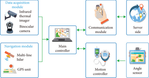
The research on the operation and maintenance robot of power system started early. About 30 years ago, an intelligent robot for substation inspection and transmission line inspection was developed [10]. In 1984, Japan’s Tokyo Electric Power Company and Mitsubishi group began to jointly study the intelligent robot. The company implanted the visual servo technology into the robot to enable it to carry out automatic positioning and automatic recognition of three-dimensional objects. The robot walks along the ground track and automatically obtains the data information in the station. So far, it has been developed to the third generation [11]. In 2003, Japanese experts put forward the idea of substation inspection robot and began to carry out simulation test [12]. In 2005, the first substation inspection robot was successfully developed by American experts. Its main task of inspection is to carry out infrared temperature measurement, and it has been put into production and use by power companies in the western United States [13]. In 2008, American scientists proposed a navigation system composed of inertial navigation and global positioning system, which can make the robot have continuous, real-time, and efficient navigation ability [14]. Muthugala et al. proposed a robot navigation method based on digital map and machine vision, and its effectiveness was proved by experiments. After that, experts and scholars from various countries began to study robot navigation methods, and many robot navigation methods have been proposed successively, such as RIFD positioning method, computer vision-based navigation method, and depth learning-based navigation method. The proposal of these methods has gradually improved the autonomous navigation ability of substation inspection robot, which is of great significance to the practicability and popularization of substation inspection robot [15]. The research on inspection robot in China started relatively late compared with foreign countries, but many achievements have been made in recent years [16, 17]. Around 2004, with the support of the 863 project during the Tenth Five-Year Plan period, many units, including Shandong University, Tsinghua University, and Shandong electric power academy, carried out in-depth research on transmission line inspection robots and substation inspection robots [17, 18]. In the field of transmission line inspection robot, Professor Wu Gongping’s team of Wuhan University has made great research achievements and important social impact. The inspection robot along the ground wire developed by the team can transform the shockproof hammer and suspension clamp on the ground wire into an unobstructed road structure, so as to realize the efficient and safe inspection of the inspection robot along the whole line [19]. The autonomous navigation technology of substation inspection robot can be divided into the following parts: sensor calibration technology, lane line detection technology, obstacle detection technology, road scene description, and understanding technology. The relationship between them and the system block diagram is shown in Figure 2. This paper will focus on these parts.

3. Research Methods
3.1. Lane Line Detection Based on Line Detection and Color Space Transformation
For the autonomous navigation of substation intelligent inspection robot, the most basic thing is to know its own local positioning [20]. Only by understanding the lane information can we obtain the position and direction of the robot relative to the lane. In the substation environment, most road scenes are structured roads. The so-called structured roads refer to standardized roads with clear lane signs, road boundaries, etc. [21]. The problem of how to extract accurate information from the outdoor environment, such as the amount of visual sensors, is often accompanied by a large amount of visual interference, which can not obtain accurate information from the outdoor environment.
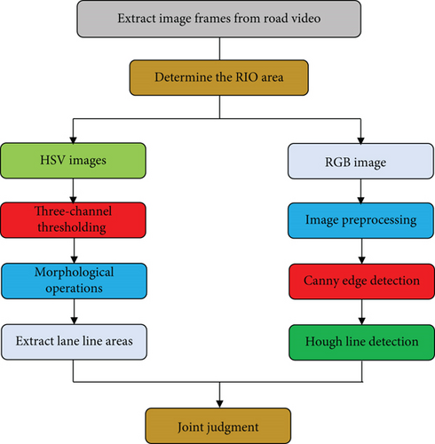
The road detection method studied in this paper is applied in the substation environment. At present, most of the substation roads are structured roads, the lane lines are yellow and clear, and most of the roads are straight roads [22]. Even if there are a few curves, for the moving robot, the curvature radius of the lane line not far from the camera is very small, and the lane line can be approximated as a straight line [23]. Therefore, this paper will use the combination of Hough line detection and color space transformation to detect the lane line in the substation road. The processing flow is shown in Figure 3. Firstly, each frame image of the camera is obtained and converted into RGB format. On the one hand, the image is preprocessed by binarization and noise reduction; then, Canny edge detection is carried out, and then, Hough transform is used for line detection. Through the screening of line segments, the candidate road edge collection is obtained. On the other hand, the RGB image is transformed into HSV color space image. By limiting the threshold of three HSV channels, the yellow lane line area is extracted, and the lane line area is appropriately expanded by morphological operation. Finally, the detection results of the two parts are fused to obtain a straight line that can divide the road area and nonroad area, and the lane line extraction test is carried out on the substation road pictures under different lighting conditions and different pavement environments with MATLAB.

3.2. Obstacle Tracking Based on Extended Kalman Filter
Extended Kalman filtering is the usage form of Kalman filtering in nonlinear systems, and the main idea is to find the best balance between the system state estimates at the next moment and the measurements obtained for state estimation. The fusion of the two is to continuously adjust a changing weight and finally obtain an infinitely close to the accurate value of the system at this moment. When the system is a linear model, the Kalman filter can give the optimal estimation, but in practical application, because the motion trajectory of the obstacle relative to the radar is nonlinear, and the radar measurement system itself is also nonlinear, it is necessary to approximate linearize the nonlinear system first and then use the Kalman filter for the optimal estimation [24]. This method is the extended Kalman filter method (EKF). The process of optimal estimation using extended Kalman filter is as follows:
3.3. Front Road Scene Recognition Based on SVM
- (1)
The working environment of intelligent robot is fixed, which is only the substation environment, and there is no need to distinguish different scenes or perceive the similarity of scenes
- (2)
The robot does not need to recognize the object in front. The obstacle in front is pedestrian or vehicle. For the robot, it can be attributed to the nonpassable area, and there is no need to know what the obstacle is. Therefore, the recognition of the road scene in front of the intelligent robot in the substation can be simplified to the state classification of the obstacles in front
- (3)
Because the application scenario of intelligent robot in substation is substation environment, it is difficult to obtain samples, it is not easy to collect a large number of images for training templates, and in practical application, the conditions for increasing a large number of training samples are also difficult to meet. Therefore, the classification problem of road environment in front of substation environment belongs to the classification problem of small samples
Of these, Gx (x, y) represents the horizontal gradient of the pixel, Gx (x, y) represents the vertical gradient, and H (x, y) represents the value of the point pixel. G (x, y) represents the size of the pixel point gradient, and α (x, y) represents the direction of the point gradient.
3.4. SVM Classification Experiment
The experimental process of classification is carried out on the schematic diagram of the road scene in front of the robot. The feature value extraction of the image, the training of the classifier, and the test of the training results are completed by MATLAB 2016b. The flow chart of the experiment is shown in Figure 4.

4. Result Analysis
4.1. Obstacle Tracking Experiment
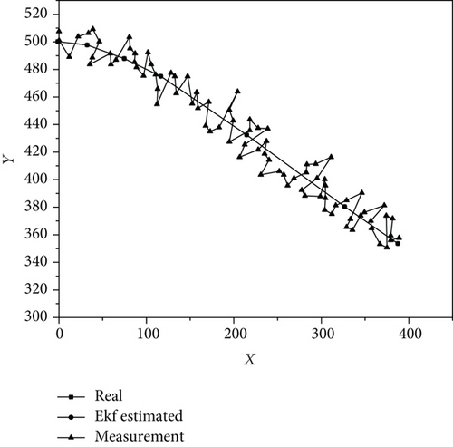
MATLAB is used to simulate an obstacle with nonlinear motion relative to the robot. The effectiveness of extended Kalman filter in obstacle tracking is verified by comparing the errors between the measured value, estimated value, and real value before and after adding extended Kalman filter. Figure 5 shows the relationship between the actual value, observed value, and EKF estimated value of obstacle motion. In Figure 5, “∗” represents the result of radar measurement, “+” represents the result after EKF estimation, and “-” represents the actual motion trajectory. It can be seen from the figure that due to the existence of noise, there are large fluctuations and deviations in the radar measurement result, and the result is smoother after EKF estimation.

4.2. SVM Classifier Test
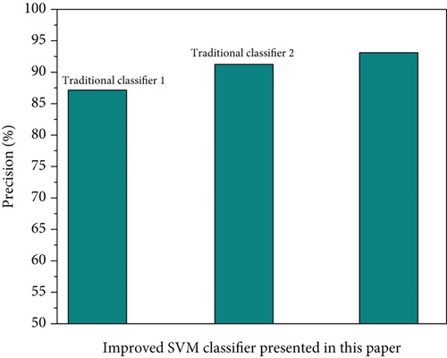
The feature vector extracted from the training set and the corresponding sample label are used as the input of SVM, and LIBSVM is used to train the semantic classification of images. Because different kernel functions will lead to different classification results of support vector machine for nonlinear SVM classification problem, the selection of kernel function has an important impact on the performance of support vector machine. Considering that Gaussian radial basis function (RBF kernel) has fewer parameters and is easy to calculate and RBF kernel is a kernel function with strong locality, high flexibility, and accuracy, and it is also the most widely used kernel function. This paper uses Gaussian radial basis function (RBF kernel) to train radial basis function SVM classifier. The specific test results are shown in Figure 6.

As shown in Figure 6, the accuracy of the improved SVM classifier in this article is much higher than that of the traditional method, and the effect of the improvement is obvious.
5. Conclusion
- (1)
A schematic diagram of the road ahead scene based on multisensor data fusion is proposed
- (2)
The front road scene recognition based on SVM is realized
To understand the front road map, an auxiliary vector machine (SVM) method is used to classify the front road map and define a schematic diagram. First, test the training package and the front road map diagram; then, write a function to extract and merge the hog feature and GLCM feature of the road scene diagram in front; then, the function is written and trained by using the extracted feature values of the front road scene, so as to obtain a multiclassification nonlinear SVM classifier, which can predict and classify the location of obstacles in the front road scene; finally, write a function to test the trained SVM classifier and visualize the test results. The results of the experiment show that the method can filter the position of obstacles in the front path with high accuracy, and the image recognition function is important to guide the further operation of the robot.
Conflicts of Interest
The authors declare that they have no conflicts of interest.
Open Research
Data Availability
The data used to support the findings of this study are available from the corresponding author upon request.


