Study on the Bearing Capacity of High-Cap Inclined Pile Foundations
Abstract
To analyze the bearing capacity of high-cap inclined pile foundations based on foundation design in practical engineering, finite element models of single cap foundations and multi-cap foundations are established. The influence of the inclination direction and angle of the inclined pile on the lateral displacement of the foundation and internal force of the pile body is investigated. The influence of uneven settlement on inclined pile foundations is examined by weakening the soil strength. This paper suggests that the lateral bearing capacity of a negatively inclined pile is better than that of a positively inclined pile. When the inclination angle of a negatively inclined pile changes within a certain range, it can significantly affect the lateral displacement of the pile body. Under uneven settlement, the change in the internal force of the inclined pile is larger than that of the vertical pile, the horizontal displacement difference of each bearing platform is small, and the vertical displacement is quite different.
1. Introduction
A pile foundation is suitable for building structures with an insufficient bearing capacity of shallow soil and high requirements for foundation displacement and bearing capacity. A high-pile cap foundation is a special pile foundation. The cap is located above the Earth’s surface. When the cap is subjected to horizontal load, it will produce a large lateral displacement [1]. For structures controlled by horizontal loads, the horizontal bearing capacity of pile foundations should be considered. A large-span transmission tower is a typical high-rise structure and wind-sensitive system. Horizontal load is an important factor in the design of pile group foundations of transmission towers and often has a controlling role. The horizontal bearing capacity of the foundation should be considered.
The vertical bearing capacity of a pile foundation can be easily adjusted by changing the pile diameter, pile length, and pile number [2]. Usually, the horizontal bearing capacity of a foundation is improved by increasing the pile diameter and pile spacing [3, 4]. Increasing the pile spacing and pile diameter will increase the construction cost of the cap, and improvement of the horizontal bearing capacity of the foundation is limited by the pile diameter and pile spacing. To explore a more economical and effective method for improving the horizontal bearing capacity of pile foundations, scholars worldwide have proposed setting inclined piles in pile group foundations to improve their horizontal bearing capacity [5, 6].
Dezi et al. [7] proposed a simplified numerical model for the dynamic analysis of inclined pile foundations. Compared with the stricter calculation method and fine finite element model, the calculation difficulty is reduced, and the loss of accuracy is not obvious. The calculation method proposed by Dezi et al. [7] simplifies the pile to an Euler–Bernoulli beam element, and the soil is composed of an infinite viscoelastic horizontal layer. The pile–soil interaction is considered by Green's elastic mechanics function. The pile–soil interaction of a 2 × 2 inclined group pile foundation under lateral load based on a scale test was explored by Goit et al. [8]. A semiempirical formula for predicting the soil reaction is proposed by analyzing the variation in the soil reaction along the pile depth. Carbonari et al. [9] selected the bridge foundation as the object and examined the influence mechanism of pile–soil-structure interactions with different inclined pile shapes and pile inclination angles. By considering the pile–soil interaction by the Green function, the stress distribution law and foundation filtering effect of inclined pile group foundations under earthquakes were analyzed. Álamo et al. [10] established the foundation of an inclined pile group to investigate its dynamic response law in heterogeneous foundations. By setting different soil profiles and soil parameters, the influence of different geological conditions on the impedance function of inclined piles and pile groups was investigated, and it was considered necessary to analyze inclined pile groups by selecting the soil layer that was consistent with the actual engineering situation.
Presently, scholars worldwide have focused on the bearing performance, dynamic response, and simplified calculation method of inclined pile group foundations under loads. There is a lack of research on the bearing performance of inclined piles, especially research on the bearing performance of inclined pile foundations under uneven settlement.
2. Model Establishment
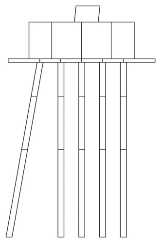
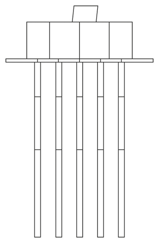
Based on a practical project in Brazil, this paper establishes a refined finite element model of high-pile cap-pile–soil. This project involves a river-crossing engineering section of an ultrahigh voltage transmission tower. The foundation is set at the river bank, and the shallow soil has insufficient bearing capacity and is easily scoured by water flow. The selected foundation type is a high pedestal, concrete-filled, steel tube pile foundation. The pile body is a concrete-filled, steel tube pile, and the pile length and steel pipe length are 10.3 m. Concrete is filled within 5.0 m above the steel tube, and the strength of concrete is equivalent to that of cap concrete. The lower part of the pile foundation is a hollow steel tube with a wall thickness of 12.7 mm. To resist the large horizontal force of the transmission tower, inclined piles are set in the pile group foundation to improve the lateral bearing capacity of the foundation. There are 22 concrete-filled, steel tubular piles under the cap, 5 of which are inclined piles. Figure 1 shows the left and front elevations of the single cap foundation. Geological survey reports provide standard penetration hammer counts for soils. In this paper, the elastic modulus of the soil is estimated by a standard penetration test (SPT). Sand can be estimated by the following formula: E 0.5 (N + 15); clay can be estimated by the following formula: E 0.6 (N + 5).
2.1. Element Type and Constitutive Model
The selection rationality of element and material constitutive determines the accuracy of numerical model calculation [11]. When the size of a component in one direction is much smaller than that in the other direction, the beam element, shell element, and other simplified elements can be utilized according to the characteristics of the structure. For components with the same dimension size, a solid element with high calculation accuracy can be applied. Solid elements are employed in the pile cap, pile body, coupling beam, and soil when establishing the pile group foundation model.
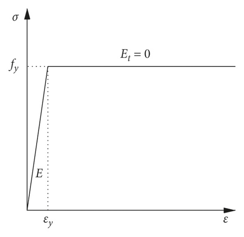
The appropriate constitutive model is selected according to the characteristics of different materials, and the ideal elastoplastic model is selected for plastic materials such as steel. The stress–strain curve of the model is shown in Figure 2. The ideal elastic–plastic constitutive model assumes that the material is completely elastic before the yield limit and completely plastic after the yield limit. A complete elastic model is adopted to simplify brittle materials such as concrete, and the plasticity and damage conditions of materials are not defined. Setting the soil constitutive model is the key to guaranteeing the accuracy of the calculation [12–14]. The Mohr–Coulomb model is a material constitutive model based on the shear strength theory of soil, which requires five parameters: elastic modulus, dilatancy angle, Poisson's ratio, internal friction angle, and cohesion. The latter two parameters are selected to define the yield conditions, and the model can better simulate the shear failure behavior of the excavated body.
The interaction between the pile and the soil is transmitted through contact, and the correct definition of the pile–soil interface is the key to ensuring the accuracy and reliability of the simulation results [15, 16]. General contact is set between the pile and the soil; tangential behavior of the contact surface is hard contact; and normal behavior is defined as penalty contact. The friction coefficient, which is determined according to the internal friction angle of the soil, is set to normal. The pile cap and pile body interact through a tie command.
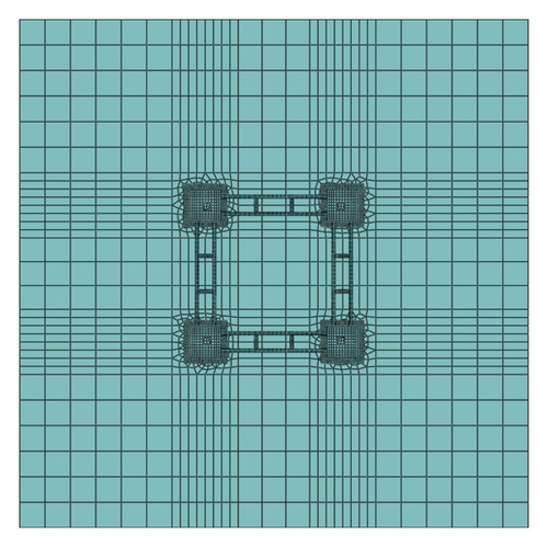
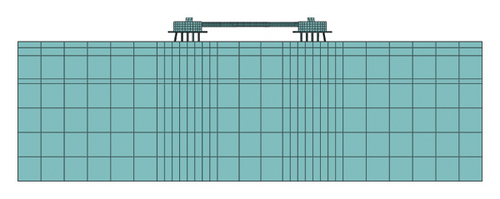
The calculation units of different sizes are divided according to the size and force complexity of different parts. Considering the calculation speed and calculation cost, the large components are divided into medium-sized grids, the grids are encrypted in the complex local stress region, and the small components are divided into small grids. A schematic of the grid division is shown in Figure 3.
2.2. Model Calibration
The correctness of the numerical model needs to be tested based on the existing calculation formula or related test results. Presently, there are no full-scale test data of large high-cap inclined pile group foundations, and it is difficult to verify the correctness of the model by test data [17]. In this paper, the single pile model, which adopts the same element type, constitutive relation, and contact condition as the pile group foundation model, is established. The vertical bearing capacity of a single pile is calculated by the formula, and the correctness of the model is verified by comparing the numerical calculation results with the formula calculation results [18].
The single pile model is shown in Figure 4, and the model setting is equivalent to that of the pile group foundation model. Figures 4(b)–4(d) show the overall stress cloud diagram of the model and the stress cloud diagram of each component. The stress of the pile is obviously greater than that of the soil, and the stress of the soil gradually increases from top to bottom. The soil around the pile is affected by extrusion and friction, and the stress of the soil layer around the pile is obviously greater than that of the other soil layers in the same plane. The stress distribution of the soil layer is consistent with the actual situation. When the vertical load is transferred downward along the pile, the vertical friction force provided by the pile wall increases with increasing pile depth, and the load transferred to the lower pile decreases. The pile stress gradually decreases from top to bottom, which is consistent with the simulation results.
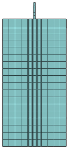
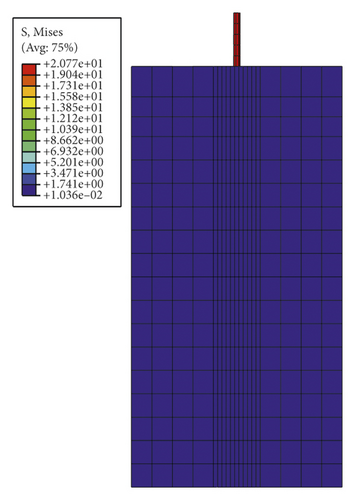
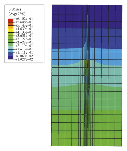
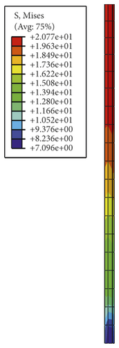
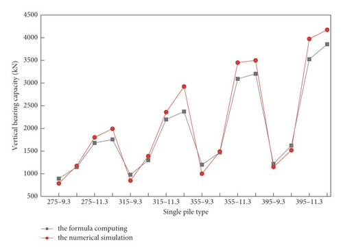
Figure 5 shows the comparison between the vertical bearing capacity of a single pile calculated by the formula and that of the numerical simulation. The single pile model 275–9.3 represents pile diameter of 275 mm and pile length of 9.3 m. The finite element calculation results of the vertical bearing capacity of single piles with different pile lengths and diameters are similar to those of formula mechanics; the bearing capacity of different single piles has the same variation trend; and the bearing capacity curves basically coincide. Therefore, the constitutive model, constraint conditions, boundary conditions, and interaction of soil selected for establishing the finite element model show agreement with the actual project, and the correctness and rationality of the model are verified.
3. Parametric Study of Inclined Pile Foundations
The large-span pile group foundation of the transmission tower investigated in this paper is composed of four caps, under which 18 vertical piles and 5 inclined piles are set. To control a single variable, a single cap model was established to study the influence of the inclined angle and direction of the pile on the bearing performance of the cap.
3.1. Vergence Direction
When the vertical pile is subjected to downward pressure, the lateral friction resistance and the bearing force at the bottom of the pile jointly resist vertical load. When the horizontal force is applied to the vertical pile, the pile wall compresses the surrounding soil to resist horizontal load. When the strength of the soil around the pile is insufficient or the horizontal force is large, the soil cannot provide enough horizontal resistance to the pile so that the horizontal displacement of the foundation exceeds the limit [19, 20].
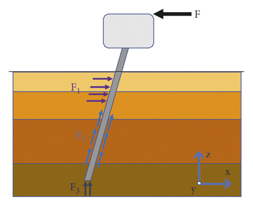
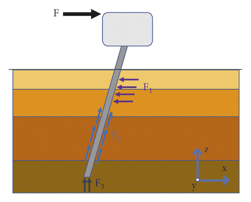
As shown in Figure 6(a), when the horizontal force direction is opposite to the inclined direction of the pile, it is referred to as a negative inclined pile. As shown in Figure 6(b), when the horizontal force direction is equivalent to the inclined direction of the pile, it is referred to as a positive inclined pile. Generally, the horizontal load and vertical load simultaneously act on the pile top, and the negatively inclined pile produces a horizontal component along the positive x direction under the action of the downward pressure load, which is opposite to the direction of horizontal load F, thereby reducing the horizontal load F acting on the pile body. After the downward load is applied to the positive inclined pile, the load component of the pile is consistent with the direction of the horizontal load, which increases the horizontal force acting on the pile.
Since the vertical loads on the four caps of the pile group foundation are different, the requirement of a single variable cannot be met, and the influence rule of the pile inclination direction on the horizontal bearing capacity of the foundation cannot be determined. Therefore, a single cap foundation was established, and both vertical and horizontal loads were applied to the cap to investigate the influence rule of the pile tilt direction on the horizontal bearing capacity of the foundation. The single cap model and grid division are shown in Figure 7.
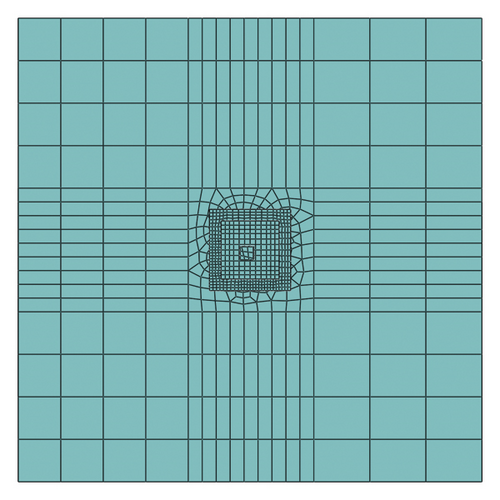
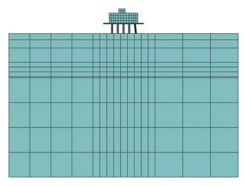
Figure 8 shows the displacements of the positive inclined pile, negative inclined pile, and vertical pile under load. The horizontal coordinate represents the amplitude of the downward pressure load. The red broken line, blue broken line, and black broken line represent the horizontal displacement of the positive inclined pile, negative inclined pile, and vertical pile, respectively. The horizontal displacement of the negative inclined pile is obviously smaller than that of the positive inclined pile and vertical pile, and the lateral bearing capacity of the negative inclined pile is better than that of the vertical pile and positive inclined pile. The vertical load can affect the lateral bearing capacity of the pile foundation. With an increase in vertical load, the lateral displacement of the vertical pile and negative inclined pile decreases, while that of the positive inclined pile increases. The top of the pile is 2.0 m above the ground; the displacement of the top of the negative inclined pile is slightly larger than that of the ground; and the displacement of the top of the positive inclined pile is obviously larger than that of the ground. The displacement difference between the pile top and the ground depends on the horizontal force acting on the pile top. With an increase in the horizontal load, the bending degree of the pile increases, and the displacement difference between the pile top and the ground increases.
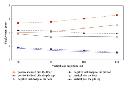
When the downward load and horizontal load simultaneously act, the negatively inclined pile generates a horizontal component along the inclined direction of the pile under the vertical load, which can offset part of the horizontal force. When the vertical displacement of the negative inclined pile is limited by the cap, the axial force along the inclined pile will be generated when the horizontal force acts on the pile top. The axial force can be decomposed into a vertical force and horizontal force. The horizontal component is opposite to the horizontal load, which further reduces the horizontal resultant force acting on the inclined pile. Under the action of vertical force, the horizontal component of the positive inclined pile is produced in the same direction as the horizontal force, which increases the horizontal force acting on the pile top. There is no horizontal component of the vertical pile under vertical force. Therefore, under the combined action of vertical and horizontal forces, the lateral bearing capacity of the negative inclined pile is the maximum, while that of the positive inclined pile is the minimum.
Figure 9 shows a comparison of the bending moments of piles in different inclined directions. The bending moment diagrams of the positive inclined pile, vertical pile, and negative inclined pile have the same shape, a circular arc; the maximum bending moment is located in different parts. The shape of the bending moment diagram is the same, which indicates that the soil has the same constraint behavior on the pile side, and the change in the inclined direction of the pile does not affect the interaction between the pile side and the soil. The bending moment values of different piles vary. The positive inclined pile has the largest bending moment value, and the negative inclined pile has the smallest bending moment value. The bending moment of the pile depends on the horizontal force acting on the pile top. The horizontal force of the positive inclined pile is the largest, so the bending moment is the largest. The positions of the maximum bending moments of the positive inclined pile, vertical pile, and negative inclined pile are −1.6 m, −1.1 m, and −0.9 m, respectively. With a decrease in the pile bending moment, the position of the maximum bending moment increases.
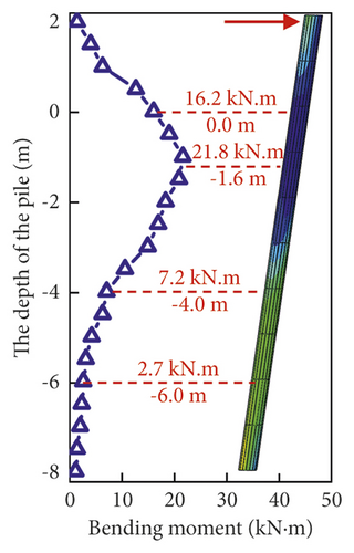
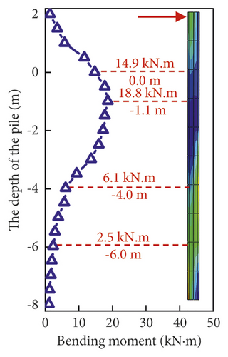
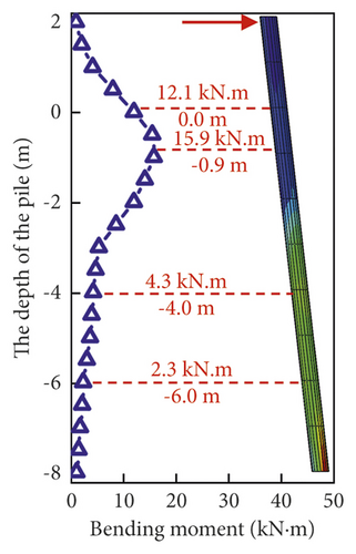
The inclined direction of the pile has a great influence on its lateral bearing capacity. The inclined pile indirectly changes the horizontal bearing capacity of the foundation by affecting the horizontal resultant force, which can be divided in two ways. For the first method, when the vertical force acts on the inclined pile, the pile interacts with the soil to produce the horizontal component. When the direction of the horizontal component is opposite to the direction of the horizontal force, the lateral bearing capacity of the foundation can be improved; when the direction is the same, the horizontal bearing capacity of the foundation will be reduced. For the second method, the pile top limits the vertical displacement. When the horizontal load acts on the pile top or cap, the inclined pile will produce the horizontal component, which increases or decreases the horizontal force acting on the pile.
As shown in Figure 9, the stress of the lower part of the pile is significantly greater than that of the upper part of the pile, which is caused by the pile structure. The upper part of the pile is filled with concrete, and the stiffness is large. The lower part of the pile is a hollow steel tube, and the stiffness is small. The stress in the lower part of the pile is greater than that in the upper part of the pile under the bending moment.
3.2. Pile Inclination Angle
Setting a negative inclined pile in a pile group foundation can reduce the lateral displacement, and the inclination of the pile will not only affect its vertical bearing capacity but also cause some difficulties in construction. Therefore, piles with inclination angles of 0°, 5°, and 10° are selected as the research objects, and the influence of the inclination of the pile body on the horizontal bearing capacity of the pile group foundation is analyzed through numerical simulation. In this study, the same depth of the pile is maintained. When the inclination angle of the pile is changed, the length of the pile is appropriately changed to ensure that the depth of the pile into the soil remains unchanged.
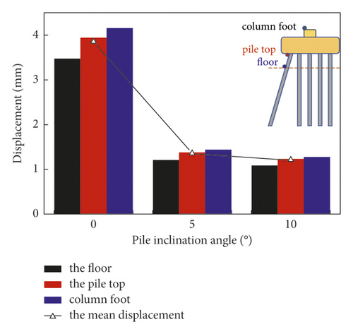
The inclined angle of the pile influences the horizontal bearing capacity of the foundation. Figure 10 shows a comparison of the foundation lateral displacement at different inclined angles of the pile body. The inclined angle 0° represents the vertical pile, and 5° and 10° are the negative inclined pile angles. The lateral displacement of vertical piles is obviously larger than that of negative piles with inclined angles of 5° and 10°. Setting negative piles can effectively reduce the lateral displacement of the foundation. The displacement of the 5° negatively inclined pile is smaller than that of the vertical pile, decreasing by 60.5%. The displacement of the 10° negatively inclined pile is smaller than that of the 5° negatively inclined pile, decreasing by 13.3%. The larger the inclination angle of the negative inclined pile, the smaller the horizontal displacement of the foundation. When the inclination angle is greater than 5°, a further increase in the inclination angle cannot effectively reduce the lateral displacement of the foundation. An excessively large inclined angle will weaken the vertical bearing capacity of the pile. To improve the lateral bearing capacity without reducing the vertical bearing capacity of the inclined pile, an inclined pile with an inclination greater than 10° should not be set.
4. Influence of Uneven Settlement on the Bearing Capacity of Inclined Pile Foundations
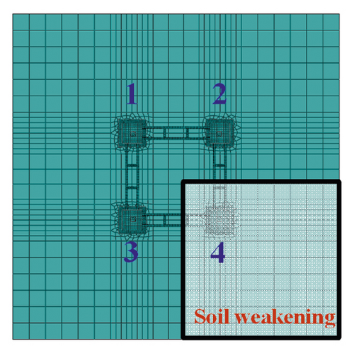
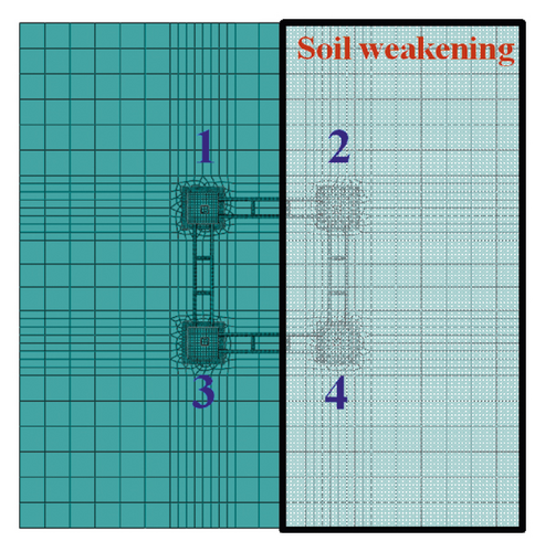
A full-scale numerical model of a transmission tower foundation was established to analyze the distribution of the internal force and displacement of an inclined pile foundation under the action of uneven settlement. The most unfavorable load is applied to the foundation, and the settlement of the foundation is caused by weakening the soil in different parts. To simulate the settlement condition of a single foundation, the strength of the soil under a single foundation is weakened, and the strength of the other soils is kept constant. To simulate the settlement condition of the double foundation, the strength of the soil under the double foundation is weakened, and the strength of the other soil remains constant. Different foundation settlement conditions are shown in Figure 11. In this study, the same depth of the pile is maintained. When the inclination angle of the pile is changed, the length of the pile is appropriately changed to ensure that the depth of the pile into the soil remains unchanged.
4.1. Analysis of Foundation Displacement
Figure 12 shows a comparison of the basic vertical displacement. The upward movement of the vertical displacement is positive, and the downward movement is negative. When the soil is uniform, the displacement of each cap is small. The maximum upward displacement is 1.7 mm, and the maximum downward displacement is 4.7 mm. When the soil under foundation No. 4 weakens, the maximum upward displacement is 21.1 mm, and the maximum downward displacement is 72.0 mm. The settlement of a single foundation significantly affects the vertical displacement of the whole foundation and changes the stress states of different caps, and the four caps interact through connecting beams. The soil under foundation No. 4 weakens; the cap is unloaded; and part of the load is transferred to other caps through connecting beams. The vertical displacement of cap No. 4 increases to 72.0 mm, and the vertical displacement of cap Nos. 1, 2, and 3 increases due to the increase in load transmitted from cap No. 4. In the case of double foundation settlement, the vertical displacement of foundations No. 2 and No. 4 obviously increases, while the vertical displacement of foundations No. 1 and No. 3 slightly increases. Part of the load of foundations No. 2 and No. 4 is transferred to foundations No. 1 and No. 3 through connecting beams, and the displacement of foundations No. 1 and No. 3 is slightly increased.
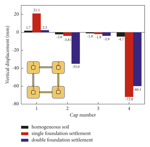
Figure 13 shows a comparison of the horizontal displacement of the cap; the direction of the horizontal force is also shown. When the soil is uniform, the minimum displacement of the cap is 3.3 mm and the maximum displacement is 4.8 mm. Due to the constraint of the beam, the horizontal displacement of the four caps is evenly distributed. When the single foundation is settled, the horizontal displacements of the four caps are larger than those of the uniform foundation. The distribution law of the horizontal displacements is equivalent to that of the uniform foundation. The maximum displacements appear in cap No. 1, and the minimum displacements appear in cap No. 4. In the case of double foundation settlement, the increase in the displacements of the four caps is obvious, and the distribution law of horizontal displacements is quite different from that in the case of uniform soil. The horizontal displacements of caps No. 2 and No. 4 are obviously larger than those of caps No. 1 and No. 3. When the double foundation is settled, half of the soil is weakened, and the ability of the foundation to bear the horizontal load is obviously weakened. As a result, the horizontal displacement of the whole foundation is obviously larger than the horizontal displacement of the foundation when the soil is uniform, and the constraint effect of the beam on the horizontal displacement of the foundation is weakened.
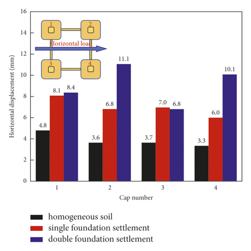
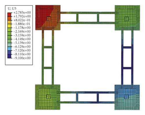
Figure 14 shows the displacement cloud diagram of the caps. The vertical displacements of the four caps are obviously different. The vertical integrity of the foundation is poor, and the ability of connecting beams to adjust the vertical displacements of the caps is limited. The lateral displacement of the whole foundation is uniform, the displacement difference between different caps is small, and the foundation beam has a strong ability to adjust the horizontal displacement.
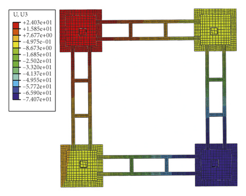
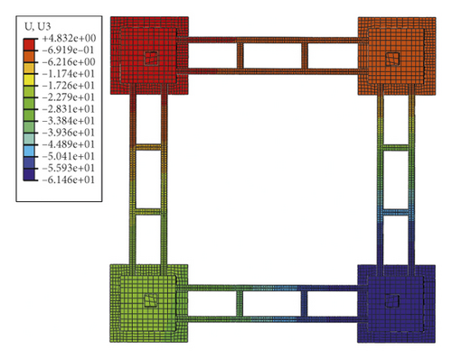
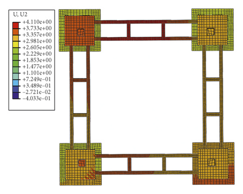
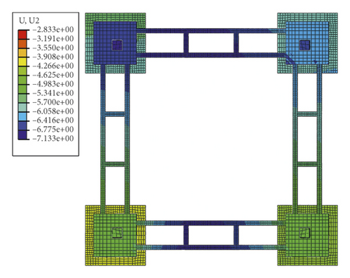
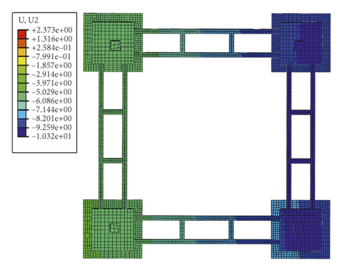
The displacement variation of inclined pile foundations under uneven settlement is analyzed by weakening the strength of the corresponding soil. The horizontal displacement of the pile group foundation increases with uneven settlement, but the difference in horizontal displacement between the four caps is small. The vertical displacement of the foundation with uneven settlement obviously increases, while the vertical displacement of the other three caps exhibits no obvious change.
4.2. Analysis of Foundation Internal Force
The uneven settlement of the foundation affects the displacement of the cap and the internal force of the pile foundation. To study the influence of uneven foundation settlement on the internal force of inclined piles, the maximum stress of piles under uniform soil, single foundation settlement, and double foundation settlement was compared. Figure 15 shows the maximum stress of different pile bodies under different caps.
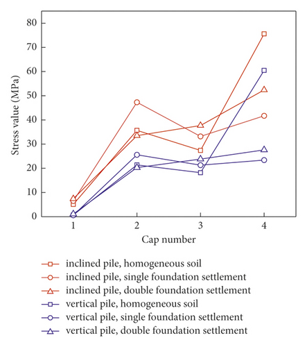
As shown in the figure, the stress of the inclined pile is greater than that of the vertical pile. The stress of the pile under cap No. 1 is the minimum; that of the pile under cap No. 4 is the maximum; and that of the pile under caps No. 2 and No. 3 is at the same level. When the soil is uniform, the difference in the maximum stress of the pile under different caps is caused by different loads acting on the caps. When the single foundation is settled, the stress of the inclined pile and vertical pile under cap No. 4 decreases, while the stress of the inclined pile under cap No. 2 and cap No. 3 obviously increases. The increase in the vertical pile stress is smaller than that of the inclined pile, and the pile stress under cap No. 1 exhibits no obvious change. When the double foundation is settled, the maximum stress of caps No. 2 and No. 4 slightly decreases, while the maximum stress of caps No. 1 and No. 3 increases. In conclusion, the stress variation of the inclined pile is obviously greater than that of the vertical pile when the foundation undergoes uneven settlement.
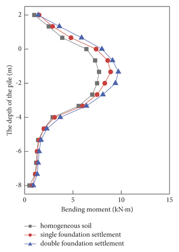
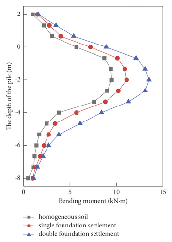
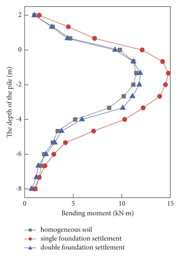
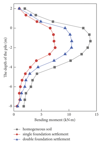
The bending moment diagram of the inclined pile under uneven settlement is shown in Figure 16. The bending moment of cap pile No. 1 is the smallest, while the bending moments of cap pile Nos. 2, 3, and 4 obviously change under different settlement conditions. Under the action of uneven settlement, the bending moment of cap pile No. 1 increases, but the variation is small. The bending moment of the inclined pile under cap No. 2 is the smallest when the soil is uniform; the foundation settlement increases the bending moment; and the influence of the double foundation settlement is greater than that of the single foundation settlement. The bending moment of the inclined pile under cap No. 3 is the largest when the single foundation is settled. The bending moment of pile No. 4 under the cap is the maximum when the soil is uniform, and when the soil layer is weakened, the bending moment of pile No. 4 decreases.
5. Conclusions
- (1)
The lateral displacement of the negatively inclined pile is the smallest, while that of the positively inclined pile is the largest under the combined action of horizontal load and downward load. Setting a negative inclined pile can improve the lateral bearing capacity of the foundation.
- (2)
The inclination angle of a negatively inclined pile has a significant influence on its lateral bearing capacity. When the inclination angle is less than 5°, the lateral bearing capacity obviously increases with increasing angle. When the inclination angle exceeds 5°, the lateral bearing capacity does not significantly increase with increasing angle.
- (3)
Under the action of uneven settlement, the difference in vertical displacement between each cap is obvious, but the difference in horizontal displacement is small. The basic type has good horizontal integrity but insufficient vertical integrity.
- (4)
The stress variation of the inclined pile is obviously greater than that of the vertical pile when the foundation settlement is uneven. The bending moment of the inclined pile decreases in weakened soil but increases in unweakened soil.
Conflicts of Interest
The authors declare that they have no conflicts of interest.
Acknowledgments
This research was financially supported by the Shandong Provincial Key Research and Development Program (under Award No. 2016GGX1040084).
Open Research
Data Availability
The data used to support the findings of this study are available from the corresponding author upon request.


