Study on the Vector Quadrilateral Isoparametric Shell Element with Shear Deformation
Abstract
Based on the linear superposition of the quadrilateral isoparametric membrane element and quadrilateral Mindlin plate element, basic vector formulas for the quadrilateral isoparametric shell element with the shear deformation is derived. Two different coordinate modes for updating the particle displacement and the element node internal force are put forward. The uniform numerical solution for an irregular quadrilateral element is realized by the isoparametric integral scheme along the element plane. Then, the bilinear elastoplastic constitutive of material is introduced into the vector finite shell element, and the nonlinear effect of the material is realized based on the integral method along the thickness. On this basis, the nonlinear calculation and analysis program of the quadrilateral isoparametric shell element is developed. Numerical example results show that the static and dynamic analysis, large deformation and large rotation analysis, and buckling analysis can all be well performed for the shell structures by the developed program, which verifies the validity of theoretical derivation and computer program.
1. Introduction
The shell structure is a two-dimensional element structure, which is widely used in engineering structures, including hyperbolic flat shells, spherical shells, cylindrical shells, and surface structures with complex surface structures and boundaries [1–5]. Under the action of external loading, the shell structure has both in-plane tensile deformation and out-of-plane bending deformation, which can be regarded as the linear superposition of membrane elements and plate elements.
The shell elements include planar shell elements and surface shell elements, and the former is relatively simple and has good precision. Green et al. [6] first adopted a triangular flat shell element and applied it to a shell structure of arbitrary shape. Zienkiewicz [7] proposed the analysis theory that combined membrane element and plate element to simulate planar shell element. Bathe and Ho [8] developed the basic theory for isoparametric thin shell element obtained from the surface of higher-order shape function, which was analyzed and compared with the calculation accuracy of thin shell element composed by linear superposition film element and the plate element. It was shown that the latter method had good accuracy and its theoretical formula was simple and easy to apply. Yang et al. [9] pointed out that by assuming the value of normal rotation stiffness to avoid stiffness matrix singularity, the obtained convergence result might be poor. It is suggested that the rotation degree of freedom should be considered separately as one of the degrees of freedom for the shell element to obtain more effective and accurate calculation results. In terms of the shear deformation of shell elements, there are some relevant literature studies. Wang et al. [10] proposed a simple first-order shear deformation shell theory (S-FSDST) for free and transient vibration analysis of composite laminated open cylindrical shells with general boundary conditions. Lezgy–Nazargah and Salahshuran [11] presented a novel mixed-field theory with a relatively low number of unknown variables for bending and vibration analysis of multilayered composite plates. Lezgy–Nazargah [12] developed a high-performance finite element model for bending and vibration analysis of thick plates based on the parametrized mixed variational principle. Lezgy–Nazargah and Meshkani [13] proposed a four-node quadrilateral partial mixed plate element with low degrees of freedom (dofs) for static and free vibration analysis of functionally graded material (FGM) plates rested on Winkler–Pasternak elastic foundations.
Vector Form Intrinsic Finite Element (VFIFE) is a new dynamic calculation analysis method based on particle mechanics and vector operation mode [14–16]. This method is based on the second law of motion of a particle and belongs to a class of discrete element method. It does not involve mathematical continuous function and has a simple theory and no iteration. By means of vector operation mode, the relations among variables such as force (moment), displacement, and acceleration are expressed by particles, while the numerical calculation results of multi-particle discretization approach the approximate value of the real unique solution, and each particle is calculated separately and cyclically step by step. Therefore, the VFIFE method is more convenient for analyzing the dynamic behavior of complex structures such as large deformation, large rotation, stability, collision, and fracture. At present, some research achievements have been made on two-dimensional plate and shell element of vector finite element. Wu et al. [17] studied the vector formula theory of triangular membrane element and applied it to large deformation and large rotation analysis of membrane structure. Wang et al. [18] studied the vector formula theory of triangular thin shell element and the treatment and application of elastic-plastic materials constitutive model. However, the existing literature of VFIFE mainly focuses on the research of triangular element, and there is no relevant study on the theory and application of quadrilateral isoparametric shell element, and the influence of shear deformation on thick shell is not involved.
In this paper, by linear superposition of quadrilateral isoparametric membrane element and quadrilateral Mindlin plate element, the basic vector formula of quadrilateral isoparametric shell element with shear deformation is derived firstly. Two different coordinate modes for solving particle displacement and internal force of element node and the integration of internal force for element node along element thickness and plane are then proposed. The bilinear elastoplastic material constitutive model is used to deal with the nonlinear effect of structure in vector calculation. On this basis, the nonlinear calculation and analysis program of quadrilateral isoparametric shell element is developed, and the validity of derived formulas and program codes is verified by analysis of typical examples.
2. Theory of Vector Quadrilateral Isoparametric Shell
The VFIFE method discretizes structure into two parts including mass particles and massless elements. And, the solving process includes three steps: the total displacement of particles, the pure deformation displacement of nodes, and the internal force of nodes. The shell element is superimposed of the quadrilateral membrane element and Mindlin plate element with shear deformation in this paper.
In this section, equation (1) is obtained by using the relevant formula in literature [19]. Equations (2)–(9) are the formulas of quadrilateral isoparametric shell element under the VFIFE theoretical framework derived in this paper, without reference to other literatures. Equations (10)–(32) are the relevant formulas of quadrilateral isoparametric shell element under the VFIFE theoretical framework derived with reference to the literature [19, 20], which belong to the original content, and have been cited in Sections 2.2 and 2.3, respectively.
2.1. Total Displacement of Particles
During each update substep, the central difference formula is used for numerical calculation, and the total particle displacement is gradually obtained through a loop substep update. For the quadrilateral isoparametric shell element in this paper, fint and in equation (1) are obtained from coordinate definition mode I, x and θ in equation (1) are obtained from coordinate definition mode II, which are described in Section 3.1.
2.2. Pure Deformation Displacement of Element Nodes
After projection method processing, the spatial quadrilateral element is transformed into the planar quadrilateral element, corresponding to the coordinate definition mode I (), where and are the coordinate vectors for projection points of element nodes i corresponding to the beginning and end of particle motion time substep, and are the angular coordinate vectors for projection points of element nodes i corresponding to the beginning and end of particle motion time substep, n and n′ are the mean normal vectors of the projection planes corresponding to the beginning and end of particle motion time substep. The total linear displacement vectors and total angular displacement vectors of element nodes i are, respectively, and .
The spatial motion for the projection plane (i.e., planar quadrilateral) includes rigid body translation, out-of-plane rigid body rotation, in-plane rigid body rotation, and pure deformation displacement. The specific derivation is similar to the triangle plate element theory in reference [19], and only the main derivation formulas are given in this paper.
2.3. Internal Force of Element Nodes
When solving the internal forces of element nodes, the VFIFE method transforms the spatial element problem into a planar element problem by defining the deformation coordinate system. The reference element node a is defined as the origin point in this section for the deformation coordinate system, and the axis is defined as the direction along the edge ab of the element, which results in and (i = a, b, c, d).
It is worth noting that the research topic of this paper is to develop a quadrilateral shell element considering shear deformation under the theoretical framework of the new analysis method VFIFE, rather than to develop a quadrilateral shell element considering shear deformation with better performance based on the traditional finite element method. VFIFE is a new analysis method based on particle motion, which has great advantages in structure discontinuity behavior, dynamic behavior, and other aspects (see Section 1 for details). However, there is no relevant literature on the quadrilateral shell element theory under the VFIFE method. In this paper, considering from the relatively simple quadrilateral shell element (that is, the linear superposition of the quadrilateral isoparametric membrane element and quadrilateral Mindlin plate element), so as to promote and improve the theoretical development and application of VFIFE, and give full play to the advantages of VFIFE method compared with the traditional FE method. Other refined and high-order shell element models considering shear deformation will be further studied in the future.
3. Key Problems and Corresponding Solutions in Numerical Calculation
3.1. Coordinate Definition Modes
The coordinate definition mode I refers to the coordinates of the element nodes when the pure deformation linear (angular) displacement and internal force (moment) of shell element nodes are solved from time t0 to t, so they need to be on the same reference plane. The four-node shell element is formed into a spatial quadrilateral after undergoing motion and deformation. The projection coordinates ( and ) for the element nodes on the reference planes which are perpendicular to the mean normal vector (n, n′) of the element and passing through the centroid points (C, C′) of the original element can be used as the coordinate definition mode I to realize the transformation of the spatial quadrilateral to the planar quadrilateral.
Coordinate definition mode II refers to the coordinates of each particle when the central difference formulas are applied for solving the particle motion equation (1), so it needs to be a unique value. The following two methods can be adopted: (1) the actual coordinates of the particle corresponding to the spatial quadrilateral after the element movement and deformation; (2) I element nodes corresponding to the same single particle in coordinate definition mode I obtained by plane projection do not coincide with each other, so the average coordinate value ( and ) of each element nodes corresponding to the same single particle in coordinate definition mode I can be taken as coordinate definition mode II, where k is the total number for that corresponding element nodes connected to each element by the same single particle.
3.2. Integral of Internal Forces for Element Nodes
4. Realization of Nonlinear Material Constitutive
The bilinear elastoplastic constitutive model is widely used in nonlinear analysis of structures considering the linear plastic hardening effect, which is used in this paper for theoretical derivation and numerical analysis.
4.1. Bilinear Elastoplastic Constitutive Model
This constitutive model is suitable for bilinear elastic-plastic materials. The case of Et = 0 corresponds to the ideal elastic-plastic model, and the case of σ0 ≫ σ corresponds to the linear elastic model.
4.2. Plastic Incremental Analysis Steps
-
Step 1: elastic prediction. The stress component σij,t and the equivalent plastic strain at the time t (i.e., at the beginning of time substep) and the incremental strain component from the time t to the time t + Δt (i.e., during the time substep) are given. Assuming that the time substep is completely elastic, the predicted elastic stress matrix σtr,t+Δt and the predicted plastic hardening parameter matrix at the time t + Δt are obtained.
-
Step 2: yield judgment. Substitute σtr,t+Δt and κtr,t+Δt at the time t + Δt into the yield condition equation (36), and judge whether it is an elastic or plastic incremental time substep according to the positive or negative of the predicted yield function ϕtr,t+Δt. If ϕtr,t+Δt > 0, it is a plastic time substep; Otherwise, it is an elastic time substep.
-
Step 3: plastic correction. If it is an elastic incremental time substep, then skip this step. If it is a plastic incremental time substep, the plastic flow factor increment Δλ is calculated on the basis of normal flow rule and dynamic yield criterion. The case of Δλ > 0 corresponds to the plastic incremental time substep, and the case of Δλ = 0 corresponds to the elastic incremental time substep.
-
Step 4: stress and strain updating. If it is an elastic incremental time substep, then σt+Δt = σtr,t+Δt. If it is a plastic incremental time substep, the stress and strain updating is carried out by Δλ. The updated variables include the equivalent plastic strain , the dynamic yield stress σd,t+Δt, the deviatoric stress component sij,t+Δt, the von Mises stress and the actual stress σt+Δt at the time t + Δt.
-
Step 5: solution of the elastic-plastic matrix. If it is an elastic time substep, there is no plastic matrix Dp. If it is a plastic time substep, the elastic-plastic matrix Dep needs to be solved. Through dynamic yield criterion and normal flow rule, the plastic flow factor increment dλ and plastic matrix Dp are obtained, and then Dep = De − Dp. Then, the internal forces (moments) of element nodes are solved by integral formulas.
5. Programming and Example Verification
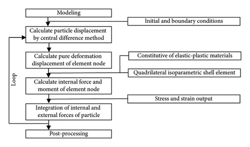
Based on the above-given theoretical formulas of vector quadrilateral isoparametric shell element with shear deformation, a computational analysis program is developed by Matlab software to realize the calculation and analysis of shell structure with shear deformation. The program implementation process is shown in Figure 1. Then, the rationality and practicability of derived formulas and program codes are verified by the following examples.
5.1. Static Bending of Annular Thick-Plate (Shear Effect along Thickness)
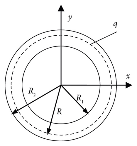
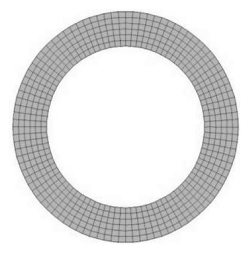
Taking an annular thick-plate with circular line load as an example [22], the influence of the shear effect along thickness for shell element on small bending deformation of thick plate structure is studied. Figure 2 shows the typical annular thick-plate structure, including the geometric model and mesh model. The inner radius of plate is R1 = 1.4 in, the outer radius of the plate is R2 = 2.0 in and the thickness of plate is ta = 0.5 in (corresponding width-thickness ratio is (R2 — R1)/ta = 1.2 < 5, that is, thick plate). The plate is placed horizontally and initially at rest. The boundary conditions for the inner circular edge and outer circular edge are respectively simply supported and free. The line loading q = 800 lb/in is loaded on the circular line at the radius R = 1.8 in of the annular thick-plate, and the static results are obtained by applying damping to eliminate the dynamic oscillation effect. The mass density is ρ = 0.1 lbs/in3, the Young modulus is E = 1.8 × 10⁷ lb/in2 and the ’Poisson’s ratio is υ = 0.3. The quadrilateral isoparametric shell element is used for numerical simulation. The time substep is h = 6.0 × 10⁻⁶ s and the damping parameter α = 2 × 10⁴.
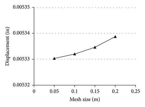
In order to investigate the influence of different mesh sizes on the VFIFE method in this paper, the mesh sizes l are set as 0.05 in, 0.10 in, and 0.20 in, respectively, for solving calculation. Figure 3 shows the comparison of vertical displacement convergence values of the outer-edge nodes with different mesh sizes. It can be seen that with the decrease of element mesh size, the vertical displacement decreases and the decreasing speed becomes slow. Therefore, the element mesh size l of 0.10 in is selected for in-depth analysis in the following, which has a relatively small calculation scale and high calculation accuracy.
In order to investigate the influence of different thicknesses on the VFIFE method in this paper, the shell thicknesses ta are set as 0.1∼1.5 in (the corresponding length-to-thickness L/ta is 6∼0.4), respectively, for solving calculation. Figure 4 shows the comparison of vertical displacement convergence values of the outer-edge nodes with different shell thicknesses. It can be seen that when ta ≥ 0.5 in (that is ta/l ≥ 5, which belongs to medium-thick shell, corresponding to L/ta = 1.2), the error between the VFIFE method and ANSYS calculation results is relatively small, and the calculation accuracy of the VFIFE method in this paper is improved with the increase of shell thickness. When ta < 0.5 (that is, belonging to thin-shell), the error between the VFIFE method and ANSYS calculation results is relatively large. When ta ≤ 0.2, the thick-shell element superimposed by the VFIFE method is not applicable, so there is no corresponding calculated value. Therefore, for the medium-thick shell element with ta/l ≥ 5, the VFIFE method has a high accuracy.
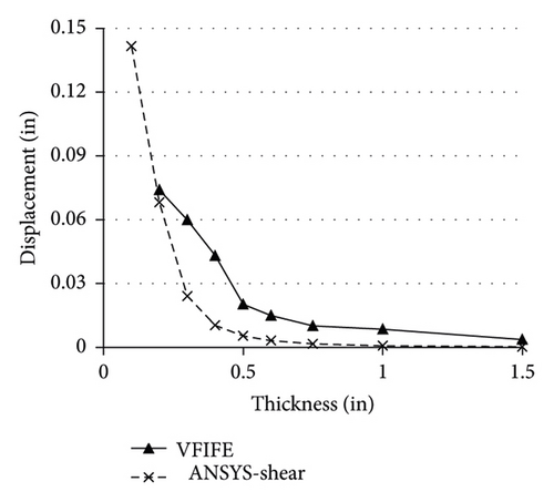
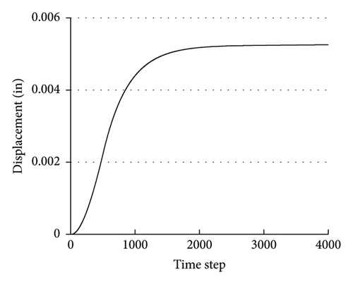
Figure 5 shows the computational convergence process for the vertical displacements of outer-edge nodes of the annular thick-plate with the mesh size l of 0.10 in. The result shows that it has good convergence and the vertical displacement convergence result is about 0.00533 in. Figure 6 shows the calculated results of the vertical displacements and von Mises stresses for radial nodes along the radial direction (corresponding to radial distance) of the annular thick-plate, respectively, and the comparison with ANSYS calculated results including that with shear effect (i.e., ANSYS-shear) and without shear effect (i.e., ANSYS-no-shear). Among them, I results of the cases for ANSYS-shear and ANSYS-non-shear are obtained by applying the shell43 element (considering Mindlin–Ressner first-order shear effect) and shell63 element (considering no shear effect), respectively.
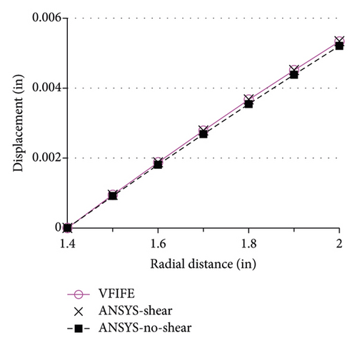
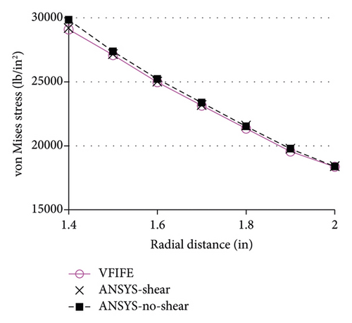
The result from Figure 6 shows that the vertical displacements of the outer circular edge node of the annular thick-plate calculated by the method of this paper (i.e., VFIFE), ANSYS-shear, and ANSYS-no-shear are 0.00533 in, 0.00534 in and 0.00521 in respectively. The errors of the displacement results of VFIFE are about 0.18% compared with the results of ANSYS-shear and about 2.31% compared with the results of ANSYS-no-shear considering the influence of shear deformation. The calculated result is basically consistent with the result in literature [22]. The case of results for von Mises stress is similar, that is, the maximum errors of the von Mises stress results of VFIFE are about 0.37% compared with the results of ANSYS-shear and about 2.58% compared with the results of ANSYS-no-shear. The calculated results of the proposed method in this paper (i.e., VFIFE method) are close to those of ANSYS-shear, which verifies the correctness and effectiveness of the VFIFE method. For the thick-plate structure, the shear effect has a certain influence, and the VFIFE method presented here has good accuracy for analyzing the thick-plate structure with shear deformation. With the increase of plate thickness, the shear effect cannot be ignored gradually.
The quadrilateral shell element of the VFIFE method in this paper is based on the linear superposition of the quadrilateral isoparametric membrane element and quadrilateral Mindlin isoparametric plate element, which is mainly applied for medium-thick shell structures. For thin shell structures, in addition to the low calculation accuracy, there is also a shear self-locking phenomenon. Due to the complexity of this problem, this paper did not make a detailed analysis and considered further research.
5.2. Dynamic Bending of Long Cantilever Plate (Large Displacement and Rotation)
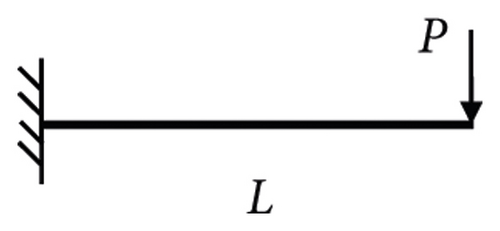
Taking a long cantilevered plate with a concentrated load at its cantilevered end as an example [23]. Figure 7 shows the typical cantilevered plate structure, including the geometric model and mesh model. The width of the plate is B = 0.2 m, the length of plate is L = 1.0 m and the thickness of plate is ta = 0.015 m. The plate is placed horizontally and initial at rest. The boundary conditions for one end and other end are, respectively, fixed and free cantilever. The concentrated load P = 100 kN is loaded on the midpoint of the cantilevered end for the plate. The ramp-platform dynamic loading mode is adopted, and the convergence value is achieved through damping. The mass density is ρ = 7850 kg/m3, the Young modulus is E = 201 GPa and the ’Poisson’s ratio is υ = 0.3. The quadrilateral isoparametric shell element is used for numerical simulation. The time substep is h = 2.0 × 10⁻⁶ s and the damping parameter α = 200.

The four cases of quadrilateral shell element (i.e., the superposition of quadrilateral membrane elements and Mindlin plate elements) in this paper with shear correction coefficients k = 5/6, 2/3, 1/3, 0 and the case of triangular shell element in literature [23] (i.e., the superposition of CST membrane element and DKT plate element) without shear deformation are considered for analysis and comparison. Figure 8 shows the vertical displacement-time curves for a long cantilevered plate at the central node of the free end, which shows good convergence under quasi-static calculation.
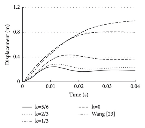
It can be observed from Figure 8 that the vertical displacement convergence values of the free end central node for the long cantilevered plate calculated by the VFIFE method of this paper with shear correction coefficients k = 5/6, 2/3, 1/3, and 0 are about 0.186 m, 0.227 m, 0.369 m, and 0.983 m, respectively, and that of literature [23] without shear deformation is 0.800 m. The vertical displacement at the central node for free end with k = 5/6 (i.e., general shear) is only about 19% and 23% of that with k = 0 (i.e., no shear) and that of literature [23], respectively. For long cantilever shell structures, the shear effect of shell element is extremely significant and cannot be ignored. In this case, the triangular shell element without shear deformation given in literature [23] is no longer applicable, and the quadrilateral isoparametric shell element with shear deformation given in this paper should be adopted.
In addition, the vertical displacement-time variation curves of the quadrilateral shell element with k = 0 (i.e., no shear) and the nonshear triangle shell element given in reference [23] are basically consistent before the time of 0.02 s, which also verifies the practicability of the proposed method (VFIFE) in a certain extent.
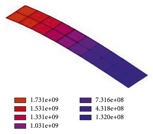
Figure 9 shows the displacement deformation diagrams of the long cantilever plate with shear correction coefficients k = 5/6, 2/3, 1/3, and 0 at the time of 0.04 s. It can be observed from Figure 9 that the long cantilever plate with a shear deformation effect presents a bending-shear bending form, which is a process of large displacement and large rotation. Taking the case of k = 5/6 as an example, Figure 10 shows the von Mises stress contours (MATLAB self-programming is used to draw) of the long cantilever plate at the time of 0.04 s. It turned out from Figure 10 that maximum stress appears in the root region of the long cantilever plate.


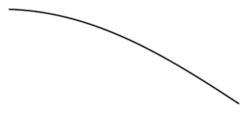

In the above, Figure 9 is not a curve, but a side view of the long cantilever plate with large displacement and rotation, which reflects the applicability of the VFIFE method in this paper under the condition of large deformation and rotation. As for the quantitative analysis of deformation under different shear coefficients, it has been described in Figure 8 and above.
5.3. Nonlinear Stability Analysis of Shallow Spherical Shell (Elastic-Plastic Material Constitutive)
Taking a jump instability of the shallow spherical shell with the central concentrated load as an example [24], the influence of elastic-plastic material constitutive for shell element on nonlinear stability is studied. Figure 11 shows the typical shallow spherical shell structure, including the geometric model and mesh model. The spherical radius of shell is R = 2.54 m, the projected side length of shell is L = 1.5698 m and the thickness of shell is ta = 99.45 m. The shell is placed horizontally and initial at rest. The boundary conditions are that four sides are simply supported. The concentrated load P is loaded on the central node of shell. The mass density is ρ = 2500 kg/m3, the Young modulus is E = 68.95 MPa and the Poisson’s ratio is υ = 0.3. The quadrilateral isoparametric shell element is used for numerical simulation. The time substep is h = 2.0 × 10⁻⁴ s and the damping parameter α = 20. The whole process of elastic-plastic instability of the shallow spherical shell is tracked by the displacement control method.
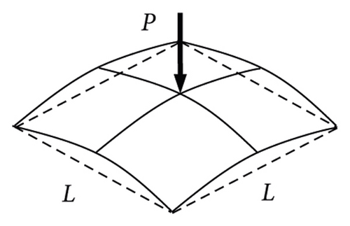
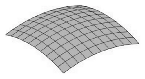
Figure 12 shows the concentrated load-vertical displacement curves for the central node of the shallow spherical shell. It can be observed that with the increases of the vertical displacement for the central nodes, there is an obvious load extreme point of the shallow spherical shell. After crossing the extreme point, the vertical displacement deformation turns over greatly and the load drops sharply. At this time, the structure cannot be used normally due to the excessive deformation, that is, the jump buckling occurs. After complete overturning, the load continues to increase with the increase of structural vertical displacement.
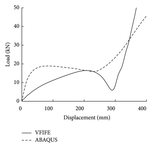
There are some differences in the load-displacement process between the VFIFE method of this paper and the ABAQUS method, but the overall changing trend is consistent, and the load extreme points are about the same. The maximum extreme point loading from the VFIFE method is about 16.45 kN when the vertical displacement is about 210 mm, and that from the ABAQUS method is about 18.76 kN, with an error of about 12.3%, which is relatively small. The calculation errors mainly come from the error of solving the jump instability problem and the number of shell elements. The error can be further reduced with the increase of the number of shell elements. As for the large difference between VFIFE and ABAQUS results in Figure 12, it may be related to the loading path and displacement accumulation effect of the buckling problem involving large deformation and abrupt deformation. However, the buckling extreme points are basically the same, which verifies the effectiveness of this method to some extent.
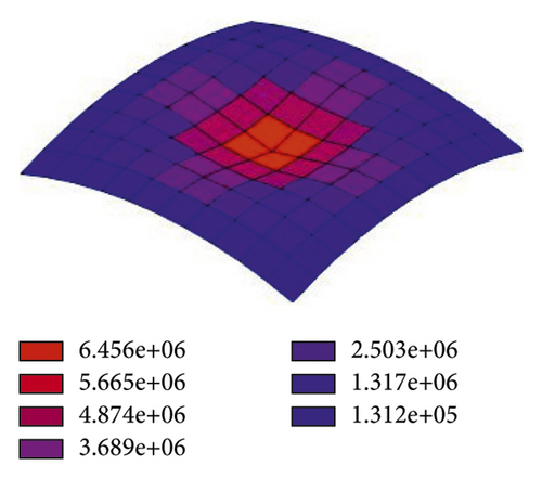
Figure 13 shows the von Mises stress contours (MATLAB self-programming is used to draw) of the shallow spherical shell when the maximum extreme point load (corresponding to the vertical displacement 210 mm) is reached by the VFIFE method. It can be observed from Figure 13 that the region near the central node is in a state of plastic hardening due to the concentrated load.
6. Conclusions
- (1)
Based on the linear superposition of the quadrilateral isoparametric membrane elements and the quadrilateral Mindlin plate elements, the basic vector formula of the quadrilateral isoparametric shell element with shear deformation is derived. Two different coordinate modes for updating the particle displacement and the element node internal force are proposed. The uniform solution of the irregular quadrilateral element is realized by the isoparametric integral scheme along the element plane.
- (2)
The bilinear elastoplastic constitutive model for the material is introduced into vector finite shell elements, and the nonlinear effect of the material is realized based on the integral method along the thickness of the element.
- (3)
Based on the established basic theory of quadrilateral isoparametric shell elements with vector finite element, the corresponding calculation, and analysis program is developed. Example analysis shows that the vector finite element program can obtain good computational accuracy in the static and dynamic analysis, large deformation, and large rotation analysis for shell structure, which verifies the rationality and practicability for derived formulas and program codes.
- (4)
VFIFE method is applied to the stability analysis for shell structures with double nonlinearity including geometric nonlinearity and material nonlinearity. By means of displacement control, the jump instability process of plate and shell structure can be obtained without special treatment, and the critical loading can be obtained, which reflects the advantages of this method in analyzing the stability problems of material with large deformation and rotation and elastic-plastic.
Conflicts of Interest
The authors declare that they have no conflicts of interest.
Acknowledgments
The research was supported by the Basic Public Research Project of Zhejiang Province (Grant nos. LGG22E080005 and LGG21E080004) and the Foundation of Zhejiang Provincial Key Laboratory of Space Structures (Grant no. 202101).
Open Research
Data Availability
The data used to support the findings of this study are included within the article.


