[Retracted] A Novel Maximum Flow Algorithm with Neural Network for Time-Varying Wastage Networks
Abstract
This paper introduces a time-varying wastage maximum flow problem (TWMFP) and proposes a time-flow neural network (TFNN) for solving the TWMFPs. The time-varying wastage maximum flow problem is concerned with finding the maximum flow in a network with time-varying arc capacities and additive flow losses on the arcs. This problem has multiple applications in transportation, communication, and financial network. For example, solving the maximum traffic flow of the transportation network and the maximum profit of the financial network. Unlike traditional neural network algorithms, the proposed TFNN does not require any training by means of its time-flow mechanism. The time-flow mechanism is realized by each active neuron sending pulses to its successor neurons. In order to maximize the network flow, the proposed TFNN can be divided into two parts: path-pulse neural networks (PPNNs) and subnet-flow neural networks (SFNN). PPNN is to generate two subnet sets (viz. with wastage arcs and without), and SFNN is to find the maximum flow value of each subnet. The subnet computing strategy of the proposed algorithm greatly improves the solution accuracy of TWMFPs. Theoretical analysis and experiments have proved the effectiveness of TFNN. The experiment results of the transportation network (viz. New York Road) show that the proposed TFNN has better performance (viz. error rate and computational time) compared to classical algorithms.
1. Introduction
The maximum flow problem (MFP) is a classical network optimization problem [1, 2], and it is also a general problem in vehicular networks [3], network optimization [4], social network [5, 6], and other fields. Ford and Fulkerson first solved the maximum flow problem using the labeling algorithm (viz. Ford-Fulkerson (FF) algorithm) [7]. Then, many improved labeling algorithms have been proposed for solving the maximum flow problems [8], such as Edmonds–Karp algorithm [9], and the Cai–Sha algorithm [10]. With the increasing complexity of networks, some intelligent algorithms have been used for solving the MFP, such as the genetic algorithm (GA) [11].
The time-varying wastage maximum flow problem is the maximum flow problem with time-varying arc capacities and additive flow losses on the arcs, which can be applied to intelligent transportation [12, 13], communication network [14], financial analysis [15, 16], and other fields. In financial networks, Eboli [17] has described the balance-sheet as a loss flow on the arc. The time-varying maximum flow problem (TMFP) [18, 19] and wastage maximum flow problem (WMFP) [20] have been investigated extensively. Li and Buzdalov et al. [21, 22] proposed their algorithms for solving the TMFPs. Cai [23] and Song [24] have researched different WMFPs. These existing algorithms were improved labeling algorithms [25]. While to the best of our knowledge, a question with regard to find the maximum flow value of time-varying wastage maximum flow problem remains open.
In this paper, we propose a novel neural network framework for solving the time-varying wastage maximum flow problem (TWMFP). The TWMFP is the maximum flow problem with time-varying arc capacities and additive flow losses on the arcs. The advantages of the proposed time-flow neural network (TFNN) are summarized as follows: first, different with general neural networks, the proposed TFNN does not require any training based on its time-flow mechanism. Second, compared with classical labeling algorithms, the proposed TFNN greatly improves the calculation speed based on its parallel computing feature. Third, unlike existing maximum flow algorithms, the unique group calculation idea of the proposed TFNN improves the accuracy for solving TWMFPs. In addition, the proposed TFNN can find an accurate solution to the general network maximum flow problems, such as MFP and TMFP.
The remainder of this paper is organized as follows: in Section 2, some basic concepts of TWMFP are introduced. In Section 3, the TFNN algorithm is developed and an example of a TWMFP is given. In Section 4, the experimental results are reported. And, Section 5 gives a conclusion to this paper.
2. Mathematical Formulation
The goal of the time-varying wastage maximum flow problem is to find the maximum flow from the departure node to the destination node within a predetermined period, where arc capacities change over time and flow on the arc may be consumed. Such problems introduced in this paper can be applied to fields such as intelligent transportation and financial analysis. For example, in a transportation network, road congestion during peak periods represents time-varying arc capacities and car accident emergency represents consumption/wastage on the arc.
Definition 1. [Wastage Network (WN)]. Let V be a set of network nodes, A = {(vi, vj)/vi, vj ∈ V} be a set of network arcs, C = {cij/(vi, vj) ∈ A} be a set of arc capacities, and W = {wij/(vi, vj) ∈ A} be a set of arc wastage, then the network G = (V, A, C, W) is defined as a wastage network.
Definition 2. [Time-Varying Wastage Network (TWN)]. Assume there is a wastage network G = (V, A, C, W), given a piecewise function C(ξ) = {Cij(ξi)/(vi, vj) ∈ A, ξi ∈ Tij} stands for a set of arc capacities, where ξ = (ξj/ξj = ξi + bij, (vi, vj) ∈ A), ξi denotes the depart time of node vi, bij represents the length of arc (vi, vj), means a set of time windows, and represent the earliest and latest depart times, z and Z denotes the index and number of time windows. Then, network G = (V, A, C(ξ), W) is a time-varying wastage network.
The arc lengths of time-varying wastage networks are set as a predetermined number δt. The arrival time of the destination node is calculated as follows:
Definition 3. [Feasible Flow]. Given a TWN G = (V, A, C(ξ), W), then the feasible flow Fij(ξ) of the arc (vi, vj) can be expressed as follows:
Considering the particularity of the departure node vs, then the feasible flow Fsy(ξ) can be calculated by the following equation:
3. Time-Flow Neural Network Algorithm Description
Generally, the labeling algorithms are used to find the solution of maximum flow problems. A disadvantage of these approaches is that they usually obtain large error rate solutions due to the time-varying and wastage in TWMFPs. This paper provides a better way to solve the time-varying wastage maximum flow problem.
In this section, the proposed TFNN algorithm will be described at first. And, then the construction of path-pulse neural networks (PPNNs) and subnet-flow neural networks (SFNNs) are depicted. To show the structure and algorithm of TFNN, the description of symbols are shown in Table 1.
| Symbols | Explanation |
|---|---|
| A pulse from neuron n to neuron i at time t1 | |
| wxi | Wastage of arc (vx, vi) |
| Uni | Wastage list of the path from neuron s to i, where n on the path |
| The z th time window of arc (vi, vj) | |
| Capacity from neuron i to neuron j at time window | |
| Bi | The relation neuron of neuron i |
| fzi | The flow of arc (vz, vi) |
| Go | The set of subnets without wastage arcs |
| Gw | The set of subnets with wastage arcs |
| Uix | Pulse information of arc (vi, vx) |
3.1. Description of TFNN
The underlying idea of using TFNN to solve TWMFP is that a neuron sends “preflows” (viz. pulses) to its successor neurons when the current neuron received pulses. With this new viewpoint, the proposed TFNN can reach a better solution of TWMFPs. There are two main parts in the design of TFNN, the first part is to find two subnet sets (viz. with wastage arcs and without) by path-pulse neural networks (PPNN), while the second part is to calculate the maximum flow of the subnets based on subnet-flow neural networks (SFNNs). The detailed steps of TFNN are shown in Algorithm 1.
-
Algorithm 1: Time-flow Neural Network (TFNN).
-
Input: Δt, T0, G.
-
Output: f∗./ ∗ The maximum flow. ∗/
- (1)
Set t = 0, f∗ = 0, Go = ∅, Gw = ∅.
- (2)
Do
- (3)
Generate subnet sets Go and Gw from G by PPNN.
- (4)
Set t = t + Δt.
- (5)
Until t > T0./ ∗ End step2 ∗/
- (6)
Update f∗ of all subnets in Go by SFNN.
- (7)
Update f∗ of all subnets in Gw by SFNN.
- (8)
Report the maximum flow f∗.
3.2. Description of PPNN
PPNN is used to generate two subnet sets (viz. with and without wastage arcs) through the following parts: first, initialize neurons by Step 1. Second, generate pulses from the departure neuron s at every time by Step 3. Third, update all nodes but s at every time by Step 4. Fourth, update subnet sets at every time by Steps 5–10. Finally, output subnet sets. The detailed steps of PPNN are shown in Algorithm 2.
-
Algorithm 2: Path-pulse Neural Networks (PPNN).
-
Input: Δt, G, t, Go, Gw.
-
Output: Go, Gw./ ∗ Subnet sets of G. ∗/
- (1)
Set
- (2)
Do
- (3)
- (4)
- (5)
If
- (6)
Set Go = Go ∪ R(Pnd).
- (7)
End If./ ∗ End step5 ∗/
- (8)
If
- (9)
Set Gw = Gw ∪ R(Pnd).
- (10)
End If./ ∗ End step8 ∗/
- (11)
Set t1 = t1 + Δt
- (12)
Until t1 > t./ ∗ End step2 ∗/
- (13)
Report two subnet sets Go and Gw.
All neurons in the PPNN will no longer generate pulses when the time limitation is reached. A general structure of a neuron in PPNN is shown in Figure 1.
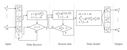
3.2.1. Input
The input part is used to receive pulses from its predecessor neurons.
3.2.2. Pulse Receiver
3.2.3. Neuron State
3.2.4. Pulse Sender
3.2.5. Output
The output part is used to send the pulse to its successor neurons.
3.3. Description of SFNN
SFNN is used to find the maximum flow of subnets through the following parts: first, initialize neurons by Step 1. Second, update all nodes, , and f∗ by Steps 2–7. Third, update D by Steps 8–10. Final, output the maximum flow. The detailed steps of SFNN are shown in Algorithm 3.
-
Algorithm 3: Subnet-flow Neural Networks (SFNNs).
-
Input: f∗, G′.
-
Output: f∗.
- (1)
Set , Bs = s, C = C′.
- (2)
Do
- (3)
Set D = 0, p = ∅, f(p) = 0.
- (4)
- (5)
Set p = Q(Pnd), w(p) = ∑(i, j)∈pwij, f(p) = F(Pnd)∗(1 − w(p))
- (6)
Set where (i, j) ∈ p.
- (7)
Set f∗ = f∗ + f(p).
- (8)
If M(i) of all nodes are not equal to 0.
- (9)
Set D = 1.
- (10)
End If./ ∗ End step8 ∗/
- (11)
Until D = = 1./ ∗ End step2 ∗/
- (12)
Report f∗.
Each neuron in SFNN will reserve the first pulse received in an iteration. A general structure of a neuron in subnet-flow neural networks is shown in Figure 2.
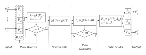
3.3.1. Input
The input part is used to receive pulses coming from its relational neurons.
3.3.2. Pulse Receiver
The value of Pni not equals ∅ means at least one pulse has reached at current neuron i at t.
3.3.3. Neuron State
3.3.4. Pulse Generator
3.3.5. Pulse Sender
3.3.6. Output
The output part is used to send pulses to its relational neurons.
3.4. An Example
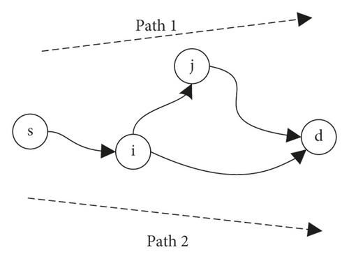
The detailed steps of TFNN for solving the TWMFPs are illustrated by an example. The topology and description of a time-varying wastage network are described as shown in Figure 3 and Table 2. The time limitation is T0 = 3.
| Node | Arc | Time window | Capacity | Wastage |
|---|---|---|---|---|
| s | s⟶i | [0,1) | 10 | 0 |
| [1,3] | 5 | 0 | ||
| i | i⟶j | [0,3] | 10 | 0 |
| i⟶d | [0,3] | 10 | 0.5 | |
| j | j⟶d | [0,3] | 10 | 0 |
-
First, find two subnet sets (viz. with wastage arcs Gw and without Go).
-
Go = {Path1, t = 0}, where Vo = {s, i, j, d}, Wo = {0,0,0}, Co = {10,10,10}.
-
Gw = {Path2, t = 0, and 1}, where Vw = {s, i, d}, Ww = {0,0.5}, Cw = {10,10} at t = 0, Cw = {5,10} at t = 1.
-
-
Second, calculate the maximum flow of the subnet.
-
The flow of Go is equal to f1 = 10 − 10∗0 = 10. Then, the capacity of arc (s, i) with depart time t = 0 is adjusted to 0. The flow of Path2 with depart time t = 0 is equal to 0. Therefore, the flow of Gw is equal to f2 = 5 − 5∗0.5 = 2.5.
-
To sum up, the maximum flow is f∗ = f1 + f2 = 12.5.
-
3.5. Time Complexity
Theorem 1. [Time Complexity of TFNN]. Given a TWN G, n represents the nodes number in G, m denotes the arcs number in G, T0 represents the time limitation, Δt means a unit time. Then, TFNN solves the time-varying wastage maximum flow problem in time, where int denotes the top of the integral function.
Proof. The overall PPNN consists of two parts. The time complexity of the first part (viz. Steps 1–5) depends on the PPNN algorithm and the second part (viz. Steps 6–8) depends on the SFNN algorithm.
For the PPNN algorithm, there is one loop and the worst time complexity is equal to o(5 + T0/Δt(3 + 12n + 2)) = o(5T0/Δt(12n + 5)). Based on the time complexity of PPNN, the time complexity of the first part of TFNN is equal to o(4 + T0/Δt(5 + T0/Δt(12n + 5) + 1)).
For the SFNN algorithm, there is one loop and the worst time complexity is equal to o(7 + T0/Δt(3 + 9n + 2 + m + 2)) = o(7 + T0/Δt(9n + m + 7)). According to the number of subnetworks is less then n, the time complexity of the second part of TFNN is equal to o(2n(7 + T0/Δt(9n + m + 7))).
To sum up, the time complexity of TFNN is equal to o(4 + T0/Δt(5 + T0/Δt(12n + 5) + 1) + 2n(7 + T0/Δt(9n + m + 7))) = o(4 + 14n + (18n2 + 2mn + 14n))T0/Δt + (12n + 5)T0/Δt2. Because there are at least two nodes (viz. n ≥ 2) and one arc (viz. m ≥ 1) in a network, we have. o(4 + 14n + (18n2 + 2mn + 14n)(T0/Δt) + (12n + 5)(T0/Δt2)) ≤ o((18n2 + 40n + 2mn + 9)(T0/Δt2)) ≤ o((43mn2)(T0/Δt2)).
According to Δt ≥ 1, the time complexity of TFNN can be simplified as follows: , here k denotes a constant.
Theorem 1 is proven.
4. Experiments
A large transportation network (viz. New York Road) is used to test the performance of the proposed TFNN algorithm. Time-varying and wastage components are added to some arcs in the network. The Ford–Fulkerson (FF) [26], genetic algorithm (GA) [22], Edmonds–Karp (EK) [10], and the Cai–Sha (CS) algorithm [11] will be used for experimental comparison with the proposed TFNN. There are 100 generations and 50 populations preset in the genetic algorithm [27].
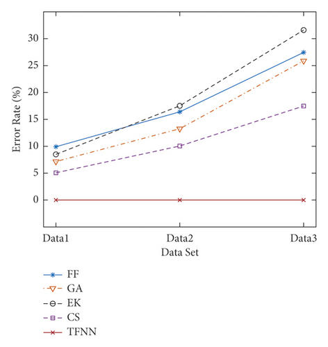
The error rate and computational time of these algorithms are compared as follows: the percentage deviation of the mean value (PDM) and the percentage deviation of the best value (PDB) are used as performance indexes (PI) to illustrate the error rate (ER) of different algorithms. PDM and PDB, respectively, are the mean and best value of ER for a set of networks. ER can be calculated as ER = (Fm − Fa)/Fm ∗100%, where Fm is the maximum flow among these algorithms and Fa is the flow value of each algorithm.We used 1000-node, 3000-node, and 5000-node networks for experiments and analyzed the error rate and computational time of the results. Table 3 reports the experimental results of TFNN, FF, GA, EK, and CS algorithms. Compared with other algorithms, the proposed TFNN always can find the best solutions in all cases. The error rate of other algorithms increases with the increase of nodes number. The PDM of other algorithms on Data3 all exceed 17.48% and the PDM of FF and EK are 27.45% and 31.61%, while TFNN is 0.00%. This is because both of FF and EK fail to take into time-varying components. GA adopts a random search mechanism. CS algorithm always finds the shortest path first, it reduces the solution accuracy. These results show that the proposed TFNN has better performance than existing algorithms (including FF, GA, EK, and CS). The tendency of the error rate of FF, GA, EK, CS, and the proposed TFNN algorithms are shown in Figure 4(a).
| Dataset | Nodes | Arcs | PI | FF | GA | EK | CS | TFNN |
|---|---|---|---|---|---|---|---|---|
| Data1 | 1000 | 2067 | PDM (%) | 9.911 | 7.159 | 8.491 | 5.067 | 0.00 |
| PDB (%) | 7.261 | 5.590 | 7.013 | 3.960 | 0.00 | |||
| Time (ms) | 49.13 | 1776 | 52.03 | 57.41 | 60.25 | |||
| Data2 | 3000 | 6106 | PDM (%) | 16.40 | 13.26 | 17.52 | 10.05 | 0.00 |
| PDB (%) | 13.51 | 10.94 | 13.19 | 8.108 | 0.00 | |||
| Time (ms) | 304.85 | 3574 | 317.49 | 436.53 | 240.93 | |||
| Data3 | 5000 | 10095 | PDM (%) | 27.45 | 25.88 | 31.61 | 17.48 | 0.00 |
| PDB (%) | 23.08 | 23.57 | 28.19 | 15.38 | 0.00 | |||
| Time (ms) | 955.64 | 6346 | 915.96 | 1213.96 | 582.21 | |||
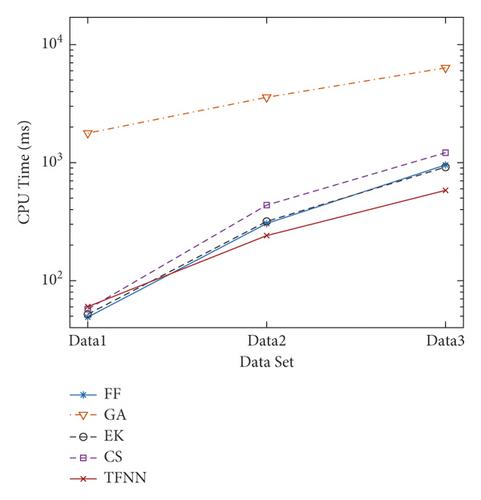
The calculation times of TFNN, FF, GA, EK, and CS algorithms are shown in Table 3. The computational time of the proposed TFNN is relatively short than other algorithms. First, GA requires more time to find a solution due to its pure random search mechanism. Second, as the number of nodes increases, the calculation time of TFNN is gradually better than the other three algorithms. The reason is that the complexity of the CS algorithm largely depends on the number of nodes, while the FF and EK algorithm will take more time to iterate as the number of nodes increases. The tendency of computational time of FF, GA, EK, CS, and the proposed TFNN algorithms are described in Figure 4(b).
5. Conclusions
In this research, we introduce the time-varying wastage maximum flow problem and propose the Time-flow Neural Network to solve the TWMFPs. The proposed TFNN does not require any training by means of a time-flow mechanism. Experimental results show that the proposed TFNN has better performance than traditional algorithms (including FF, EK, and CS) and intelligent algorithm (such as GA). The main advantages of TFNN are shown as follows.
First, compared with existing maximum flow algorithms, TFNN has higher accuracy when solving the TWMFPs. The proposed TFNN can obtain a larger flow due to its group calculation idea. The experiment results show that the error rate of TFNN is lower (17.48% lower than CS and 31.61% lower than EK) on a large network (5000 nodes and 10095 arcs).
Second, TFNN has a higher calculation speed based on its parallel computing feature. The experiment results show that the computational time of TFNN is 52% shorter than CS on a large network (5000 nodes and 10095 arcs).
In future research, more constraints can be considered when solving the time-varying wastage maximum flow problems. And, the neural network framework should be improved for the maximum flow problems under uncertain environments.
Conflicts of Interest
The authors declare that they have no conflicts of interest.
Acknowledgments
This work was supported in part by the National Science Foundation of China (Grant no. 61673295).
Open Research
Data Availability
The simulation experiment data used to support the findings of this study are available from the corresponding author upon request.


