DeepNet-Based 3D Visual Servoing Robotic Manipulation
Abstract
The fourth industrial revolution (industry 4.0) demands high-autonomy and intelligence robotic manipulators. The goal is to accomplish autonomous manipulation tasks without human interventions. However, visual pose estimation of target object in 3D space is one of the critical challenges for robot-object interaction. Incorporating the estimated pose into an autonomous manipulation control scheme is another challenge. In this paper, a deep-ConvNet algorithm is developed for object pose estimation. Then, it is integrated into a 3D visual servoing to achieve a long-range mobile manipulation task using a single camera setup. The proposed system integrates (1) deep-ConvNet training using only synthetic single images, (2) 6DOF object pose estimation as sensing feedback, and (3) autonomous long-range mobile manipulation control. The developed system consists of two main steps. First, a perception network trains on synthetic datasets and then efficiently generalizes to real-life environment without postrefinements. Second, the execution step takes the estimated pose to generate continuous translational and orientational joint velocities. The proposed system has been experimentally verified and discussed using the Husky mobile base and 6DOF UR5 manipulator. Experimental findings from simulations and real-world settings showed the efficiency of using synthetic datasets in mobile manipulation task.
1. Introduction
The use of autonomous mobile manipulators (AMM) has grown in many industries with developments enabling these systems to transport, organize, and process various assets. The two main industries commonly utilize this technology are manufacturing facilities and courier services that maintain a large inventory and benefit from efficient robots. To evolve the performance in autonomy and versatility, applied robots make use of several sensing technologies and control algorithms. Two key steps are typically required to carry out autonomous mobile manipulation tasks: firstly, perception step based on sensor-fusion methods which are used to estimate objects and perceive surroundings and secondly, sensing-based robotic motion control technique. This sensory network, however, leads to complex and expensive robotic systems [1, 2].
Recent studies have aimed to use only vision sensors to perceive the robot’s environment and gain adequate information about target objects [3]. However, preparation of training datasets requires effort and skills. As well as deep convolutional network training is computationally expensive and time-consuming [4]. Unlike 2D object detection, labeling 3D objects is a difficult task that requires a certain level of expertise. Although the use of synthetic datasets in the training of deep neural networks appeared and was discussed, it requires an endless supply of valuable prelabeled training datasets that are produced in a responsible manner [5]. Studies in [6] trained on synthetic and real-world dataset collections, including fine-tuning efforts. As a result, real-world applications of these methods are limited to structured backgrounds.
Another set of visual perception studies [7–9] requires complex vision-based setup to obtain the pose information of target objects. A stereo vision algorithm was proposed and tested in [3], using point cloud data from multiple stereo systems and utilizing iterative closest points. Vision-based mobile manipulator control was attempted in [10] using evaluation policy and requiring off-line training step. Minniti et al. in [11] addressed the whole-body control of mobile manipulator without considering tracking a target object. Much of the latest studies [12] developed a mobile manipulation system that included kinematic model where a path planner, however, is still required.
Nevertheless, none of the prior works has demonstrated a complete and continuous framework, for achieving 3D visual servoing (VS) in mobile manipulator, based on synthetic-trained deep neural network. A novel long-range mobile manipulation system is proposed and verified in this paper. This combines a visual perception network with a VS technique for controlling robot motion. The system presents an end-to-end framework of deep net-based 3D VS for sophisticated robotic manipulation task. The perception network constantly estimates the full pose of target object. It is worthwhile to mention that perception network entirely trains on synthetic (only RGB images) datasets and then successfully generalizes to real-world experiments without postprocessing. To provide autonomous manipulation task, outputs of perception network are directly fed to the VS control scheme.
The proposed system was successfully implemented in the simulation environment as well as in real-world settings using the 6 degrees of freedom (DOF) manipulator arm mounted on 2DOF differential drive mobile base. The use of synthetic datasets was applied in the context of 6DOF object pose estimation from a single image and executed robustly in 3D continuous AMM task. The findings have shown the physical capabilities of generalization to novel environments for the handling of light conditions and occlusion variations.
The remainder of the paper is organized as follows: Section 2 reviews the related recent works. Section 3 illustrates the modeling of the perception network for object detection and pose estimation, manipulator, and visual servoing model development. Section 4 shows experimentation results with discussions. Lastly, the conclusions are set out in Section 5.
2. Related Work
This section briefly highlights the recent methods of detecting and estimating object’s pose for manipulation applications. In the meantime, the control techniques of mobile manipulators are reviewed.
2.1. Target Pose Estimation for Visual Servoing Task
For robots to work effectively in unpredictable surroundings, they must understand the environment and possess adequate information on target objects, such as object pose information in the real world. Several studies use fiducial marker as a reference point for location of target objects in workspace. Additional research applied conventional computer vision approaches to determine the location of the target, for example, robot-object interaction tasks and model-based and feature-based methods. However, many inconveniences are associated with such methods such as limited background structure and poor performance with variations in lights and occlusion and require highly textured objects [13].
Robotic-object interaction task was conducted using convolution neural network (CNN). Recent studies were documented by Tekin et al. on single-shot network [9] and other networks such as BB8 [8] and SSD-6D [7]. Other works showed decent results and concentrated on problems like occlusions and different lighting conditions. The primary issue of training data, however, is how to generate an effective dataset. That presents sufficient variations for the deep net to learn from a wide range of lighting and pose conditions. Current labeling software like LabelFusion [14] has useful functionality for 3D object labelling. However, as far as we know, there is no simple and effective tool that helps to generate real-life training datasets, which can be used for 6DOF object pose estimation that is properly applied in mobile manipulation applications. Due to this difficulty, much of the existing studies presented systems for training deep network based on synthetic datasets [15, 16]. Fine-tuning efforts, however, are usually required to adjust the predictions in real-life settings and eliminate a problem known as reality gap. A recent solution was reported in [17], in which synthetic data is domain-randomized in nonrealistic manner. Training datasets include varieties of photorealistic and nonphotorealistic 3D backgrounds. This technique reinforces the deep net’s understanding and prepares it to deal with real-world scenarios. In this paper, our perception network trains on only synthetic dataset that was proved in [5] as the state-of-the-art, which also covers adequate possibilities of various poses in different environments, for instance, excessive lighting or occlusions.
2.2. Mobile Manipulator Control
The configuration of the mobile manipulator has advantage of mobility achieved by the mobile base and dexterity executed by the manipulator. This type of robot is more flexible for manufacturing than any other traditional approach such as stationary manipulators or limited automatic guided vehicles (AGV). Implementing visual servoing control scheme into long-range manipulation could be challenging when the robot continuously operates in 3D space based on only visual features. In pose-based visual servoing (PBVS) control techniques, the measurement of the target is happening by utilizing the vision feedback signal that controls the movement of robot until the visual error becomes zero. Researchers in [18] used a hybrid control scheme that used the strengths of image-based and pose-based VS methods for aerial manipulation. The polar and Cartesian parameters of a target object were used in conjunction with a Jacobian equation to compute the camera pose relative to the target object. This hybrid method also creates an effective system for a manipulator by resolving the rotational and translational issues during object tracking [19]. The mobile manipulator configuration typically creates redundant joints, which may inhibit its functionality. Several published studies have established the generic kinematic modeling of mobile manipulator configuration. Researchers in [20] proposed metaheuristic algorithms to enhance the kinematic solutions of mobile manipulator designs. A different configuration for a mobile manipulator system was introduced in [21]. The mobile base has two types of wheels, including directional and fixed. The system was tested in simulation environments but still lacked the guided vision-based method. The controller law in [22] used fuzzy logic to present the path planning of a mobile manipulator using vision-tracking system. However, soft computing concepts might propose approximation results, which may provide less accurate output. In [23], a multicamera VS system architecture was modeled and presented to control a robotic system where a target object is covered by multiple views. The controller could make different decisions since the pose estimation system was processed based on two perspectives. However, the computational level required longer processing times in addition to the limited applicable purposes.
The reviewed literature documented studies on mobile robots, while other publications focused on stationary robotic manipulators. However, combining the control techniques of mobile platforms and manipulators, both work based on deep nets, which is the challenge for new technologies. This work is, therefore, aimed at developing and testing a complete 3D visual servoing system that operates based on the collected feedback from a single camera. This paper focuses on an alternative solution that jointly uses DeepNet and PBVS to control an AMM system. This type of control scheme requires the pose parameters (related to a target object) that define the AMM robot’s final pose. The underlying idea is how to control the pose of the mobile manipulator robot with respect to the detected object by using visual features synthetically trained.
3. Full System Model Development
The proposed system architecture consists of three interconnected phases. First, a deep-ConvNet predicts 2D objects and produces 2D belief maps using a single RGB image. Second, a pose estimation algorithm utilizes the belief maps to recover translational and rotational pose of a target object. Finally, the execution step achieves the desired pose between the end-effector and the target object, by employing the estimated target’s pose and visual servoing control law. As the intention is to achieve 3D VS synthetically trained for the mobile manipulation system, we trained our system based on YCB images [24]. Figure 1 demonstrates the entire system architecture; the deep-ConvNet constantly detects and estimates the pose of the current object. The generated pose error stimulates the control law to send joint velocities and reduce the error by achieving a robot pose relative to the target object. The modeling of the system is illustrated in this section, which includes perception network and training, mobile manipulator robot kinematics, and the designing of VS control law based on the principle of Lyapunov.

3.1. Perception Network and Training Protocol
There are two main steps in the perception network: a deep-ConvNet step and a pose estimation step. Figure 2 depicts the deep-ConvNet architecture that trains directly on RGB image (w × h × 3), to predict the 2D key points of target object in the image. Transform-learning (of the first ten layers) is utilized as a feature extraction training step using VGG-19 model [25], pretrained on ImageNet [26]. Deep-ConvNet contains multiple stages of convolutional neural network that is preceded by the feature extraction step. The input to each stage involves image feature map of transform-learning and belief maps of the prior stage. Each stage of deep-ConvNet generates 2D belief maps of a target object.
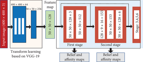
Feature dimensions are minimized from 512 to 128 by using two 3 × 3 convolutional neural layers. The feature map dimension-128 is the input to the first stage that contains three layers of 50 × 50 × 128 and one layer of 50 × 50 × 512. This stage produces belief map (50 × 50 × 9) and vector field (50 × 50 × 16) that both are fed to the next stage, in addition to the feature map (50 × 50 × 128). Similarly, the remaining stages (from 2 to 6) should have the same structure as the first stage. But the receiving dimension input (128 + 9 + 16 = 153) is different than a first stage. It is the output of the image feature map, as well as the belief map and vector field of the immediately preceding stage. In the remaining training stages, there are six layers of 50 × 50 × 128 which provide belief map and vector field. The final stage produces nine belief maps. Each one represents a vertex which will be at the end 8 projected vertices for 3D bounding box and one vertex for the centroid. To detect the object’s centroid, the network always seeks for local peaks from the belief maps. It uses the greedy algorithm that links the projected vertices to the indicated centroids.

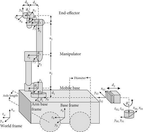
3.2. Mobile Manipulator Model Development
3.3. Mobile Manipulator Controller Design
The PBVS control aims to minimize the error between the desired and current end-effector pose, by regulating the movement of the robot through the determination of the necessary translational and rotational commands. Control law in PBVS is formulated from the perspective of the desired end-effector frame. The basis of the control law begins with Lyapunov’s proportional control scheme, . The proportional gain is denoted as k and the solution yields an exponential decrease of error. Visual servoing error is defined by the difference between the current image and camera parameters (s) and the desired image and camera parameters (sd), e(t) = s − sd.
4. Experiments and Discussion
In this section, the experiments were carried out in simulation and real-world settings. Several tests of autonomous 3D visual servoing were conducted to show the performance of the entire system. The perception network has shown effective and robust findings that are reliably enough to be implemented in long-range mobile manipulator model designed in the previous section. The anticipated behavior of the robot during the experiments involves navigating the robot to a desired destination and orienting towards a target object. The target is constantly detected, including its pose estimation information. The controller law (designed in the prior section) is implemented in the experimentations. Training step is not required in the implementation with VS of mobile manipulator. The mobile manipulator robot consists of 6DOF manipulator arm (UR5 developed by Universal Robots) mounted on top of differential mobile base (A200 Husky built by Clearpath Robotics).
4.1. Deep-Based 6DOF Object Pose Estimation
The perception network entirely trains on computer-generated images and then generalizes to operate on real-world experimentations. The single input image is processed to produce belief maps which hold probability values for each pixel of an image. Higher values represent target object location (target key points). Perception network detects the 2D key points associated with target object defining a bounding box. The detected key points include the centroid of target object with vertices of bounding box. A 3D pose of target object is retrieved by utilizing the estimated 2D key points, camera parameters, and target object dimensions. In contrary to recent researches [4, 8, 9] that demand complicated structure to segment target object in the input image, our deep-ConvNet utilizes the threshold local peaks in the belief maps. Then, a greedy algorithm links the projected vertices to the indicated centroids.
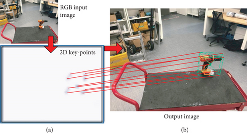
As a result of feature extraction step, feature map is fed to a series of CNNs that output belief map tensor. Each belief map tensor represents one of each 9 vertices of the 3D bounding boxes. Figure 5(a) illustrates the combination of the 9 vertices (of the final stage) that can form bounding box as well as one belief map for the centroid. 2D key points are produced from a single input image. Similarly, a process works simultaneously to infer multiple instances of objects. Figure 5(b) is the output image with the combined vertices and bounding box.
The entire execution time of the perception network is reported in Table 1, including object detection and pose estimation for different number of stages operating on seven different objects (drill, mug, banana, scissors, meat can, marker, and mustard). The average of the execution time of the entire network is about 0.24 sec.
| Target objects | S-1 | S-2 | S-3 | S-4 | S-5 | S-6 |
|---|---|---|---|---|---|---|
| Drill | 0.019 | 0.0424 | 0.062 | 0.079 | 0.098 | 0.182 |
| Mug | 0.05 | 0.0901 | 0.124 | 0.166 | 0.208 | 0.248 |
| Banana | 0.052 | 0.089 | 0.13 | 0.168 | 0.209 | 0.249 |
| Scissors | 0.05 | 0.094 | 0.125 | 0.167 | 0.21 | 0.261 |
| Meat can | 0.063 | 0.092 | 0.174 | 0.167 | 0.224 | 0.25 |
| Marker | 0.054 | 0.094 | 0.136 | 0.17 | 0.217 | 0.258 |
| Mustard | 0.048 | 0.089 | 0.125 | 0.169 | 0.209 | 0.239 |
Evaluation metric during multistages was calculated to find the accuracy performance. The average distance is the difference between the ground truth and the estimated key points from the perception network. Table 2 documents the findings of the average distance of seven different target objects. Table 2 shows how the accuracy improves throughout the stages, in which later stages resolve the ambiguities and result accurate performance. With lower distances between the centroids of ground truth and estimated 2D key points, the rate of the average distance (after the final stage) is around 1.66 mm. The accuracy threshold for the robotic manipulation was measured experimentally to find the necessary level of accuracy for grasping purposes. The accuracy threshold was found around 15 mm, by calculating the difference of centroids between ground truth and estimated points, using our robotic system (UR5 manipulator, Husky mobile base, and 2-finger gripper from RobotiQ).
| Target objects | S-1 | S-2 | S-3 | S-4 | S-5 | S-6 |
|---|---|---|---|---|---|---|
| Drill | 51.21 | 22.49 | 9.366 | 6.66 | 3.587 | 1.462 |
| Mug | 91.15 | 18.79 | 11.243 | 3.933 | 1.934 | 0.949 |
| Banana | 92.04 | 26.93 | 17.129 | 7.725 | 4.525 | 1.841 |
| Scissors | 88.61 | 37.48 | 8.852 | 3.94 | 1.716 | 1.148 |
| Meat can | 117.7 | 33.56 | 14.298 | 9.722 | 6.084 | 2.61 |
| Mustard | 82.51 | 23.29 | 12.879 | 9.784 | 4.7147 | 1.907 |
| Marker | 94.52 | 37.85 | 22.98 | 13.01 | 5.58 | 1.717 |
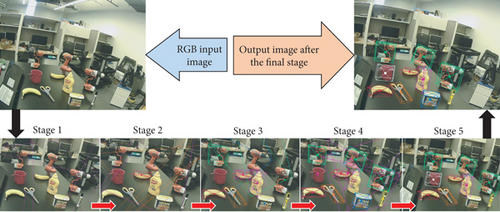
The early stages of generating 2D key points often produce ambiguities and unstable predictions that will be resolved by later stages. Figure 6 illustrates the process of generating 2D key points throughout multistages. Throughout the stages, the accuracy of predictions improves gradually. Poor performance of the first 3 stages is clearly indicated. However, the last 2 stages provide robust predictions where all target objects are well estimated by the final stage image.
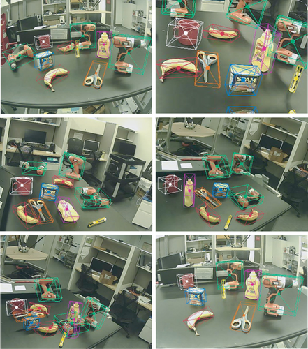
The pose estimation of target objects is further examined in difficult unstructured backgrounds. Figure 7 demonstrates the performance of pose estimation operating on seven target objects with multiple poses in unprepared lab environment and difficult backgrounds.
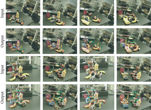
The perception network is able to estimate the object’s pose even when part of the object is invisible. Figure 8 shows instances of occlusions on different target objects. Object poses are well estimated even though objects obstruct each other randomly.
Another round of testing was necessarily carried out to show the network performance in various conditions of lighting. Figure 9 demonstrates the estimated poses of seven different objects in various illuminations. As seen in the figure, a light source was used closely to the target objects to disturb the image view and examine the perception capability in such lighting situations. The perception network performs robust and stable predictions of estimated poses of multitarget objects.

The ultimate tests of perception network have presented a sufficient model accuracy. That should be able to achieve 3D visual servoing in manipulation application. The next step is the implementation of a synthetically trained mobile manipulator system.
4.2. Visual Servoing for Long-Range Mobile Manipulator System
After examining the perception network, a complete autonomous system of 3D VS should be implemented to extract the performance characteristics. There is no need to conduct postrefinements of the estimated object’s pose. In addition, extra fine-tuning or retraining step is not required. Unlike a study in [32], our model detects and estimates the pose of target object with 3D bounding box regression. The estimated pose directly sends to the control scheme of the mobile manipulator system. The experiments of an entire AMM system were performed in simulation environment, as well as real-world settings.
In contrast to Bateux et al. in [33] who used gantry robot to execute 6DOF direct visual servoing task based on deep neural network method, our perception network does not rely on photometric details of an entire input image, in which image perturbations (such as pixel intensities) have no impact on VS performance. In addition, our robot model is applicable to both camera installations (eye-in-hand/eye-to-hand). This makes it more practical in a variety of scenarios.
4.2.1. Simulation Environment
Figure 10 demonstrates the experimental setup prepared in Gazebo (a 3D robotics simulator), a target object placed on the table is the desired pose of the robot end-effector. Frames of target object, camera, world base, and robot end-effector are processed by the robotics middleware ROS (Robot Operating System), all exhibited in 3D visualization tool called Rviz.
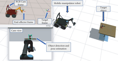
Multiple rounds of tests were carried out to show the performance of the entire system. A straight test is where the target object was placed in front of the robot. The end-effector of the robot moved as expected towards the detected target. Likewise, another test was performed but deliberately positioned target object at an angle to cause a curved trajectory for the end-effector.
4.2.2. Real-World Settings
Figure 11 shows the experimental setup carried out in the lab environment. Husky mobile base with 6DOF UR5 manipulator, mounted on the top of the mobile robot, was used with uncostly single camera placed at the end-effector. Tracking test was required to investigate the physical capabilities of the proposed AMM system.
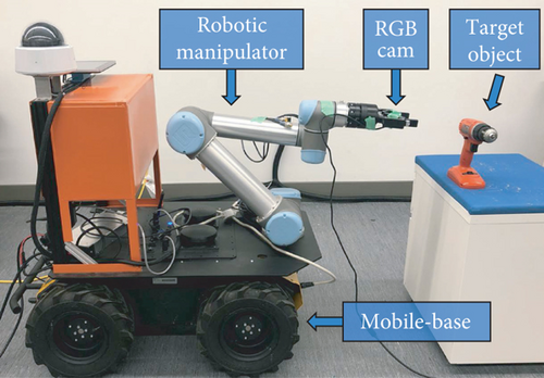
Figure 12 demonstrates a scene of the tracking test. Drill object was used as a target object. Figure 12(a) shows the frames of interest presented in Rviz visualizer, Figure 12(b) indicates the estimated pose of the target object, Figure 12(c) is the third person view that covers the used robot with the target object. Eye-in-hand camera installation was considered during the tracking test. This shows a stable and robust performance of the entire manipulation system.
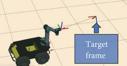
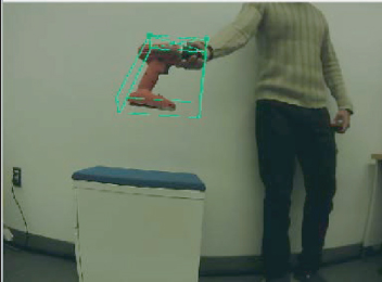
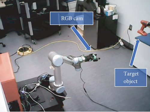
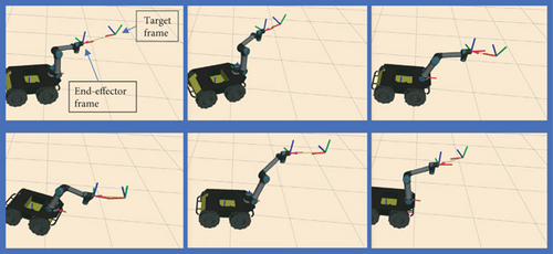
Figure 13 shows instances of the real-time tracking test, which occurs between the target object and end-effector of the AMM robot. Video recordings of the experiments have been provided to show the performance of the proposed AMM system. Comparing to such methods, our system estimates target competitively, which are trained only on synthetic data and generalized to physical 3D pose-based VS implemented in long-range mobile manipulator.
4.2.3. Robotic Manipulation
The ultimate purpose of this research is to develop an autonomous framework for vision-based mobile manipulation system. The accuracy of a perception network is adequate to execute continuous 3D VS implemented on long-range mobile manipulator. The goal of experiment is to perform an end-to-end real-time tracking test. Unlike the study in [17], our robotic model is not restricted to static objects and does not require objects to be placed in structured settings. In addition, the proposed system could successfully approach target object with 6DOF manipulation pose. This is different than traditional manipulation system in [34] which is only limited to top-down configuration. Moreover, our perception network entirely trains on computer-generated single images, and depth information or segmentation step is not required. This is unlike reference [6] which demands collections of synthetic and real-world dataset. Some recent studies might require manual data which gathered via human demonstration. It is worth mentioning that our robotic system is reliable to achieve tracking task with the 6DOF pose of dynamic object. This is appropriate to execute collaborative manipulation challenge (for instance handoff target object from the human to the robot).
To provide scalable visual manipulation system (unlike an approach in [35]), two different VS configurations (eye-in-hand and eye-to-hand) have been experimentally validated. Our robotic model can operate reliably even when the camera and target object are moving at the same time. This assists to overcome uncertainties of the environment and robotic kinematic model.
To demonstrate the proposed robotic system suitable for manipulation task, we carried out further experiments of the whole system. The robot was tasked to move to a desired pose relative to the target object. We ran 5 attempts per session for 5 different sessions. At each test, the starting pose of the end-effector was chosen differently. Similarly, target object was placed randomly within the workspace. The difference between the centroid of target object and end-effector frame was calculated as the average distance. This yields about 2-3 cm in any direction.
5. Conclusions
This work sets out to develop an autonomous 3D VS system based on DeepNet, implemented in a sophisticated mobile manipulator system, and utilized single RGB image. Two main steps construct the entire system: first, perception network to detect and estimate the pose of objects in 3D space, using an effective deep-ConvNet and pose estimation algorithms and model architecture. Second, the pose estimation data was then used in a 3D visual servoing scheme to control the motion of AMM system. Visual servoing control law was designed for the AMM model to avoid uncertain solutions of the inverse kinematics.
Perception network was entirely trained using computer-generated RGB images and depth images, and segmentations are not required. The system was, then, generalized successfully into real-world environment without fine-tuning or extra retraining. Besides simulation experiments, the proposed system was physically tested (on 6DOF manipulator arm mounted on differential robot base) to extract the performance characteristics of the robot model. The findings of experimentations have resulted in a robust and continuous 3D VS operations of AMM with handling occlusion and lighting variations. In terms of future work, it would be important to carry out further studies with the goal of applying object grasping.
Disclosure
The earlier version of the paper has been presented as a thesis form (https://ir.library.dc-uoit.ca/bitstream/10155/1311/1/Al_Shanoon_Abdulrahman.pdf).
Conflicts of Interest
The authors declare that they have no conflicts of interest.
Acknowledgments
This work was supported by the NSERC Discovery Program under Grant RGPIN-2017-05762 and the MITACS Accelerate Program under Grant IT14727.
Open Research
Data Availability
All data related to the paper will be available upon request through the corresponding author: Haoxiang Lang ([email protected]).


