Study on Numerical Simulation of Seismic Collapse of RC Frame Structure with Infilled Wall
Abstract
The infilled wall plays an important role in the formation of the survival space and life-saving passage of the seismic collapse of reinforcement concrete (RC) frame structure. Here, with the numerical modeling method of the infilled wall, the connection between infilled wall and RC frame was primarily investigated. The combined finite element (FE) and finite-discrete element (F-DE) method is proposed to simulate the multispan and multistory RC frame structure with infilled wall. The reliability of the numerical simulation method was verified by the shaking table test; the evaluation criterion includes the collapse mechanism and mode. The results show that the numerical simulation is highly consistent with the shaking table test; it is easy for RC frame structure to form short columns due to the influence of the low or half-height infilled wall, and the structural collapse is caused by the shear failure of columns; the overall structure shows pancake type of collapse; the survival space becomes smaller and smaller on the direction of structural collapse. The proposed numerical simulation method can be valuable in simulating RC frame structure with infilled wall for postearthquake rescue.
1. Introduction
The investigation results of the 2008 China Wenchuan M8.0 earthquake revealed that reinforced concrete (RC) frame structures are susceptible to collapse under a strong earthquake [1–3], for example, the pancake collapse of the Xuankou middle school building in Yingxiu town. The Lvbao hotel, environmental protection bureau (EPB), and meteorological bureau in Beichuan county collapsed in inclined type. RC frame structure's collapse types are various and distribution law of the survival spaces is blurred and indistinct, which makes it difficult for the postearthquake rescue work, as shown in Figures 1–4. The seismic damage investigation, shaking table test, and numerical simulation are currently utilized to investigate the seismic collapse of RC frame structure. The earthquake damage investigation can observe the building’s collapse type and survival space intuitively and truly, but the building ruins cannot be kept intact due to the use of the shoring, uplift, removal, and breach technology during the rescue, which can destroy the survival space in ruins. The shaking table test can simulate the seismic collapse process of the RC frame structure to some extent. Hang et al. [4], Zuo [5], and Luo et al. [6] carried out the shaking table test of multispan and multistory RC frame structure without infilled wall to investigate the seismic collapse mechanism of RC frame structure. Yang et al. (2015) [7] and Yue [8] carried out the shaking table test of multispan and multistory RC frame structure with infilled wall to investigate the seismic collapse law and distribution of survival space. However, the economy of shaking table test is high, particularly the full-scale test. Therefore, it is necessary to accurately simulate seismic collapse of RC frame structure by means of effective numerical simulations. Not only can the survival space be accurately analyzed, but also the life-saving channel can be constructed. The optimization and safety evaluation of life-saving channel can be realized, which will provide support for improving the rescue efficiency and safety of rescuers and trapped persons.
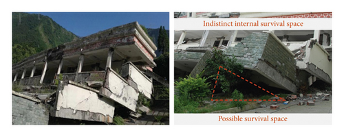
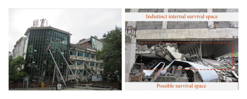
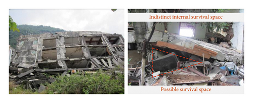
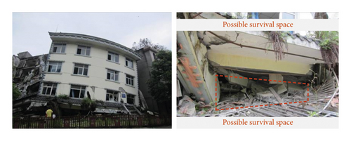
The numerical simulation of RC frame structure has been developed rapidly. Isobe Tsuda [9], Lu et al. [10, 11], and Lv et al. [12] established the numerical model of one-span and three-story, three-span × three-span and ten-story, and two-span × four-span and eight-story RC bare frame structure to finish the whole process of seismic collapse to analyze the collapse mechanism and mode of RC frame structure. However, the influence of infilled wall on the collapse of RC frame structure was not considered in the abovementioned research. Both the actual earthquake damage [13, 14] and shaking table tests [15–17] showed the infilled wall can change the stiffness, strength, and collapse mechanism of RC frame structure, particularly the collapse mode. Sattar and Liel [18] and Burton and Gregory [19] established one-span and one-story, one-span and three-story frame structure to investigate the influence of infilled wall on RC collapse mechanism, but the in-plane seismic performance of RC frame structure with infilled wall was only discussed. Both the actual seismic damage [20, 21] and shaking table tests [22–24] showed the out-plane failure of infilled wall is also a common earthquake damage, so infilled wall is subjected to the combined action of in-plane and out-plane seismic loading. However, the multispan and multistory RC frame structure with infilled wall is currently rarely studied. Sediek Omar et al. [25] established the numerical model of three-span × three-span and four-story RC frame structure with infilled wall to analyze the relationship between the collapse direction and ground motion intensity. This numerical mode adopts applied element method (AEM) [26] without considering the reinforced bar’s solid element instead of equivalent spring element; in addition, it is not easy to determine the failure criteria of spring element [27], which affects the final collapse mode of RC frame structure to a certain extent.
In summary, the existing studies take either multispan frame without infilled wall or one-span frame with infilled wall as research subject to investigate the seismic collapse mechanism of an RC frame structure. The main reason is that most scholars pay little attention to the collapse mode, including the survival space and life-saving passage, so the multispan and multistory RC frame structure with infilled wall is rarely studied. However, the distribution law of survival space and setting of life-saving passage are key problems during postearthquake rescue. Therefore, this paper attempts to give a reasonable numerical simulation method of the multispan and multistory RC frame structure with infilled wall according to the seismic damage characteristics of beam, column, and infilled wall and the relationship between infilled wall and RC frame. It provides support for accurately investigating the seismic collapse mechanism and mode, the distribution law of survive space, and optimizing the life-saving passage of RC frame structure.
Subsequently, the key technologies of numerical simulation method of RC frame structure with infilled wall are discussed in Section 2. The numerical model and shaking table test of RC frame structure with infilled wall will be carried out in Section 3. The collapse mechanical response and mode of numerical simulation and shaking table test are compared in Section 4. The collapse mechanism and distribution law of survival space of RC frame structure are analyzed in Section 5.
2. Modeling Method
2.1. Modeling Method of Beam, Slab, and Column
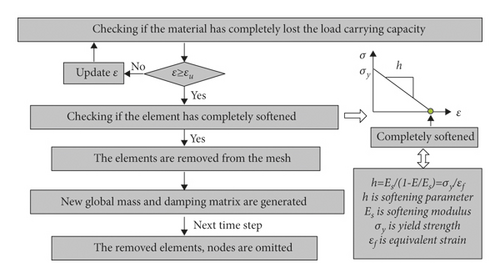
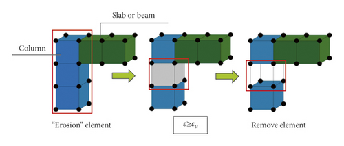
The actual seismic damage [28], shaking table tests [29, 30], and numerical simulations show that the story failure mode of RC frame structure is one of the main reasons for the overall collapse of buildings due to the column hinge mechanism. The failure phenomenon is that the plastic hinge appears at the column end, and the bottom column is inclined, with the overall structure collapse. Figure 5 shows the final collapse state of the Xuankou middle school building; the seismic damage phenomenon includes column hinge, spalling concrete, and exposed reinforcement. For the abovementioned reasons, the element deletion (erosion) technique (EDT or EET) in finite element method (FEM) can be utilized to simulate RC frame beam, slab, and column. The principle of EDT is that the finite element will be removed from the mesh as soon as the strength vanishes at the end of strain softening process. A single time step of the algorithm is often divided into a series of phases (Figure 6). Figure 7 is the schematic diagram of column (beam) element deletion. However, the disadvantages of the EDT include high dependence on the mesh and nonconservation of mass and momentum in the deleted region, particularly in large-scale element models (Alsos) [31]; hence the finite element size should not be too large. EDT is utilized by many researchers to simulate the collapse of RC frame structures because it is applied in many finite element programs, such as LS-Dyna, Abaqus, and MSC.Marc, etc. Lu et al. [32] proposed a fiber-beam element model and multilayer shell model and utilized EDT in MSC.Marc software to simulate the collapse process of a ten-story RC frame structure. Elsanadedy et al. [33] and Qian et al. [34] analyzed the collapse of single-story and multistory RC frame structures by using EDT in LS-Dyna software, respectively.

2.2. Modeling Method of Infilled Wall
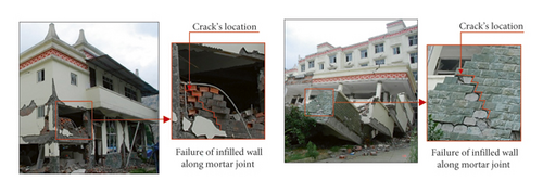
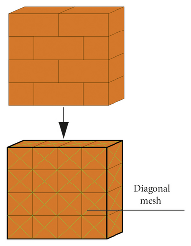
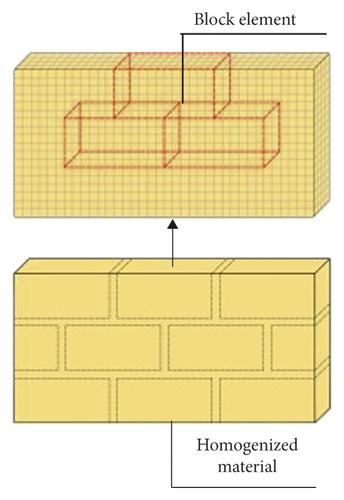
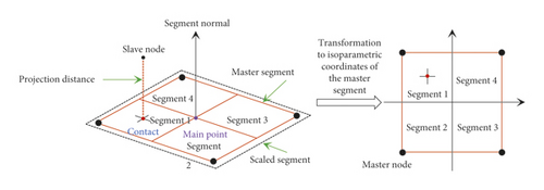
The investigation results of the Wenchuan M8.0 earthquake revealed that the strength of the mortar interface between infilled wall blocks is low, and cracks and failures occur on the contact surface of blocks [35, 36], as shown in Figure 8. For abovementioned reason, finite-discrete element method (F-DEM) can be utilized to simulate infilled wall of RC frame structure. Finite-discrete element method (F-DEM) is a novel computational approach developed by Munjiza et al. [37–40] and is a special branch of the DEM family. The structures are discretized using discrete elements in this approach, with a finite element mesh integrated into each discrete element. The process of fracture and breakage is observed in the finite element mesh, and each discrete element is deformable. F-DEM is widely utilized to predict the entire failure process of masonry structure from continuity to discontinuity. Smoljanovic et al. [41], Munjiza et al. [42], and Chen et al. [43] simulated the process behavior of masonry structure from the initial state to the final collapse by F-DEM. Actually, infilled wall cracks can also appear on blocks themselves; thus, the infilled wall can be meshed diagonally and the contact is considered, as shown in Figure 9. In addition, infilled wall is simplified as the homogeneous material when the strength of mortar is consistent with block, as shown in Figure 10.
2.3. Modeling Method of the Connection between Infilled Wall and Frame
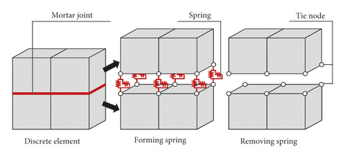
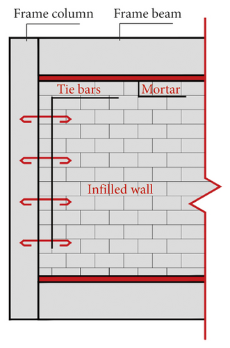
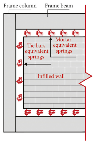
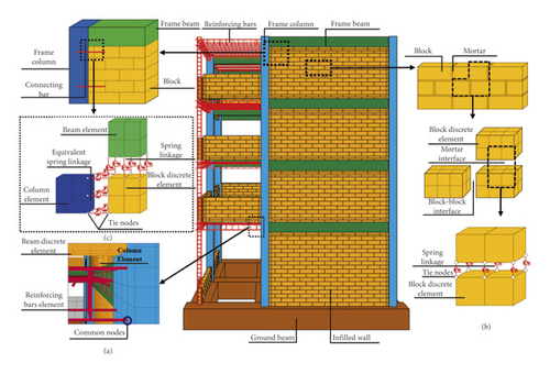
Figure 14(a) is structural drawing between infilled wall and RC frame; the tie bars were set between infilled wall and RC frame column to ensure the in-plane and out-plane seismic performance of infilled wall according to the code for seismic design of building in China [52], and the infilled wall and RC frame beam is filled with mortar. Figure 14(b) is equivalent drawing between infilled wall and RC frame; the tie bars and mortar are simplified as springs with normal force and shear force. Tie-break contacts (in NRA) were set on the contact surface between infilled wall and frame column and beam to realize the simplified spring. In order to realize the combination of infilled wall and RC frame, the frame column and beam element mesh adopted a common node, node1 and node2 were merged together, and similarly, node3 and node4 were also merged together. The same coordinate nodes of infilled wall elements were not merged. Instead, springs were set between nodes. The tie bar between the frame column and the infilled wall was equivalent to the springs, which were set between node 3, node 5, and node 6, as shown in Figure 15.

In summary, according to the actual seismic damage characteristics, structural construction measures, and structural design code of RC frame structure in China, the combined FEM and F-DEM are proposed to simulate the seismic collapse of the multispan and multistory RC frame structure with infilled wall. The actual seismic damage building is taken as the numerical simulation and experimental model, and the accuracy of the simulation method is validated by the shaking table test.
3. Numerical Model and Shaking Table Test Model
3.1. Model Structure
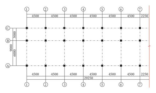
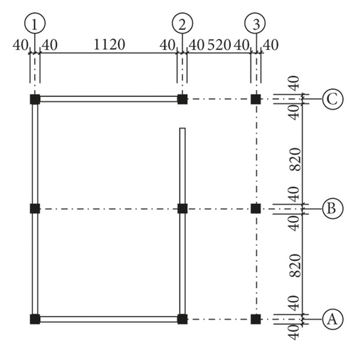
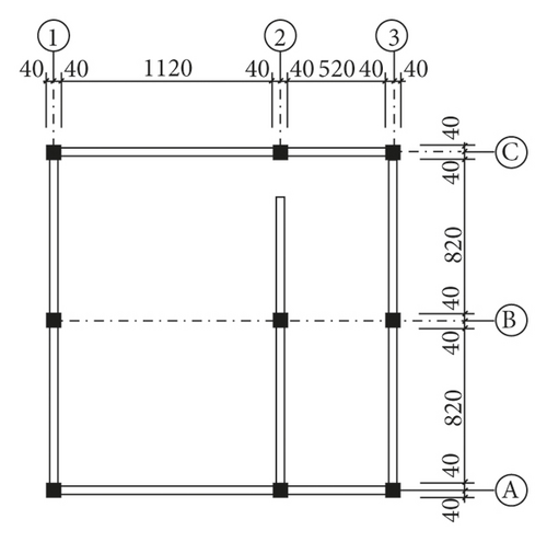
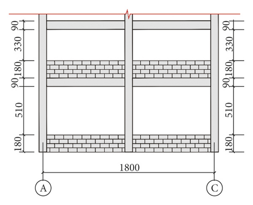
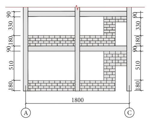
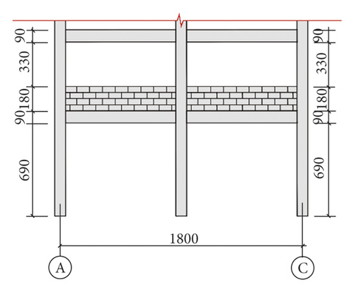
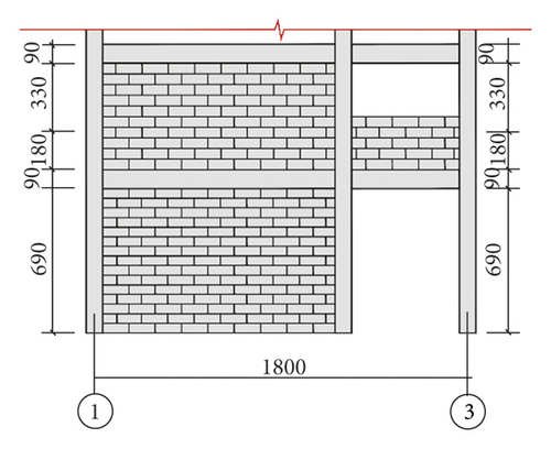
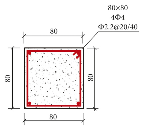
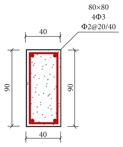
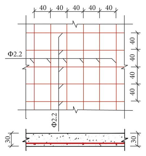
The Xuankou middle school building is one of the most typical collapsed RC frame structures in the 2008 China Wenchuan M8.0 earthquake; its column grid layout is shown in Figure 16. This paper selects two-span × two-span and four-story from the Xuankou middle school building; the numerical model and shaking table test model were established at the scale of 1/5. The strength grade of concrete, reinforcement, block, and mortar are C10, Q235, Mu3.5, and Mb5, respectively. The architectural drawing (2nd, 3rd, and 4th floor plan and elevation are the same) and structural reinforcement drawing are shown in Figures 17 and 18.
3.2. Numerical Model
3.2.1. Numerical Model Scheme
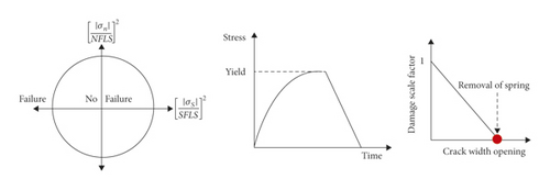
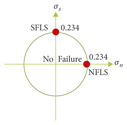
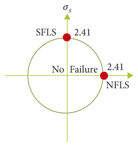
Figure 19 shows the detailed modeling scheme of RC frame structure with infilled wall. Figure 19(a) shows the modeling scheme of the beam, slab, and column of the RC frame, which adopts the separate common node method. The bond-slip effect between reinforcement and concrete is not considered to improve the overall model’s calculation efficiency. Concrete is simulated using 8-node solid elements with reduced integration. To eliminate the hourglass problem, hourglass control type 5 and hourglass coefficient of 0.05 were used. Reinforcing bars were modeled using 2-node Hughes-Liu beam elements with 2 × 2 Gauss quadrature integration at the cross section. This beam formulation can simulate the behavior of axial force, biaxial bending, and finite transverse shear strains (Hallquist) [53]. Figure 19(b) depicts the modeling scheme of infilled wall, which adopts NRA. According to the code for the design of masonry structures in China [54], the mortar shear failure stress SFLS = k5 = 0.234 × 10⁶ pa, where k5 is 0.125, f2 is the average compressive strength of mortar (3.49 × 10⁶ pa from test), and the tensile strength can be approximately regarded as equal to the shear strength, and the mortar normal failure stress NFLS = 0.234 × 10⁶ pa, as shown in Figure 20. Brameshuber and Schmidt [55] investigated the mechanical properties of mortar via test, using a sliding friction coefficient of 0.7. Figure 19(c) shows the modeling scheme of the connection between infilled wall and RC frame. The failure limit of equivalent normal stress NFLS = N × σy/n = 2.41 × 10⁶ Pa, where N is the number of tie bars (160), σy is the tensile strength of the tie bar (1.15 × 10⁸ Pa from test), and n is the number of normal springs (7630). Similarly, according to the code for design of concrete structures in China [56], the shear strength of reinforced bar can be approximately regarded as equal to the tensile strength; thus the failure limit of equivalent shear stress SFLS is 2.41 × 10⁶ Pa, as shown in Figure 21. The sliding friction coefficient between infilled wall and beam is 0.7.
3.2.2. Numerical Model Material
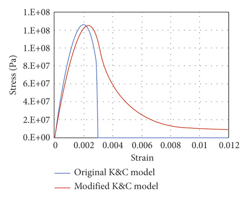
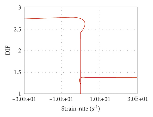
It is vital to accurately define the failure criteria of concrete materials to achieve seismic collapse of the RC frame structure and avoid unreasonable element deletion. If the ultimate tensile strain and compressive strain in the code for design of concrete structures [56] are utilized as the concrete failure criteria, the capacity of concrete cracking and closing to continue compression will be ignored, and the structure’s story drift capacity will be underestimated. Thus, from the calculation results without failure criterion, the strain at the expected failure moment of the element is 0.021 and is regarded as the failure criterion of concrete material. The failure of concrete material is realized by adding Mat_add_Erosion in LS-DYNA software.
The Cowper-Symonds model (Mat_003 in LS-DYNA R10.0) [62] (Jones, 1983) is utilized to simulate reinforcement bars material. This model is suited to model isotropic and kinematic hardening plasticity as well as rate effects. The main parameters of the model include young’s modulus, yield stress, tangent modulus, ultimate strain, and strain rate. Lin et al. [63] referring to the mechanical property test of reinforcement bars chose 0.015 as the ultimate tensile strain of HPB235.
The Winfrith-Concrete model (Mat_084 in LS-DYNA R10.0) (Broadhouse) [64] is utilized to simulate the infilled wall material. This model is a smeared crack (sometimes known as pseudocrack), smeared rebar model, implemented in the 8-node single integration point continuum element. The advantage of this material model over other models is that it allows for a graphical representation of the cracks within the finite element in postprocessors of LS-DYNA. The model’s main parameters include density, young’s modulus, uniaxial compressive strength, uniaxial tensile strength, fracture energy, or crack width.
Modified K&C model parameters, Cowper-Symonds model parameters, and Winfrith-Concrete model parameters are mentioned in Tables 1–3.
| Density ρ | Compressive strength fc | Tensile strength ft | Damage parameter b1 | Damage parameter b2 |
|---|---|---|---|---|
| 6.9 E + 02 kg/m3 | 1.25 E + 07 Pa | 1.2 + 06 Pa | 1.6 | 2 |
| Damage parameter b3 | Peak damage λm | a | ac | ad |
| 1.15 | 5.6 E − 05 | 3 | 0.294 | 1.86 |
| Density ρ | Young’s modulus E | Yield strength σy | Tangent modulus Et | Ultimate strain |
|---|---|---|---|---|
| 2.27 E + 05 kg/m3 | 1.2 E + 11 Pa | 1.15 E + 08 Pa | 1.2 E + 10 Pa | 0.015 |
| Density ρ | Young’s Modulus E | Uniaxial compressive strength fc | Uniaxial tensile strength ft | Crack width |
|---|---|---|---|---|
| 5.39 E + 04 kg/m3 | 6.12 E + 09 Pa | 3.58 E + 06 Pa | 3.58 E + 05 Pa | 0.0024 m |
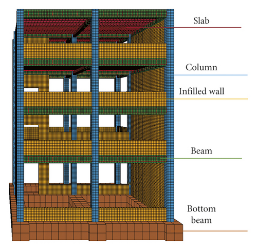
The element mesh size should not be too large because the RC frame adopts the element deletion technique in FEM. However, the mesh size should not be too small because the calculation time is inversely proportional to the time step in LS-DYNA; the time step is proportional to the element characteristic length according to the Courant Friedrichs Lewy criterion [65]. Therefore, the element size of beams, columns, and infilled walls is 20 mm, the element size of slabs is 40 mm, and the element of the foundation beam is 100 mm. The number of elements is 140489. The numerical model of RC frame structure is shown in Figure 24.
3.3. Shaking Table Test Model
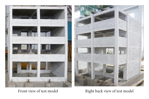
According to 3.1, the shaking table test model is the same as the numerical model, and the scale is 1/5. The shaking table test model takes the length, concrete elastic modulus, and acceleration similarity ratio as the basic quantities, and the test similarity ratio is deduced according to the similarity criterion (Table 4). The beam, slab, and column of test model are cast by C10 microconcrete and Q235 iron wire, and the infilled wall is poured by MU3.5 concrete hollow block and Mb5 composite mortars. The test model needs 5.73 tons’ additional weight, which is distributed to each floor. The additional weight of the top floor is 1.23 tons, and the additional weight of other floors is 1.5 tons. The shaking table test model is established at the scale of 1/5; the test model materials are obtained according to the test similarity ratio in Table 4. Table 5 shows the materials of full-scale structure and 1/5 scale model. The front view and right view of shaking table test model of RC frame structure are shown as Figure 25.
| Physical quantity | Similarity relation | Similarity ratio |
|---|---|---|
| Length | lr | 0.20 |
| Elastic modulus | Er | 0.583 |
| Acceleration | ar | 1.00 |
| Stress | σr = Er | 0.583 |
| Time | 0.447 | |
| Frequency | 2.236 | |
| Displacement | lr | 0.2 |
| Velocity | 0.447 | |
| Equivalent density | 2.915 | |
| Mass | 0.0233 |
| Type | Full-scale structure | 1/5 scale model | |||
|---|---|---|---|---|---|
| C30 | HRB335 | HPB300 | C10 | HPB235 | |
| Elastic modulus (GPa) | 30 | 200 | 210 | 17.5 | 210 |
| Compressive (yield) strength (MPa) | 30 | 335 | 300 | 10.3 | 235 |
3.4. Sensor Arrangement and Loading Scheme
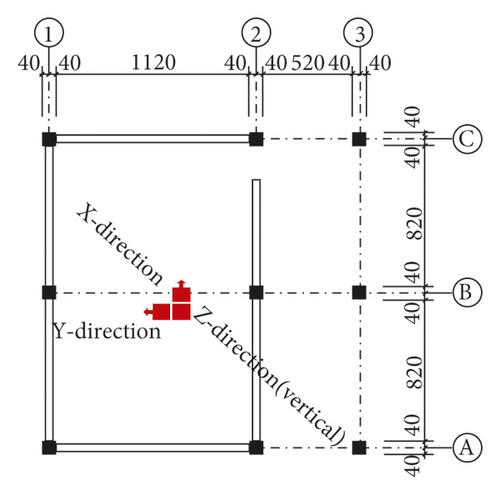
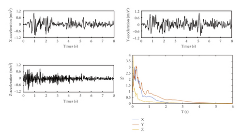
As shown in Figure 26, three (2 horizontal and 1 vertical) displacement sensors and three (2 horizontal and 1 vertical) acceleration sensors are installed on each floor of the test model; in addition, three acceleration sensors and three displacement sensors are installed on the shaking table. A classical earthquake acceleration record of site II was selected, which is the EI-Centro wave of the 1940 Valley earthquake (normalization). The earthquake wave needs to be processed because the test model is scaled. The acceleration similarity ratio is 1 and time similarity ratio is 0.447. Therefore, time was compressed to obtain the acceleration time history, as shown in Figure 27; the load case inputs are provided in Table 6. Firstly, the scan frequency test of the shaking table test model was carried out with white noise in order to obtain the natural period of the test model; then 3-direction (3D) ground motion was input, according to the code for seismic design of building in China [51]; PGA ratio of X, Y, Z is 1 : 0.85 : 0.65.
| No. | Ground motion | PGA (g) | Remarks |
|---|---|---|---|
| 1 | White noise | 0.02 | 3D |
| 2 | El-Centro | 0.06 | 3D shaking, intensity 7 medium eq. |
| 3 | El-Centro | 0.25 | 3D shaking, intensity 7 rare eq. |
| 4 | El-Centro | 0.39 | 3D shaking, intensity 8 rare eq., collapse |
4. Model Validation
4.1. Comparison of Natural Period between the Test and Numerical Simulation
The natural period of the test and numerical model was compared to verify the accuracy of the numerical model. The natural period of the test model was obtained by the scan frequency test and the natural period of the numerical model was obtained by the structural dynamic property analysis, as shown in Table 7. The difference value of the natural period was 0.013 s and 0.021 s in X direction and Y direction, which shows that the numerical model has a certain reliability.
| Type | Test model (s) | Numerical model (s) | Difference value (s) |
|---|---|---|---|
| The natural period (X direction) | 0.158 | 0.171 | 0.013 |
| The natural period (Y direction) | 0.122 | 0.143 | 0.021 |
4.2. Comparison of Collapse Mode between the Test and Numerical Simulation
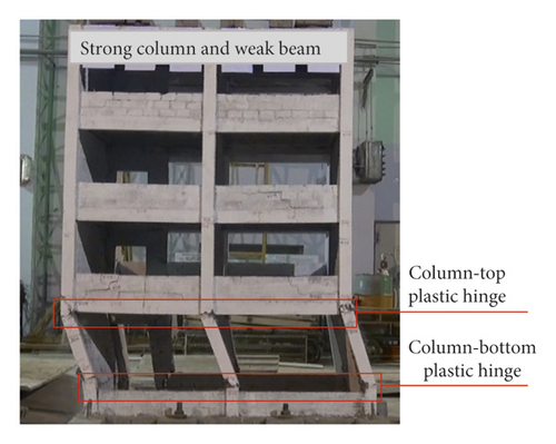
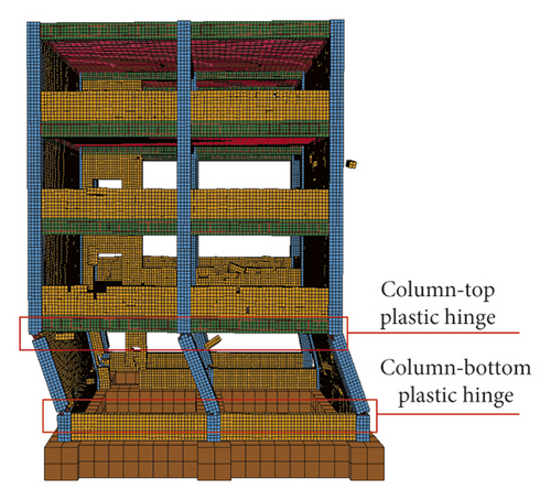
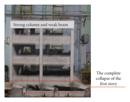
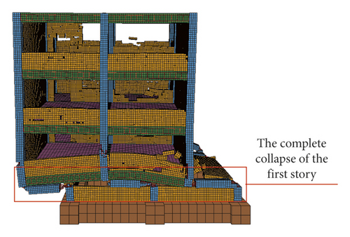
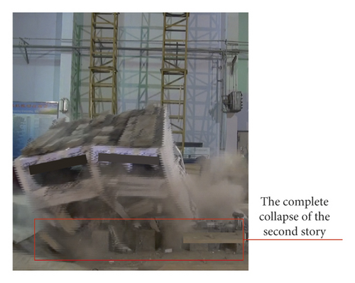
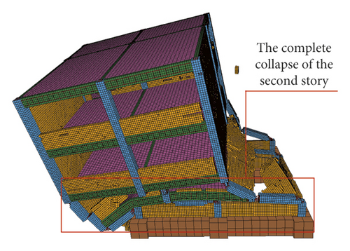
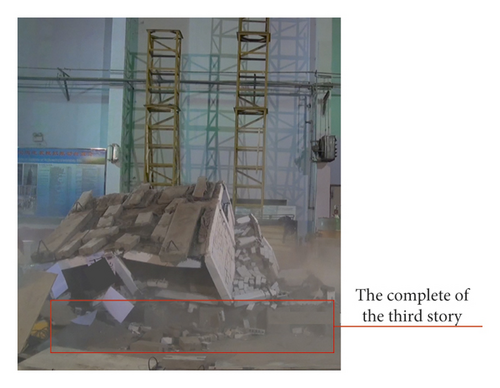
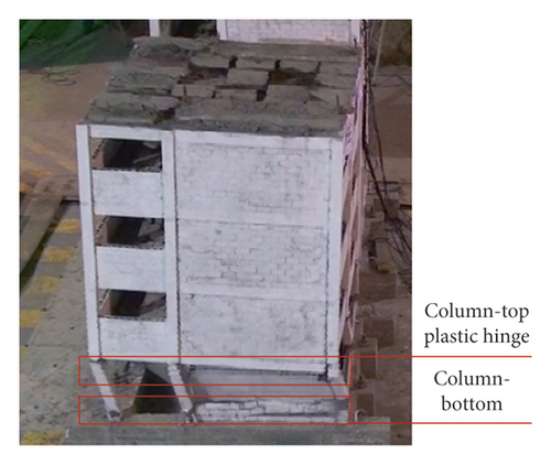
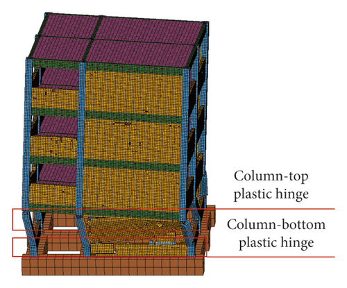
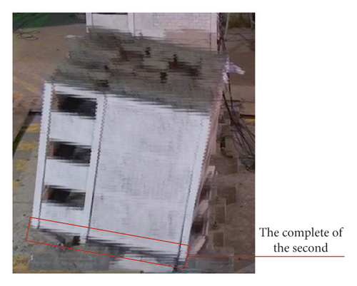
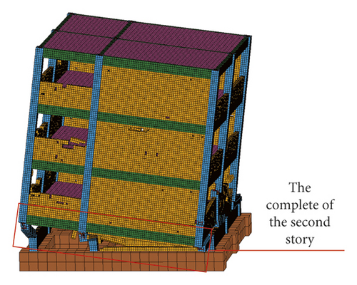
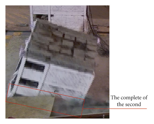
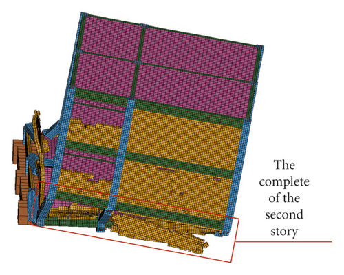
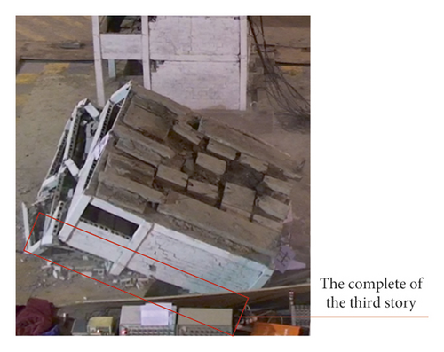
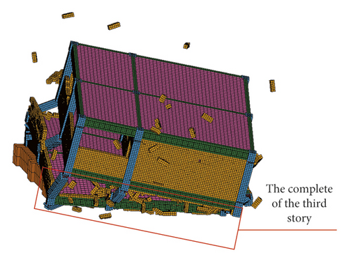
The four main failure stages of the numerical simulation and shaking table test of RC frame structure were compared (Figures 28–43). In the first stage, the first-story columns of the numerical model and test model were inclined, and plastic hinges appear at the top and bottom of columns, which leads to structural instability {Figures 28, 29, 36, and 37}. In the second stage, the first story of the numerical model and test model collapsed completely; however, the deformation of the upper structure was not obvious and the vertical member did not lose stability {Figures 30, 31, 38, and 39}. In the third stage, the second story of the numerical model and test model collapsed completely; the upper structure was inclined to the front right direction {Figures 32, 33, 40, and 41}. In the fourth stage, the third story of the numerical model and test model collapsed completely; however, the fourth story was intact {Figures 34, 35, 42, and 43}.

4.3. Comparison of Structural Response between the Test and Numerical Simulation
The story drift and acceleration time-history response of the numerical simulation and shaking table of RC frame structure were compared. The story drift was taken as the envelope value of maximum relative displacement during El-Centro earthquake with PGA of 0.06 g, 0.26 g, and 0.39 g (Figure 44). The acceleration time-history response of first and fourth story of RC frame structure is obtained during EI-Centro earthquake with PGA of 0.39 g (Figure 45).
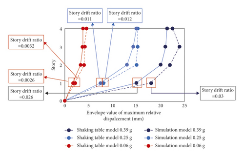
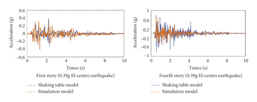
As shown in Figures 27–42, the collapse mode and type of the numerical simulation correlate well with the shaking table test result in the four main failure stages. As shown in Figure 43, the story drift ratio of the shaking table test and numerical simulation were 0.0026 and 0.0036, 0.011 and 0.012, 0.026 and 0.03 under the action of earthquake with PGA of 0.06 g, 0.25 g, and 0.39 g, and the difference of story drift ratio was about 0.002, which is relatively small. The maximum story drift ratio of 0.026 and 0.03 can be used as the near-collapse story drift ratio of RC frame structure, which can provide reference for standard design for anticollapse RC frame structure. Meanwhile, the maximum story drift ratio appeared in the first story, which can be classified as the collapse vulnerable story of RC frame structure. As shown in Figure 44, the variety laws of acceleration response of the shaking table test and numerical simulation are similar, and the main acceleration peak is similar.
In summary, it shows that the combined FEM and F-DEM can accurately simulate the seismic collapse of the multispan and multistory RC frame structure with infilled wall.
5. Collapse Mechanism and Survival Space
5.1. Collapse Mechanism
As shown in Figures 28–31, the greater the load resistance ratio of the column, the easier it is to break first and collapse toward the longer-span direction with torsion. The characteristics of the collapsed RC frame structures are broken-bone-with-connected-tendons and pancake type, as shown in Figures 46 and 47.
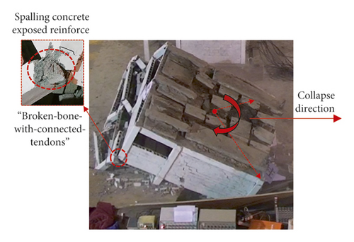
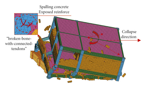
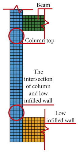
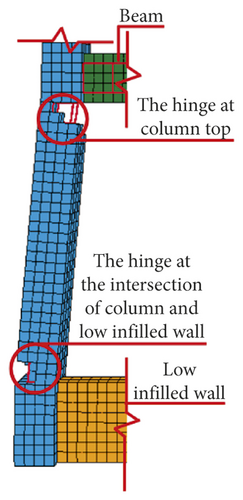
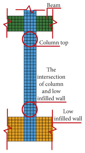
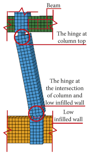
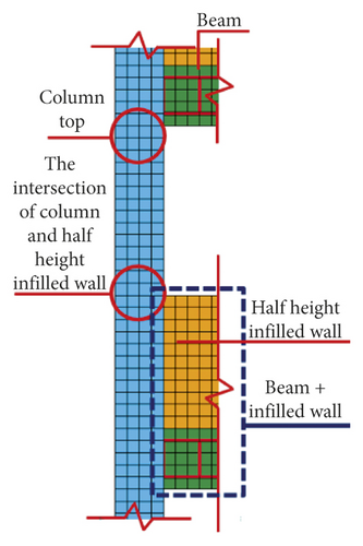
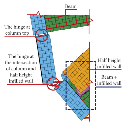
The shear failure of the frame column was the main reason for the collapse of RC frame structure and it was due to the influence of low or half-height infilled wall. The RC frame structure shows the failure mechanism of “strong beam and weak column.” The main reason was that “frame beam + upper half-height infilled wall” increases the actual stiffness of the frame beam and shortens the height of frame column, which forms the short column. The plastic hinges appeared at column top or the intersection of column and half-height infilled wall, and the frame column is shear failure, as shown in Figures 48–53.
5.2. Survival Space
People tend to take refuge when strong earthquake event occurs. The survived people often hide in some small spaces in the ruins, which are called survival space. It is necessary for rescuers to determine the distribution of survival spaces quickly to construct the life-saving passage safely, which can improve the rescue efficiently and reduce casualties. The distribution of survival space is determined through the method of the shaking table test and numerical simulation; however, it is difficult to observe the small survival spaces inside the collapsed ruins through the shaking table test. Therefore, the distribution of survival spaces of RC frame structure’s ruins was briefly analyzed by numerical simulation.
- (1)
The damage of RC frame structure is often concentrated at the lower floors, which implies that the more upward, the lighter the damage. Evidentially, the top floor’s column did not form plastic hinge and still maintained stability. The distribution of survival spaces: From the ground floor to the top floor, the lighter the damage, the bigger the survival space (Figure 54).
- (2)
The columns with longer-span easily lose stability or vertical supporting capacity due to the different axial compressive ratio of columns, and the structure easily collapsed toward longer-span. The column with smaller-span was often damaged slightly and still had supporting capacity. The distribution of survival spaces: the survival spaces become smaller and smaller toward the direction of structural collapse (Figure 55).
- (3)
On the collapsed side, there may be some triangular survival spaces under the frame beam due to the support of the beam to the upper slab. The size of the survival space was related to the beam height and the inclination angle of beam (Figure 56).
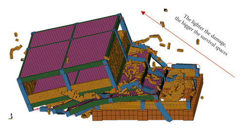
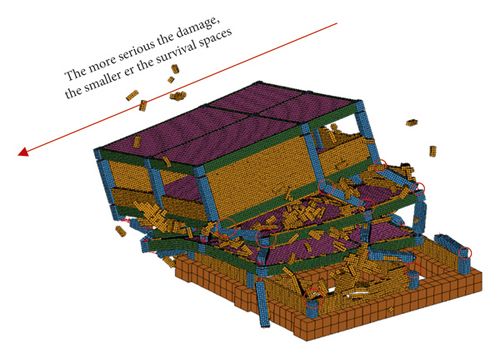
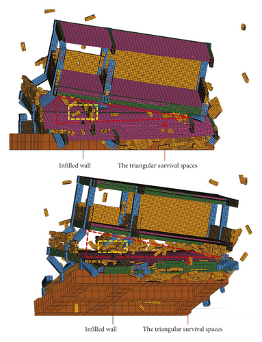
As shown in Figure 46, there are infilled walls in the survival spaces of the collapsed ruins, and the infilled walls play a very crucial role in the formation of the survival spaces. It can be seen that the infilled wall cannot be ignored to simulate the RC frame structure’s collapse mode, particularly the survival spaces, and it can also provide a basis to study the life-saving passage accurately.
6. Conclusions
- (1)
The numerical simulation correlates well with the shaking table test result and will provide the precondition to accurately simulate the seismic collapse of the multispan and multistory RC frame structure with infilled wall to analyze the distribution of survival space of collapsed RC frame structure and construct the numerical model of life-saving passage in ruins.
- (2)
The element deletion technology in FEM was utilized to simulate the beam, slab, and column of the RC frame. It can be realized that the spalling of beam and column concrete and the collapse mechanism of the structure were consistent with the seismic damage phenomenon of the main structural components of the RC frame structure.
- (3)
The nodal release approach (NRA) in F-DEM was adopted to simulate infilled wall and the relationship between infilled wall and the RC frame. It simulated the entire structure from the initial state to the collapse state of the infilled wall and also considered the connecting bar between infilled wall and RC column as well as avoiding the excessive disappearance of infilled wall elements.
- (4)
The numerical simulation and shaking table test showed the seismic collapse of the RC frame structure toward long-span direction with torsion, with the formation of the characteristics of the collapsed structures being broken-bone-with-connected-tendons and pancake type. The shear failure of the frame column is the main reason for the collapse of RC frame structure due to the influence of low or half-height infilled wall.
- (5)
The story drift ratio of 0.026 and 0.03 can be utilized as the near-collapse story drift ratio of RC frame structure, which can provide reference for standard design for anticollapse RC frame structure. The RC frame structure collapsed completely due to the vulnerable story at the first floors; thus, it is suggested to improve the seismic performance of the first floor; the soft connection between frame column and low infilled wall is recommended to avoid short column damage.
- (6)
The distribution of survival spaces: The higher the floor, the bigger the survival space; and the survival spaces on the collapsed side are small, and hence there may be some triangular survival spaces under the frame beam.
- (7)
The infilled wall plays a very crucial role in the formation of the survival spaces of RC frame structure’s collapsed ruins; therefore the infilled wall cannot be ignored in simulating the survival space and life-saving passage of the seismic collapse of RC frame structure. The proposed numerical simulation method can be valuable in simulating RC frame structure with infilled wall for postearthquake rescue.
Conflicts of Interest
The authors declare no conflicts of interest. The funders had no role in the design of the study; in the collection, analyses, or interpretation of data; in the writing of the manuscript; or in the decision to publish the results.
Authors’ Contributions
Conceptualization was done by J. D. and D. X.; methodology was developed by D. X. and Q. Y.; software was provided by D. X; validation was done by D. X., J. D., and Q. Y.; formal analysis was done by D. X.; investigation was done by D. X. and X. W.; data curation was done by D. X., G. S., and X. W.; original draft was written by D. X.; reviewing and editing were done by D. X., J. D., Q. Y. X. W., and G. S.; project administration was done by J. D. and Q. Y. All authors have read and agreed to the published version of the manuscript.
Acknowledgments
Thanks are due to the Key Laboratory of Earthquake Engineering and Engineering Vibration of China Earthquake Administration for convenient conditions to complete the shaking table test. This research was funded by the National Key Research and Development Program of China (no. 2018YFC1504400) with title of “Search & Rescue Techniques for Mass Casualties in Urban and Metropolis Area Impacted by Catastrophic Earthquake.”
Open Research
Data Availability
The data used to support the findings of this study are included within the article.


