A Modified Algorithm Based on Haar Wavelets for the Numerical Simulation of Interface Models
Abstract
In this paper, a new numerical technique is proposed for the simulations of advection-diffusion-reaction type elliptic and parabolic interface models. The proposed technique comprises of the Haar wavelet collocation method and the finite difference method. In this technique, the spatial derivative is approximated by truncated Haar wavelet series, while for temporal derivative, the finite difference formula is used. The diffusion coefficients, advection coefficients, and reaction coefficients are considered discontinuously across the fixed interface. The newly established numerical technique is applied to both linear and nonlinear benchmark interface models. In the case of linear interface models, Gauss elimination method is used, whereas for nonlinear interface models, the nonlinearity is removed by using the quasi-Newton linearization technique. The L∞ errors are calculated for different number of collocation points. The obtained numerical results are compared with the immersed interface method. The stability and convergence of the method are also discussed. On the whole, the numerical results show more efficiency, better accuracy, and simpler applicability of the newly developed numerical technique compared to the existing methods in literature.
1. Introduction
Interface models play an important role in many disciplines including electromagnetic wave propagation, material science, fluid dynamics, and biological systems. The shared boundary between the two intervals in case of one-dimensional domains or between two regions in case of higher-dimensional domains is known as an interface. These domains (intervals or regions) are kept together with the help of suitable jump constraints. These phenomena can be modeled by using partial differential equations (PDEs) or ordinary differential equations (ODEs), where the parameters in these differential equations across the interface separating the two materials or states are discontinuous. Interface model is a mathematical model which considers two identical or different materials at different states having a shared boundary. The example of interface models with same materials in different states is water and ice, while water and oil is an example of interface models with different materials [1, 2]. These models frequently arise in heat conduction, Navier-Stokes flows, crystal growth, wave propagation through nonhomogeneous media, and models of solidification. Most of the interface model equations consist of highly varying coefficients [1, 3, 4]. The approximations of various physical and biomedical models often consist of highly varying coefficients or heterogeneous ODE or PDE models [5].
The solution of these models is a challenge for many standard numerical methods such as finite element method, finite volume method, and finite difference method. These methods have either poor performance or unable to catch the discontinuity in the solution. Due to the numerous applications of such type of models, several numerical methods have been introduced for the solution of these models with regular and irregular geometries in literature. Some of the numerical methods are immersed boundary method (IBM) [6, 7], immersed interface method (IIM) [1, 8], ghost fluid method (GFM) [9], matched interface and boundary method (MIBM) [10–12], the method based on the integral equations approach [13], and finite element methods [14–17].
Recently, wavelet analysis has got much popularity in the approximation theory. Different wavelets and approximating functions are introduced for approximation purpose. Wavelets have simple and fast algorithms, which result better approximation. Among all these wavelets, Haar wavelet has got great importance due to their simplicity and applications. Haar wavelet contains piecewise constant box functions. The Haar wavelet collocation method (HWCM) got attention of many authors due their simple nature, properties of orthogonality, and compact support. The Haar wavelet contains piecewise constant functions; therefore, complicated models can be approximated very easily using these wavelets. Besides, several types of boundary conditions including local and nonlocal conditions can be utilized. Various applications of HWCM in the approximation theory can be seen in [18–27]. Some of the recent work using Haar wavelets is given in [28–36].
In this article, a new approach based on Haar wavelet and finite difference method is developed for the numerical solution of advection-diffusion-reaction type elliptic and parabolic interface models.
The article is organized as follow. In Section 3, definition of the Haar wavelet and their integrals are presented. In Section 4, construction of the newly proposed numerical method based on Haar wavelet and FDM is given. The convergence and stability analysis of the proposed numerical method are discussed in Sections 5 and 6. In Section 7, numerical validation of the method is given. In the last section, conclusion is presented.
2. Governing Models
2.1. Elliptic Interface Model
2.2. Parabolic Interface Model
The functions f1(η), α1(η) > 0, β1(η) > 0, and σ1(η) ≥ 0 and f2(η), α2(η) > 0, β2(η) > 0, and σ2(η) ≥ 0 are smooth functions defined on I1 and I2, respectively.
3. Haar Wavelets
4. Numerical Procedure
In this section, formulation of numerical technique both for elliptic and parabolic advection-diffusion-reaction type interface models is discussed. The interval of study is considered to be [a, b] = [0, 1].
4.1. HWCM for Elliptic Model with Single Interface
The remaining procedure will be explained separately for both linear and nonlinear cases.
4.1.1. Linear Case
Equation (34) can be solved by any linear solver in order to get the unknown Haar coefficients. Now utilizing these unknown Haar coefficients in Equations (23) and (26), we can easily obtain the approximate solution of the problem.
4.1.2. Nonlinear Case
Equations (41) and (42) along with Equations (27) and (28) give a linear system of size with the unknown Haar coefficients and the values v1η(ζ) and v2η(ζ). The above linear system can be solved by using any linear solver.
4.2. HWCM for Parabolic Model with Single Interface
The remaining procedure is explained for linear and nonlinear cases separately in the upcoming section.
4.2.1. Linear Case
Solving system (61) by any linear solver, we obtained the values of the unknown Haar coefficients , , v1η(ζ, t), and v2η(ζ, t). By utilizing these unknown Haar coefficients in Equations (46) and (49), we can easily obtain the approximate solution of the problem.
4.2.2. Nonlinear Case
Equations (63) and (64) together with Equations (50) and (51) give a linear system of size . Solving the system by any linear solver, we can get the unknown Haar coefficients. Using these unknown Haar coefficients, we can easily obtain the approximate solution.
5. Convergence
Lemma 1 [39]. Assume that v ∈ C2(−∞, ∞) with |v′| ≤ K, ∀η ∈ (a, b), K > 0, and , and then, |λi| ≤ K2−(3j − 2)/2.
Lemma 2 [39]. Let v ∈ C2(−∞, ∞) be continuous on (a, b). Then, the error norm at Jth level satisfies
Theorem 3. If v(η) is the exact solution and is the approximate solution of Equation (1), the error norm at Jth level resolution is given by
Proof. The error estimate of the proposed method at Jth level resolution is given as
Now, using Lemmas 1 and 2, inequality (69) can be written as
Theorem 4. If v(η, tp) is the exact solution and is the approximate solution of Equation (7) and if p = 0, 1, 2 ⋯ P, where P is a positive integer, then the error norm at J-th level resolution is given by
6. Stability

Here, δt is the time step which is always positive, i.e., δt > 0. We have discussed the following three different cases related to Equation (82).
Case 1. If λ = 0, then Equation (82) gives
Case 2. If λ < 0, i.e., λ = −ξ2, where ξ ∈ ℝ, then Equation (82) gives
Case 3. If λ > 0, i.e., λ = ξ2, then Equation (82) gives
Thus, Equation (82) is valid for Cases 1 and 2, which are verified computationally in Figure 1.
Furthermore, examples (1) and (2) are linear and nonlinear steady problems. Therefore, we have found their eigenvalues and listed them in Tables 1 and 2. From the tables, we can observe that all the eigenvalues lie on the left half of the complex plane. Therefore, systems (34) and (42) are stable, because we have a result that state that “A system AX = B will be stable if and only if the real part of all eigenvalues of the matrix A lie on the left half of the complex plane” [40].
| J | N | Ec(N) proposed technique | CPU time in sec | Eigenvalues | N | IIM | Rc(N) |
|---|---|---|---|---|---|---|---|
| 2 | 16 | 2.7551 × 10⁻⁴ | 0.454092 | -1.7826 | 20 | 6.1 × 10⁻³ | 1.8275 |
| 3 | 32 | 7.3171 × 10⁻⁵ | 0.492690 | -2.1337 | 40 | 1.4 × 10⁻³ | 1.9128 |
| 4 | 64 | 1.8859 × 10⁻⁵ | 0.582250 | -2.4974 | 80 | 3.2779 × 10⁻⁴ | 1.9560 |
| 5 | 128 | 4.7873 × 10⁻⁶ | 1.096531 | -2.8811 | 160 | 7.9702 × 10⁻⁵ | 1.9780 |
| 6 | 256 | 1.2060 × 10⁻⁶ | 2.806679 | -3.2862 | 320 | 1.9644 × 10⁻⁵ | 1.9890 |
| J | N | Ec(N) proposed technique | CUP time in sec | Eigenvalues | No. of iterations | Rc(N) |
|---|---|---|---|---|---|---|
| 1 | 8 | 7.1012 × 10⁻⁴ | 0.009185 | -3.2264 | 4 | |
| 2 | 16 | 1.9064 × 10⁻⁴ | 0.031301 | -3.2264 | 4 | 1.8972 |
| 3 | 32 | 4.9514 × 10⁻⁵ | 0.097082 | -3.3663 | 4 | 1.9449 |
| 4 | 64 | 1.2626 × 10⁻⁵ | 0.392260 | -3.2264 | 4 | 1.9714 |
| 5 | 128 | 3.1885 × 10⁻⁶ | 1.514269 | -3.3663 | 4 | 1.9854 |
| 6 | 256 | 8.0118 × 10⁻⁷ | 6.019626 | -3.3577 | 4 | 1.9927 |
| 7 | 512 | 2.0081 × 10⁻⁷ | 23.903250 | -3.2264 | 4 | 1.9962 |
7. Examples and Discussion
Example 1. Consider the following initial-boundary value linear elliptic interface model equation [41]:
The exact solution of the test problem is given by
Example 2. Consider the following initial-boundary value nonlinear elliptic interface problem:
The exact solution of the test problem is given by
Example 3. Suppose the following initial-boundary value linear parabolic problem with single interface conditions [41]:
The exact solution of the test problem is given by
Example 4. Consider another initial-boundary value linear parabolic interface problem [41]:
The exact solution of the test problem is given by
Example 5. Consider another linear parabolic interface model:
The exact solution of the test problem is given by
Example 6. Consider the following nonlinear parabolic interface model:
The exact solution of the test problem is given by
In this section, some numerical experiments comprising linear and nonlinear elliptic and parabolic advection-diffusion-reaction type interface models have been carried out, in order to check the efficiency and better accuracy of the newly proposed numerical technique for these types of models. First, we have discussed elliptic interface models and then parabolic interface models.
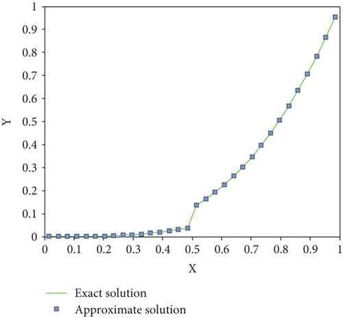
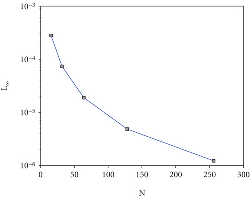
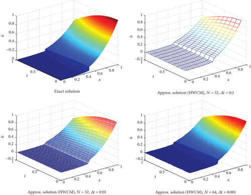
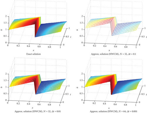
In the first two linear and nonlinear elliptic interface models, the errors are decreased to 10-6 and 10-7 even for small number of grid points. It is worth mentioning that more accurate numerical results can be obtained if we increase the number grid points. In Table 1, the absolute errors for distinct collocation points are listed. The graph given in Figure 2 also demonstrates that the proposed technique captures the discontinuity very well, where the other methods failed to do so. The computational rate of convergence of the proposed method is approaching to 2, which is theoretically confirmed by Majak et al. [42, 43]. The obtained results are compared with the immersed interface method from literature. The comparability shows that the newly proposed technique is efficient and more accurate for elliptic type interface models than the existing methods. The newly proposed numerical technique is also tested on advection-diffusion-reaction type parabolic interface models, comprising of three linear and one nonlinear models. The obtained point wise absolute errors are mentioned in Tables 3–6. The numerical results are also demonstrated through 3D visualization of the graphs listed in Figures 3 and 4. From the aforementioned figures, it is clear that the newly proposed technique handled the jump discontinuity at 0.5 and 0.7 very well. The approximate results are compared with the immersed interface method from the existing literature. The comparability shows that the proposed technique has better accuracy with simple implementation.


| J | N | Δt | Ec(N) proposed technique | CPU time in sec | N | IIM |
|---|---|---|---|---|---|---|
| 1 | 8 | 1/8 | 1.8394 × 10⁻³ | 0.279452 | 8 | 3.7 × 10⁻² |
| 2 | 16 | 1/16 | 7.7251 × 10⁻⁴ | 0.345287 | 16 | 7.1 × 10⁻³ |
| 3 | 32 | 1/32 | 3.5115 × 10⁻⁴ | 0.612788 | 32 | 1.5 × 10⁻³ |
| 4 | 64 | 1/64 | 1.6775 × 10⁻⁴ | 2.966826 | 64 | 3.0 × 10⁻⁴ |
| 5 | 128 | 1/128 | 8.1976 × 10⁻⁵ | 20.057056 | 128 | 1.0 × 10⁻⁴ |
| J | N | Δt | Ec(N) proposed technique | CPU time in sec | N | IIM |
|---|---|---|---|---|---|---|
| 1 | 8 | 0.1/8 | 1.5 × 10⁻³ | 0.395921 | 8 | 1.02 × 10⁻² |
| 2 | 16 | 0.1/16 | 7.5054 × 10⁻⁴ | 0.748104 | 16 | 2.4 × 10⁻³ |
| 3 | 32 | 0.1/32 | 3.7709 × 10⁻⁴ | 3.148897 | 32 | 6.0 × 10⁻⁴ |
| 4 | 64 | 0.1/64 | 1.8867 × 10⁻⁴ | 25.324517 | 64 | 1.0 × 10⁻⁴ |
| 5 | 128 | 0.1/128 | 9.4324 × 10⁻⁵ | 194.237104 | 128 | 1.0 × 10⁻⁴ |
| J | N | Δt | Ec(N) proposed technique | CPU time in sec | N | IIM |
|---|---|---|---|---|---|---|
| 2 | 16 | 0.001/16 | 3.6548 × 10⁻⁶ | 34.662755 | 20 | 2.9061 × 10⁻⁵ |
| 3 | 32 | 0.001/32 | 1.8282 × 10⁻⁶ | 272.116930 | 40 | 6.6497 × 10⁻⁶ |
| 4 | 64 | 0.001/64 | 9.1465 × 10⁻⁷ | 2460.769702 | 80 | 1.6343 × 10⁻⁶ |
| 5 | 128 | 0.001/128 | 4.5753 × 10⁻⁷ | 35500.767379 | 160 | 4.0802 × 10⁻⁷ |
| J | N | Δt | Ec(N) proposed technique | CPU time in sec |
|---|---|---|---|---|
| 1 | 8 | 0.1/8 | 6.0232 × 10⁻⁴ | 0.157302 |
| 2 | 16 | 0.1/16 | 1.4666 × 10⁻⁴ | 1.147091 |
| 3 | 32 | 0.1/32 | 3.3345 × 10⁻⁵ | 11.147277 |
| 4 | 64 | 0.1/64 | 6.8252 × 10⁻⁶ | 81.104287 |
| 5 | 128 | 0.1/128 | 1.3904 × 10⁻⁶ | 588.111313 |


8. Conclusion
In this article, Haar wavelet collocation technique is utilized to solve interface models comprising advection-diffusion-reaction type elliptic and parabolic models with discontinuous coefficients. The newly proposed numerical technique is applicable to both linear and nonlinear interface models. The errors are decreased up to 10-6 and 10-7 for small number of collocation points, which is supposed to be better accuracy for practical problems. The 3D graphs of the estimated and exact solutions also demonstrate that the newly proposed technique handle the jump discontinuity very well, while the other existing techniques failed to capture it. The stability and convergence of the said numerical technique are also proved in the convergence and stability sections, which made the method more powerful. The obtained results are compared with the immersed interface method. The comparability shows that the newly proposed technique is efficient and has better accuracy than immersed interface method.
Conflicts of Interest
The authors declare that there is no conflict of interests regarding the publication of this paper.
Open Research
Data Availability
No data were used to support this study.


