[Retracted] Visual Construction of Logical AND and NAND Gates
Abstract
DNA logic gates are an important branch of DNA computing and have a wide range of applications in DNA computing. In this study, logic circuits of AND gate and NAND gate are built on origami substrate. The realization of AND gate uses polymerase strand displacement (PSD) reaction and hybridization chain reaction (HCR). If there is a fluorescent band “1” displayed, the result is true. The realization of the NAND gate requires a cyclic reaction. If there is a fluorescent band “A” or “T” displayed, the result is true; if no fluorescent band is displayed, the result is false.
1. Introduction
Computer technology is considered to be one of the three major scientific revolutions in the 20th century, and electronic computers have played a huge role in promoting social development. In recent years, due to the rapid development of science and technology, traditional electronic computers have been unable to meet people’s needs. DNA computer is one of the most original and unexpected discoveries in recent years. It has the advantages of high parallelism, fast computing speed, large storage capacity, low energy consumption, and abundant DNA molecular resources. In order to create a DNA computer, people began to study DNA computing. The foremost example of DNA computing solves a seven-city Hamiltonian path problem [1]. Inspired by the idea Adleman, Lipton constructs a network graph G, maps solution space of the satisfiability problem (SAT) to all Hamiltonian paths of the starting and ending points of network graph G, and successfully solves a SAT problem [2]. Later, scholars have continuously innovated on the basis of previous studies and successfully solved the 0–1 integer programming problem [3–8], the maximum clique [9], and other complete NP problems [10,11].
With the development of biomolecule science, domestic and foreign scholars have set off a boom in research on DNA computing and achieved fruitful research results. In 1998, Winfree first proposed a bottom-up, disorder-to-order, and high-precision self-assembly model for DNA molecules [12]. On the basis of molecular self-assembly technology, Rothemund first discovered a novel DNA self-assembly technology, namely, DNA origami. The technique extracted a long single-stranded DNA from M13mp18 phage to fold into a square, triangular, pentagon, and other sophisticated planar structures [13]. After the introduction of DNA origami, scholars have successfully folded many additional structures using this technique [14–16].
DNA logic circuit is an important branch of DNA computing. Common logic circuits include AND, OR, XOR, NAND, and INHIBIT. Researchers built half adders and half subtracters based on these logic circuits [17–19]. Half adder and half subtracter are corresponding to two-bit input and two-bit output, while total adder and total subtracter are corresponding to three-bit input and two-bit output. Half adder is obtained by cascading logical AND gate and XOR gate, and a half adder is composed of a AND gate and a XOR gate. Half subtractor is obtained by logical XOR gate and INHIBIT gate, and a half subtractor is composed of a XOR gate and an INHIBIT gate.
Since DNA origami and DNA logic circuits are both important branches of DNA computing, researchers began to consider combining both, namely, studying logic circuits on DNA origami and achieved fruitful results [20–30]. In [28], Tang et al. constructed the dynamic and NAND model on DNA origami. Different logical values were mapped to different DNA input strands. By observing whether gold nanoparticles (AuNPs) are on the origami substrate to judge true and false, in the previous research results, the occurrence of leakage reaction and the limitation of space steric hindrance often appear. Here, polymerase strand displacement reaction and cyclic reaction are used to effectively solve the above problems.
In this study, a visual AND gate and a NAND gate model are designed on the DNA origami platform. The judgment result is determined by observing whether there is fluorescence on the origami platform. The truth table is given in Table 1. In the design of the AND gate, the hairpins with fluorescence and fluorescence quencher are anchored on the DNA origami platform to form a “1” structure, and the initiation strand and polymerase are set as variables. When adding different variables, observe whether there is a fluorescent band display on the origami. In the design of the NAND gate, the hairpins with two kinds of fluorescence are anchored on the origami substrate to form two kinds of fluorescent bands “A” and “T,” respectively, and the initiation strand is set as a variable. Different initiation strands are added, and a cyclic reaction occurs under the action of the auxiliary strand with a fluorescence quencher. Finally, observe whether there is a fluorescent band “A” or “T” on the origami. Throughout the reaction, the origami substrate is always in solution.
| Input 1 | Input 2 | AND | NAND |
|---|---|---|---|
| 0 | 0 | 0 | 1 |
| 0 | 1 | 0 | 1 |
| 1 | 0 | 0 | 1 |
| 1 | 1 | 1 | 0 |
The remaining of the paper is organized as follows. In Section 2, relevant reaction principles of visual logic gates are introduced. In Section 3, the visual logic gates are described. Finally, this paper is concluded in Section 4.
2. Relevant Reaction Principles of Visual Logic Gates
2.1. Principle of DNA Strand Displacement Reaction
DNA strand displacement technology refers to a process in which a single DNA strand reacts with partially complementary double strands to replace and display the constrained single strand in the original structure, thereby forming a new double strands structure. When the length of the complementary strand changes, the binding force forming the double helix structure is also different. When the DNA molecule is in the hybrid system, it gradually transitions to a state where the entropy is increasing and the free energy tends to be stable so that the input strand with stronger binding force replaces the constrained single strand with weaker binding force, and finally, the replaced single strand is the output signal, and the strand realizes the function of molecular logic operation. DNA strand displacement can be divided into reversible and irreversible situations. The reaction principle is shown in Figure 1, where A and A∗ are complementary, B and B∗ are complementary, C and C∗ are complementary.


2.2. Principle of Polymerase Strand Displacement Reaction
Polymerase strand displacement (PSD) is a polymerase-based strand displacement reaction, which is different from the general strand displacement reaction in which the reaction requires the participation of enzymes. The reaction principle is shown in Figure 2, where A and A∗ are complementary, B and B∗ are complementary, C and C∗ are complementary, and D and D∗ are complementary. This reaction is very similar to polymerase chain reaction (PCR). First, the primer and the sticky end of the partially complementary double-stranded DNA are combined according to the principle of base complementary pairing, namely, A and A∗ are combined. Besides, adjust the temperature to the optimal reaction temperature for DNA polymerase. Under the action of DNA polymerase, the primer is extended from the 3′end in the direction of 5′⟶3′ to synthesize a DNA strand complementary to the template 5′-D-C-B-A-3′, which replaces the single strand 5′- C∗-D∗-3′ from the partially complementary double-stranded DNA.

2.3. Principle of Hybridization Chain Reaction
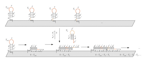
Hybridization chain reaction (HCR) is based on different types of hairpin structures. Tent and a series of T1 are anchored on the origami substrate, and the other hairpins are distributed in the solution. With the action of the starting strand, the hairpin structures are opened in sequence, until a kind of hairpin is consumed so the reaction is over. The reaction process is spontaneous and does not require the participation of enzymes. The reaction principle is illustrated in Figure 3. Tent is a hairpin structure anchored on the origami, which is also called the starting hairpin. It is composed of 5′-b-c-d-e-d∗-c∗-3′, where e is the loop of the hairpin. In the regions of the stem, c and c∗ and d and d∗ are complementary, while b is the exposed sticky end. T1 is also a hairpin structure anchored on the origami, consisting of 5′-f-c-d-e-d∗-c∗-3′, where e is the loop of the hairpin. In the stem regions, c and c∗ and d and d∗are complementary, while f is the exposed sticky end. S is the initiation strand, consisting of 5′-d∗-c∗-b∗-3′. T2 is the auxiliary strand distributed in the solution, composed of 5′-d∗-c∗-f∗-c-d-e∗-3′. Among them, f∗ is the loop of T2. In the stem regions, c and c∗ and d and d∗ are complementary, but e∗ is the exposed sticky end. First, add the initiation strand S; the b∗ area in S and the b area in Tent combine to open the hairpin structure of Tent, exposing the e-d∗-c∗ areas. The e∗ area in T2 and the exposed e area combine to open a hairpin structure of T2, exposing the d∗-c∗-f∗ area. Then, T1 hairpins are opened, and proceed in turn on the origami. With all T1 hairpins opened, the reaction is over.
3. Visual Logic Gates
3.1. Building Visualization AND Gate
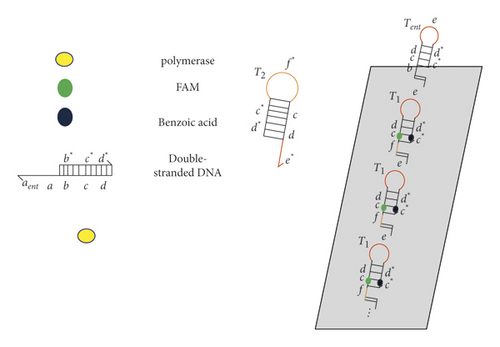
The AND gate is part of the molecular logic gates. Only when both inputs are 1, the result is true, as shown in Table 1. Here, the hairpins with green fluorescent 6-carboxyfluorescein (FAM) and fluorescence quenching agent benzoic acid are anchored on the origami. The initiating strand is replaced by PSD reaction; then, the replaced initiating strand opens other hairpins through the HCR reaction so that there is a green fluorescent band with a shape of “1” on the origami. The materials needed to build AND gate structure are as follows: a two-dimensional origami platform, hairpin structures Tent and T1, primer, auxiliary strands T2, 6-carboxyfluorescein (FAM), benzoic acid (quenching FAM), a polymerase, and partially complementary double-stranded DNA structure, as shown in Figure 4.
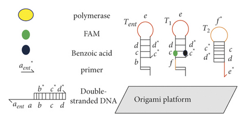
We need to anchor a Tent hairpin and a series of hairpin structures T1 on the origami platform to form a “1” shape. Tent is composed of six regions, namely, 5′-b-c-d-e-d∗-c∗-3′, where e is the loop of the hairpin. In the stem regions, c and c∗ and d and d∗ are complementary, while b is the exposed sticky end. T1 is composed of six regions, namely, 5′-f-c-d-e-d∗-c∗-3′, where e is the loop of the hairpin. In the stem regions, c and c∗ and d and d∗ are complementary, while f is the exposed sticky end. FAM is labeled on the region c of T1, and benzoic acid is labeled on the region c∗ so that T1 does not emit light on the origami platform. T2 is likewise composed of six regions, namely, 5′-d∗-c∗-f∗-c-d-e∗-3′, where f∗ is the loop of T2. In the stem regions, c and c∗ and d and d∗ are complementary, while e∗ is the exposed sticky end. The primer is a single DNA strand of 5′-aent∗-3′. The downstream single strand of partially complementary double-stranded DNA is composed of 5′-d-c-b-a-aent-3′, and the upstream single strand is composed of 5′-b∗-c∗-d∗-3′, where b and b∗ are complementary, c and c∗ are complementary, and d and d∗ are complementary. We define primer and polymerase as variables, with green fluorescent band of shape “1” showing true result and without green fluorescent band showing false result.
When the primer and polymerase are not added, namely, (0, 0). No reaction takes place in the solution. At this time, there is no green fluorescent band on the origami platform, and the output result is 0, as shown in Figure 5.
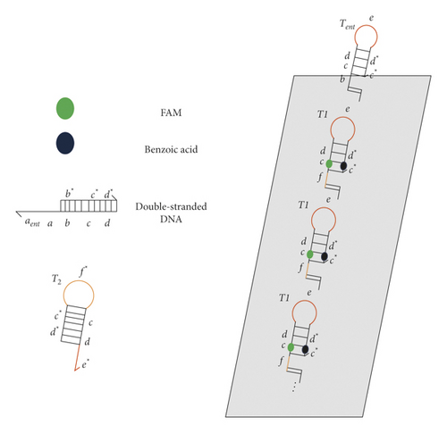
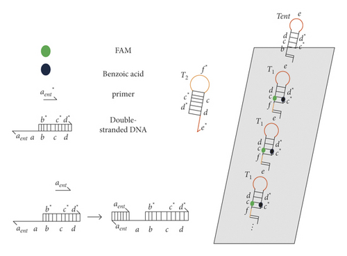
When only the primer is inputted, that is, (1, 0), the primer 5′-aent∗-3′ reacts with the partially complementary double-stranded DNA in the solution. According to the rule of base complementary pairing, the areas of aent and aent∗ are complementary. The primer is attached on partially complementary double-stranded DNA, and there is no polymerase strand displacement reaction. At this time, there is no green fluorescent band, and the output result is 0, as shown in Figure 6.
When only polymerase is inputted, that is, (0, 1), there is no reaction in the solution. At this time, there is no green fluorescent band displayed on the origami platform, and the output result is 0, as shown in Figure 7.
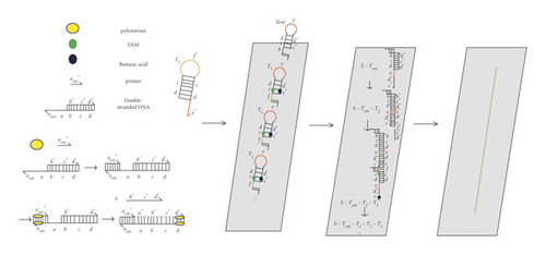
When the primer and polymerase are inputted, namely, (1, 1), the primer will first react with the partially complementary double-stranded DNA. With the help of polymerase, stand S is replaced through a PSD reaction. After that, HCR reaction will occur. The b∗ area of strand S will be combined with the b area of the hairpin structure Tent, thus opening the Tent hairpin structure to expose the e-d∗-c∗ areas. The exposed e-d∗-c∗ areas will then be combined with e∗ in T2. Opening a T2 hairpin structure to expose the d∗-c∗-f∗ areas, then the d∗-c∗-f∗ areas react with T1 and open a hairpin of T1 structure to expose the e-d∗-c∗ areas. At this time, FAM and benzoic acid phase are separated so that there are green fluorescent displays on the origami. The exposed e-d∗-c∗ areas will be combined with e∗ in another T2, opening the hairpin structure of T2 to expose the d∗-c∗-f∗ areas. Then, the exposed areas will react with a next T1, so the reaction proceeds in sequence until the T1 structures on the origami are fully opened. After that, the reaction ends. In this way, a green fluorescent band with a shape of “1” appears on the origami, the output result is 1, as shown in Figure 8.
3.2. Building Visualization NAND Gate
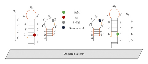
The NAND gate is a kind of combinatorial logic gate; only when the input is (1, 1), the result is 0, otherwise the output result is 1. Here, the construction of the NAND gate is to anchor two kinds of hairpin with fluorescent markers on the origami, forming two shapes of “A” and “T,” respectively. The materials needed to build NAND gate structure are as follows: an origami platform, hairpin structures of M1 with cy5 and hairpin structures of M2 with FAM, auxiliary strands M3 with BHQ3 and auxiliary strands M4 with benzoic acid (BHQ3 can quench cy5, benzoic acid can quench FAM), and initiation strands H1 and H2 which are set as input variables, as shown in Figure 9. M1 is composed of 5′-1-2-3-4-a∗-b∗-4∗-3∗-2∗-3′, where the 2 area in M1 is marked with red fluorescent cy5. Besides, a∗ -b∗ areas represent the loop of M1, 2 and 2∗ are complementary, 3 and 3∗ are complementary, and 4 and 4∗ are complementary, while area 1 is the exposed sticky end. M2 is composed of 5′-5-6-7-8-a∗-b∗-8∗-7∗-6∗-3′, where the 6 area in M2 is marked with green fluorescent FAM. Besides, a∗ -b∗ areas represent the loop of M2, 6 and 6∗ are complementary, 7 and 7∗ are complementary, and 8 and 8∗ are complementary, while area 5 is the exposed sticky end. M3 is composed of 5′-4-b-a-4∗-3∗-2∗-1∗-a∗-b∗-3′, where the 2∗ area in M3 is marked with BHQ3. Besides, 4∗-3∗-2∗-1∗ areas indicate the loop of M3, a and a∗ are complementary, and b and b∗ are complementary, while the area 4 is the exposed sticky end. M4 is composed of 5′-8-b-a-8∗-7∗-6∗-5∗-a∗-b∗-3′, where the 6∗ area in M4 is marked with benzoic acid. Besides, 8∗-7∗- 6∗-5∗ areas represent the loop of M4, a and a∗ are complementary, and b and b∗ are complementary, while the area 8 is exposed as a sticky end. The initiation strand H1 is composed of 5′-4∗-3∗-2∗-1∗-3′; meanwhile, the initiation strand H2 is composed of 5′-8∗-7∗-6∗-5∗-3′. Here, a fluorescent band on the origami is defined as 1, and no fluorescent band is defined as 0.
3.2.1. Cyclic Reaction of NAND Gate
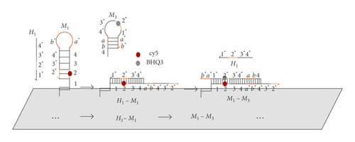
Here, a cyclic reaction is designed. As long as an initiation stand such as H1 is added, the original initiation strand is obtained through the HCR reaction so that the reaction can proceed cyclically, until the fluorescence of M1 on the origami are all quenched; then, the reaction ends. The process of reaction is shown in Figure 10.
When the initiation strand is not added, that is, (0, 0), M1 and M2 are anchored on the origami to form two shapes “A” and “T,” respectively. At this time, there are red “A” and green “T” fluorescent bands showing the output of 1, as shown in Figure 11.

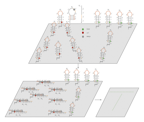
When the initiation strand H1 is inputted, namely, (1, 0), the area 1∗ in the initiation strand H1 and the area 1 in M1 combine to open a hairpin structure of M1, exposing a∗-b∗-4∗-3∗-2∗ areas. At this time, the areas of a∗-b∗-4∗-3∗-2∗ will open a hairpin structure of M3, where BHQ3 will quench cy5. After the reaction, H1 will be replaced, so H1 will continue to react with others M1 on the origami to form the abovementioned cyclic reaction. By the end of the reaction, only hairpin structures of M2 are anchored on the origami, showing a green “T”-shaped fluorescent band, the result being 1, as shown in Figure 12.
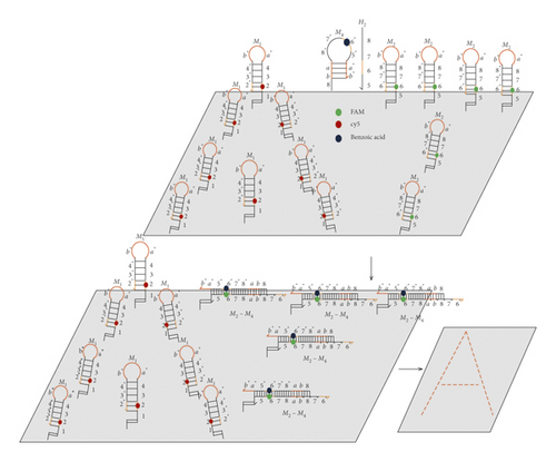
When the initiation strand H2 is inputted, namely, (0, 1), the area 5∗ in the initiation strand H2 and the area 5 in M2 are combined to open a hairpin structure of M2, exposing a∗-b∗-8∗-7∗-6∗ areas. At this time, the areas of a∗-b∗-8∗-7∗-6∗ will open a hairpin structure of M4, where the benzoic acid in M4 will quench FAM. After the reaction, H2 will be replaced which is going to interact with others M2 on the origami to form the abovementioned cyclic reaction. When the reaction is over, only hairpin structures of M1 are anchored on the origami, showing a red “A”-shaped fluorescent band. At this time, the result is 1, as shown in Figure 13.
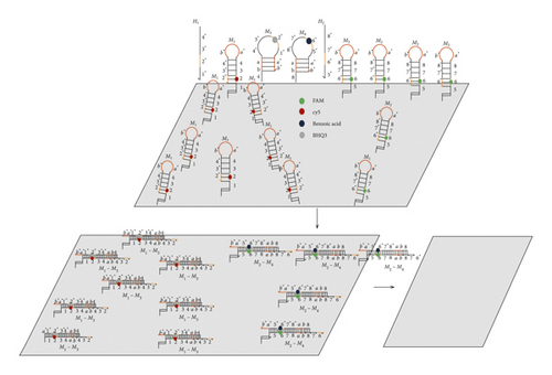
When the initiation strands H1 and H2 are inputted, namely, (1, 1), the initiation strand H1 opens a hairpin structure of M1, exposing a∗-b∗-4∗-3∗-2∗ areas. At this time, the areas of a∗- b∗-4∗-3∗-2∗ will open a hairpin structure of M3, where BHQ3 will quench cy5. After the reaction, H1 will be replaced, so H1 will continue to react with others M1 on the origami to form the abovementioned cyclic reaction. Meanwhile, the initiation strand H2 opens a hairpin structure of M2, exposing a∗-b∗-8∗-7∗-6∗ areas. At this time, the areas of a∗-b∗-8∗-7∗-6∗ will open a hairpin structure of M4, where benzoic acid will quench FAM. After the reaction, H2 will be replaced, so H2 is going to react with other M2 on the origami to form the abovementioned cyclic reaction. When all reactions are done, all the hairpins on the origami are opened. At present, the result is 0, as shown in Figure 14.
4. Conclusion
In this study, visualization AND gate and NAND gate models are constructed on origami based on PSD reaction and cyclic reaction. In the construction of the AND gate, the hairpins with fluorescence and fluorescence quencher are anchored on the origami so that there is no fluorescence band display when no primer and polymerase are added. Only when the primer and polymerase are added at the same time, the PSD reaction occurs followed by HCR reaction. The hairpins anchored on the origami are opened so that the fluorescence and the fluorescence quencher are separated. With a green “1”-shaped fluorescence band displays on the origami, in the construction of the NAND gate, a cyclic reaction is designed based on the HCR reaction. Two kinds of hairpin marked with fluorescents are anchored on the origami, forming two shapes of “A” and “T,” respectively. Two kinds of fluorescent band are displayed on the origami without adding the initiation strands. When only one kind of initiation strand is added, the corresponding fluorescent band will be quenched. However, when two kinds of initiation strand are added, there is no fluorescent band display on the origami.
The design of this study is carried out on an origami, and the results are judged by observing whether there are fluorescent bands’ displays on the origami. PSD reaction can effectively prevent the occurrence of leakage reactions. HCR reaction is spontaneous whose speed is fast. During the reaction, the enzyme is not needed. However, HCR reaction must comply with a certain directionality. The first hairpin of the reaction must have a certain specificity which will also be restricted by steric hindrance. Cyclic reaction can add the problem of steric hindrance, but its reaction speed is slow, and it is difficult to end the reaction in a short time. How to combine HCR reaction with cyclic reaction is the next problem that needs to be solved.
Conflicts of Interest
The authors have no conflicts of interest to disclose.
Acknowledgments
The project was supported by National Natural Science Foundation of China (nos. 61672001, 61702008, and 62072296) and Natural Science Foundation of Anhui Province (no. 1808085 MF193).
Open Research
Data Availability
No data were used to support this study.


