Vibration Response of the Crawler Combine Chassis Frame Excited by the Engine
Abstract
There are many problems of vibration and noise in combine working. As the main power source and excitation source of a combine, the working state of an engine directly affects the reliability and stability of the whole harvester. In order to analyze the vibration response characteristics of a chassis frame under engine excitation, the vibration mechanism and theoretical excitation characteristics of an engine vibration source on a crawler combine harvester are analyzed in this paper, and the vibration response of chassis under engine excitation is tested and analyzed. After theoretical derivation, a two-degree-of-freedom dynamic model of an engine and chassis is established. The experimental results show that the up and down vibration generated by the engine is the main vibration source in the Z direction, and the main excitation frequency is the second-order firing frequency. This paper provides a theoretical reference and experimental basis for vibration reduction and noise reduction of combine and vibration characteristics of the chassis frame.
1. Introduction
The crawler grain combine harvester is a complex large-scale agricultural harvester which integrates the functions of harvesting, threshing, separation, and cleaning [1–3]. In the field harvesting operation under complex working conditions, the vibration characteristics of the chassis frame under multisource excitation are complex and changeable, which will affect the reliability and operation safety of the whole machine in field harvesting [4–6]. The vibration of the whole machine is large, the parts are easy to be damaged, and the reliability of the whole machine is low, which seriously affects harvest efficiency and the physical and mental health of drivers and brings immeasurable losses to farmers [1].
The combine chassis is one of the main parts of the whole machine, bearing the engine and other parts. In the working process, the vibration of the chassis frame is caused by excitation of the road surface and the effect of other parts, and then, the whole frame will appear to have obvious vibration. Severe vibration will reduce the reliability of the combine, leading to fatigue damage of the chassis frame, and ultimately affect the working efficiency of the whole machine [7–9]. Türkay and Akçay studied the random dynamic vibration characteristics of a 1/4 vehicle model and pointed out the influencing factors of vehicle random vibration [10]; Mareta et al. established the vibration model of a 1/4 vehicle suspension system, derived the vibration differential equation, and studied the vibration isolation performance of the vehicle suspension system by inputting typical vehicle parameters [11]; Shehata et al. used MATLAB/Simulink to solve the mathematical model and motion equation of the quarter vehicle suspension system [12]; Karaoglu and Kuralay carried out stress analysis and experimental research on the truck chassis frame based on the finite element analysis software and optimized the structural parameters of the frame [13]; Chen et al. took the rice combine as the research object. Based on the multisource excitation of the combine, the chassis frame and thresher were assembled into a complete combined harvester frame. The vibration response of the combine frame under the multisource excitation was deduced, and the dynamic model of the combine frame with a 7-DOF rigid body was established. On this basis, the dynamics was developed in MATLAB simulation analysis of excitation parameters and vibration response of the model [14].
As the power source of the combine, the structural mode, mechanical characteristics, and kinematic characteristics of the engine have a great impact on the vibration of the combine. Its excitation effect is an important reason for the fatigue failure of the combine frame. Therefore, it is particularly important to study excitation characteristics of the engine vibration source of the combine harvester. In recent years, scholars domestically and internationally have carried out some research work on structural dynamics and modal of various vibration sources of harvesting machinery. Ebrahimi et al. carried out vibration modeling and modification on the header in harvesting through operational modal analysis (OMA) and carried out dynamic analysis on the header by using the finite element model. The test results show that the modal parameters (natural frequency) predicted and measured are mutually verified [15]; Heylen et al. have studied the fatigue linear cumulative damage mechanism through load time history and load spectrum [16]; Kumar et al. used ANSYS modal analysis which was carried out on the vehicle gearbox to obtain its natural frequencies and vibration modes [17]; Chandru et al. revealed the relationship between the frame vibration and its fixed constraints by comparing the modal analysis results of the transmission frame under different constraint conditions [18].
In this paper, the chassis frame of a crawler combine is taken as the research object. The vibration theory and field test are combined to study the vibration coupling between the engine variable load and the main frame in the harvesting of the crawler combine and explore the vibration mechanism and response of the chassis frame of the crawler combine under the excitation of the engine. According to the structural characteristics and working characteristics of the engine, the dynamic model is established. The vibration test of the chassis and the engine under multiple working conditions is carried out, and the vibration response is analyzed. It not only provides the theoretical basis for the vibration mechanism research of the crawler combine but also provides the experimental basis for vibration response research of the chassis. It also has a certain reference value for the vibration reduction and noise reduction and structure optimization of the harvester.
2. Establishment of the Dynamic Model of the Vibration System
2.1. Establishment of the Engine Dynamic Model
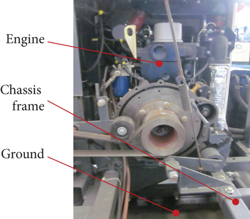
The engine is the power source of the crawler combine. The periodic thrust produced by high-temperature and high-pressure gas combustion and the unbalanced inertia force of crank-connecting rod mechanism movement are the main incentives to the outside world, which are transmitted to the chassis frame and the whole machine through the mounting bracket and transmission system. The most effective way to reduce the vibration of the combine harvester is to reduce the vibration amplitude. Most of the existing crawler combine engines are four-cylinder in-line engines, that is, linear combination of four single-cylinder engines.
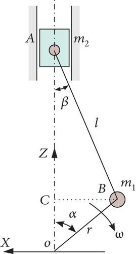
When the gas in the engine does the work stroke, the high-temperature and high-pressure gas pushes the piston A to move down the track, so that the crank is driven to rotate around the axis of O point through the connecting rod, and the driving force is output outwards. When the engine is in other stroke, the unbalanced inertia force of a crankshaft can still drive piston A to move up and down, but its angular velocity ω changes. In order to facilitate further analysis, the mechanical model of the single-cylinder engine of the crawler combine is established, as shown in Figure 1(a) [19].
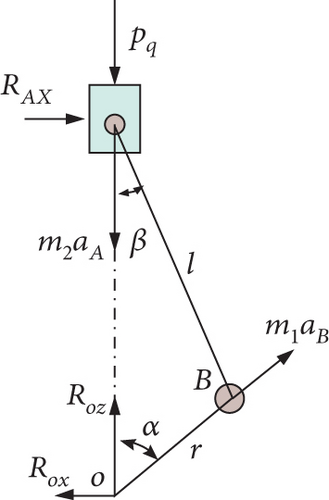
In addition, the high-temperature and high-pressure gas in the engine cylinder also acts on the engine cylinder head, producing periodic shock signal. This shock signal, which includes the forces Pq, ROX, ROZ, and RAX, is also transmitted to the chassis frame through the engine mount bracket.
It can be seen from equation (14) that the block of the 4-cylinder engine is only affected by the second-order component of the Z-direction of gas pressure and inertial force, and the first-order component and X-direction force are balanced [21].
2.2. Vibration Excitation Force Generated by the Engine
2.3. Vibration Model of the Chassis Frame under Engine Excitation
The functionality and practicability of the crawler combine determine the complexity of its transmission structure and components. In order to analyze the vibration characteristics of the system, the main frame of the crawler combine is equivalent to a mechanical mathematical model, and the components on the main frame are discretized into equivalent rigid bodies with certain mass. The connection mode of the components is composed of several damping devices and springs. Then, the vibration system can be represented by the linear system with multiple degrees of freedom.
In a multidegree-of-freedom system, the relative position of each component needs more independent coordinates to define accurately. There are many vibration sources and complex transmission system of crawler combines. When studying the vibration characteristics of the main frame and each vibration source, we should add as many degrees of freedom as possible to simulate the actual working state of the whole machine, so as to obtain more accurate simulation results. However, when there are too many degrees of freedom of the frame vibration system, the simulation process will become very complex [24–26], and it is difficult to accurately define the amplitude of each simulation parameter.
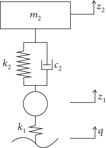
Therefore, the reasonable definition and planning of a multidegree-of-freedom vibration model of the crawler combine frame and vibration source are of great significance to the vibration mechanism, vibration response research, vibration reduction, and noise reduction of the chassis. When studying the vibration system composed of the chassis frame and engine, they can be simplified into the simplest and most classical two-degree-of-freedom vibration model, as shown in Figure 2.
The main parameters and meanings in the figure are as follows: m1 is the chassis frame mass (kg), m2 is the engine mass (kg), k1 is the connection stiffness between the chassis frame and the track (N/m), k2 is the stiffness of the engine mounting bracket (N/m), c2 is the damping of the engine mounting bracket (N·s/m), z1 is the displacement vector of the chassis frame in the system (m), z2 is the displacement vector of the engine (m), and q is the roughness function of the field pavement.
3. Vibration Test and Characteristic Analysis of the Engine and Chassis Frame
The excitation action of the engine is transmitted to the chassis frame on the engine support, which causes vibration. The vibration of the frame depends on the RMS value of the amplitude, the main frequency, and the power spectral density. The experimental data is mainly analyzed in the time domain and frequency domain, so as to study the vibration characteristics of the chassis frame under different working conditions.
3.1. Engine and Chassis Vibration Test
The vibration response of a machine is usually characterized by motion, that is, displacement, velocity, and acceleration. Considering the simple and clear relationship among the three and the fact that the frequency response range of the accelerometer is large and the sensitivity is high, it is suitable for the acquisition of combine test signal [30]. The instrument used in the test is the DH5902 vibration test and analysis system and three-way acceleration sensor. During the test, five main measuring points are arranged on the chassis frame of the combine, among which the engine bracket is the vibration source measuring point, and four measuring points are arranged on the chassis frame, namely, left front, left rear, right front, and right rear. The specific numbers are shown in Table 1. In the test, the continuous random sampling method is adopted to collect the vibration acceleration signals in three directions of each measuring point. According to the sampling theorem, the sampling frequency should be at least twice of the analysis signal frequency. Therefore, the sampling frequency is set at 2.56 kHz and the sampling time is 30 s.
| Measuring point | Installation position | Measuring point | Installation position |
|---|---|---|---|
| 1 | Engine bracket | 2 | Chassis frame left rear |
| 3 | Chassis frame left front | 4 | Chassis frame right front |
| 5 | Chassis frame right rear |
In the test, the forward direction of the whole machine is the X-positive direction, the lateral direction is the Y-positive direction, and the vertical ground upward is the Z-positive direction. Then, according to the different operating conditions of the engine and the working state of the whole machine, four experimental conditions are set up; namely, the whole machine is in a static and no-load state (only the engine is working and the accelerator is small), the whole machine is in a static and no-load state (parts working, small throttle), the whole machine is moving (only engine working, large throttle), and the whole machine is moving (parts working, large throttle), as shown in Table 2.
| Test conditions | Combine running status | Testing environment | Travel speed (km/h) |
|---|---|---|---|
| 1 | The whole machine is in the static and no-load state (only the engine is working and the accelerator is small) | Cement pavement | 0 |
| 2 | The whole machine is in the static and no-load state (parts working, small throttle) | Cement pavement | 0 |
| 3 | The whole machine is running (only engine working, large throttle) | Rice field | 20 |
| 4 | The whole machine is running (parts working, large throttle) | Rice field | 20 |
3.2. Analysis of Engine Vibration Source Characteristics
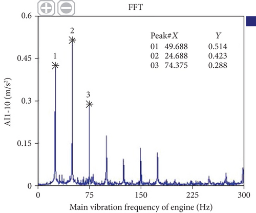
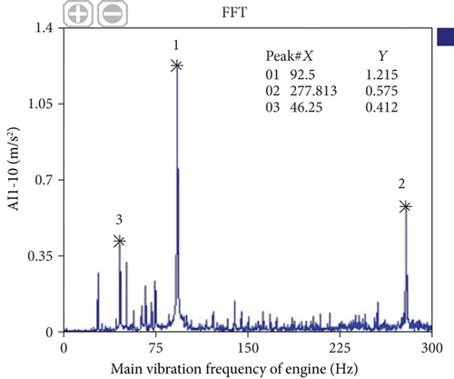
It can be seen from Figures 3 and 4 that the main vibration frequency of the engine at idle speed is 49.688 Hz, which is close to the calculated second-order frequency multiplication (50 Hz); under the condition of idling and large throttle, the main vibration frequency is 92.5 Hz, which is close to the second-order frequency multiplication (90 Hz) of the 2700 r/min engine under idle speed and large throttle condition, indicating that the vibration test results are consistent with the calculated values; the second-order firing frequency is the main vibration frequency of the engine. In addition, there are different order frequency components in the engine under the two working conditions.
3.3. Time Frequency Domain Analysis of Chassis Vibration
| Measuring point | Root mean square value of vibration acceleration (m/s2) | |||||||||||
|---|---|---|---|---|---|---|---|---|---|---|---|---|
| Condition 1 | Condition 2 | Condition 3 | Condition 4 | |||||||||
| X direction | Y direction | Z direction | X direction | Y direction | Z direction | X direction | Y direction | Z direction | X direction | Y direction | Z direction | |
| 1 | 0.90 | 1.25 | 1.64 | 2.32 | 2.14 | 3.64 | 2.67 | 2.93 | 3.89 | 6.35 | 4.72 | 13.28 |
| 2 | 0.57 | 0.74 | 0.55 | 2.83 | 2.15 | 5.36 | 2.13 | 3.89 | 5.89 | 4.37 | 4.96 | 9.36 |
| 3 | 0.62 | 0.82 | 0.87 | 2.47 | 2.71 | 4.23 | 3.45 | 2.83 | 4.03 | 4.12 | 5.58 | 5.68 |
| 4 | 0.84 | 1.02 | 1.05 | 2.06 | 2.01 | 2.35 | 3.50 | 3.64 | 9.01 | 4.59 | 5.17 | 10.08 |
| 5 | 0.68 | 0.79 | 0.98 | 2.87 | 3.23 | 3.89 | 2.67 | 9.17 | 6.44 | 3.32 | 12.25 | 9.97 |
It can be seen from Table 3 that when the total vibration of each measuring point is maximum, the combine harvester is in the working condition of the whole machine walking (parts working), while the amplitude is minimum under the working condition of the whole machine at a static and no-load state (only the engine is working and the small throttle is working). Compared with conditions 2 and 4, it can be seen that the vibration intensity of each measuring point on the chassis frame is significantly enhanced when all components are working, which may be due to the vibration coupling or resonance between the engine and other vibration sources. In addition, compared with conditions 2 and 4 or conditions 1 and 3, there are large amplitude differences between them, which indicates that the excitation of the field road surface cannot be ignored.
First of all, according to the time-domain curve of each measuring point in Figure 5 when the engine is working at idle speed and small throttle, it can be seen that the time-domain curve of each measuring point has the same periodic change as that of the engine under this condition, and the amplitude change is not obvious with time, which is relatively stable. The vibration amplitude of the seat is larger than that of the engine support, and the amplitude can reach 3.50 m/s2. In addition, the main frequency of vibration at the seat is the high frequency component, and the period related to engine speed accounts for a small proportion.
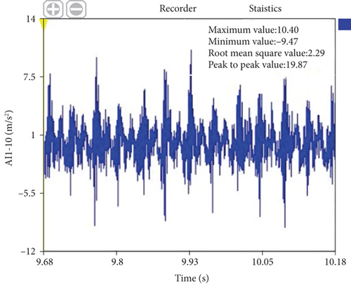
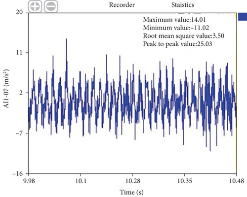
Fourier transform is applied to the time-domain signal of each measuring point. Table 4 shows the first three main vibration frequencies of each measuring point. It can be seen that the main frequency of each measuring point is basically close to the second harmonic frequency of engine speed, and there are also peaks at the fourth frequency and the fundamental frequency. The amplitude of the excitation force generated by the engine to the seat and chassis is higher, and the vertical amplitude of the seat is even 2.85 m/s2, which indicates that the two parts are greatly affected by the engine.
| Measuring point | Peak serial number | X direction (front and back) | Y direction (lateral) | Z direction (vertical) | |||
|---|---|---|---|---|---|---|---|
| Frequency (Hz) | Amplitude (m·s-2) | Frequency (Hz) | Amplitude (m·s-2) | Frequency (Hz) | Amplitude (m·s-2) | ||
| Engine mount | 1 | 49.38 | 0.71 | 49.38 | 0.55 | 49.38 | 2.28 |
| 2 | 25 | 0.68 | 25 | 0.37 | 25 | 0.40 | |
| 3 | 74.38 | 0.35 | 51.88 | 0.18 | 74.38 | 0.27 | |
| Seat support | 1 | 49.38 | 0.911 | 49.38 | 1.021 | 49.38 | 2.855 |
| 2 | 25 | 0.717 | 25 | 0.222 | 25 | 0.682 | |
| 3 | 125 | 0.633 | 49.81 | 0.197 | 98.76 | 0.485 | |
| Front left chassis | 1 | 48.75 | 1.35 | 24.38 | 0.42 | 24.38 | 1.50 |
| 2 | 24.38 | 1.00 | 51.25 | 0.33 | 51.25 | 0.76 | |
| 3 | 27.5 | 0.95 | 26.88 | 0.24 | 27.5 | 0.52 | |
When the engine works for 25 s (1500 rpm) under the condition of a small throttle and then switches to 2700 rpm at a large throttle, draw the time-frequency waterfall diagram of Z-direction vibration of each measuring point, as shown in Figure 6.
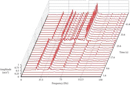
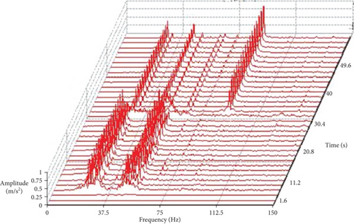
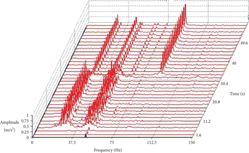
It can be seen from Figure 6 that the main frequency of each measuring point is basically the second and fundamental frequency of engine speed. The vibration amplitude of the engine fluctuates slightly, and the vibration amplitude of the second harmonic frequency of each measuring point has a period fluctuation of about 6 s. In addition, there are some peaks at 28 Hz and 74.38 Hz, which may be caused by structural resonance or rotating engine.
4. Conclusion
- (1)
In this paper, the vibration characteristics of the engine vibration source of the crawler combine are analyzed theoretically. According to the structure characteristics and working characteristics of the engine, the dynamic model is established. The vibration mechanism and theoretical excitation characteristics are further analyzed, and the expression forms of the excitation force are listed. According to Newton’s second kinematic law, a two-degree-of-freedom dynamic model of the engine and chassis is established
- (2)
The vibration response tests of the chassis frame under four working conditions are carried out. The results show that the influence of the engine on the vibration of the chassis frame is more complex. When the whole machine parts are in a working state, the vibration of the chassis frame is the largest, and the most severe vibration is at the left rear of the chassis and the seat. Therefore, it can be considered to strengthen the support at this position to improve the long-term reliability of the chassis frame and then improve the reliability of the whole machine
- (3)
The main excitation frequency of the engine to the chassis frame is the second-order firing frequency. Compared with different working conditions, the amplitude of the engine under large throttle condition is significantly greater than that under small throttle condition, and the impact signal with larger amplitude will be generated at the moment of starting and state change
Conflicts of Interest
The authors declare that they have no conflicts of interest.
Authors’ Contributions
Taibai Xu designed the study, performed the research, analyzed the data, and wrote the paper. Dongju Gao designed the study and performed the research. Yi Chen analyzed the data and wrote the paper. Weiwei Zhang analyzed the data and contributed to the revision. Fei Xu and Peng Zhou contributed to the revision.
Acknowledgments
This research work was supported by research on quality inspection technology of agricultural machinery manufacturing process of National Key R&D Plan (2017YFD0700203), National Key R&D Plan intelligent rice wheat combined harvest technology and equipment R&D (2016YFD0702003), and a project funded by the priority academic program development of Jiangsu Higher Education Institutions (No. PAPD-2018-87).
Open Research
Data Availability
The data used to support the findings of this study are available from the corresponding author upon request.


