Study on Inhibitory Effect of Cavity on Gas Explosion Propagation
Abstract
It is pointed out in the literature that the vacuum chamber has the effect of explosion suppression. The effect of explosion suppression depends on the volume of the vacuum chamber, while the vacuum degree has little effect on the performance of explosion suppression. Inspired by this, to explore a new method of gas explosion suppression, a rectangular steel cavity with a wall thickness of 10 mm, a length of 500 mm, a width of 800 mm, and a height of 200 mm was designed. The cavity was installed in a pipeline system to carry out experimental research and to investigate the law of attenuation of gas explosion flames and shock wave overpressure after passing through the cavity. The results show that the single cavity has the function of flame-out and wave attenuation, which attenuates the explosion flame and shock wave overpressure by 42.5% and 11%, respectively, and that the dual cavity further improves the performance of flame-out and wave attenuation, which attenuates flame and shock wave overpressure by 75.4% and 26.7%, respectively. On the basis of the experimental study, a numerical model was established, and a numerical simulation was carried out under the same conditions as the experimental study. The results show that the single cavity inhibits the propagation of the shock wave and attenuates the shock wave overpressure by 10.61%. The dual cavity further improves the suppression performance and attenuates the shock wave overpressure by 28.88%. Finally, by simulating the propagation process of the gas explosion shock wave and flame in the cavity, the mechanism of inhibiting gas explosion propagation by the cavity structure is analyzed.
1. Introduction
In recent years, gas accidents have accounted for more than 70% of the major accidents in coal mines in China, among which gas explosions are the main type of gas accident [1]. Therefore, it is of great scientific significance and application value to study and promote the development of gas explosion flameproofing and suppression technology. Scholars have carried out numerous experimental studies and theoretical explorations. The results of studies in [2–16] showed that a series of achievements have been made in the research of explosion inhibitors such as water mist, powder, and inert gas. In [ 17, 18], it was determined on the basis of experiments that porous materials have the effect of reducing shock wave overpressure and inhibiting flames. Wu et al. [19] designed a vacuum chamber, which is installed on the side wall of the experimental pipeline. When the explosion occurred, the diaphragm between the pipeline and vacuum chamber broke. Because of the negative pressure in the vacuum chamber, the explosion flames and shock waves were inhaled into the vacuum chamber. Shao et al. [20, 21] found that the explosion suppression effect of the vacuum chamber depends on the relationship between the vacuum volume and the critical volume. When the volume of the vacuum chamber is larger than the critical volume, the vacuum chamber has a good explosion suppression effect. For a vacuum chamber volume that is less than the critical volume, the vacuum chamber has no explosion suppression effect; however, the explosion pressure and flame strength are stronger than those without a vacuum chamber, and the vacuum level has no obvious effect on the explosion suppression. The above studies mainly focus on explosion inhibitors, energy absorbing materials, and vacuum chamber. However, in practical applications, there are some shortcomings, such as unstable system performance, poor timeliness, a large maintenance workload, and high cost.
Inspired by the explosion suppression effect of the vacuum chamber whose effect of explosion suppression depends on the volume of the vacuum chamber, the vacuum degree has little effect on the performance of explosion suppression. In this study, a rectangular cavity with a length of 500 mm, a width of 800 mm, and a height of 200 mm was designed, and a single cavity and a dual cavity were laid, respectively, between two experimental pipelines to explore a new method of gas explosion propagation suppression which is of low maintenance costs and resistant against repeated explosion damage. Through experimental research and numerical simulation, the inhibitory effect of cavities on explosion shock waves and flame propagation was studied, and the suppression mechanism of gas explosion propagation under effect of cavity was discussed.
2. Experimental Study on the Inhibitory Effect of Cavity on Gas Explosion Propagation
A rectangular cavity with a length of 500 mm, a width of 800 mm, and a height of 200 mm was installed in a large gas explosion experimental pipeline. To carry out experiments on the influence of gas explosion propagation by a single cavity or dual cavity separately, the shock wave overpressure and flame data were analyzed. Compared with the experimental data of gas explosions in a straight pipeline without a cavity, the effect of cavities on propagation of gas explosion flame and shock wave was analyzed.
2.1. Experimental System
As shown in Figure 1, the length of the explosion experimental pipeline system is 36 m. The experimental system consists of five parts: the pipeline system, the ignition system, the gas preparation system, the explosion suppression device, and the data acquisition system.
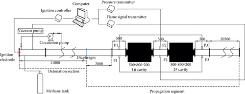
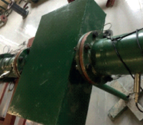
(1) The pipeline system is made of stainless steel pipe with a diameter of 200 mm and a thickness of 10 mm. The compressive strength was 20 MPa, and the pipe was connected by a flange and rubber ring to ensure the air tightness of the system. (2) The ignition system is composed of a fuse, electrode, wire, and power supply. The electrode was installed on the flange at the closed end of the experimental system. The ignition is by electric fuse, and the ignition energy is 10 J. (3) The gas preparation system is composed of an air compressor, a vacuum pump, a gas cylinder, a digital pressure gauge, and a circulating pump. The experiment used high-purity methane gas of 99.99% purity. (4) The explosion suppression device is a cavity or a combination of cavities. According to the research of Wu and Jiang [20] on vacuum cavities, considering the difficulty of underground construction and support in coal mines, the size of the cavity should not exceed four times the width of the roadway. The cavity was designed to have a rectangular structure with a length of 500 mm, a width of 800 mm, a height of 200 mm, and a cavity wall thickness of 10 mm, as shown in Figures 2. (5) The data acquisition system is composed of a pressure sensor, a flame sensor, a transmitter, a data collector, and a working host. A high-frequency dynamic pressure transmitter was adopted as a pressure sensor with an accuracy grade of 0.5% FS and a measuring range of 0–3 MPa, which is placed at 13.25 m, 14.25 m (0.25 m from the outlet of 1# cavity), and 15.25 m (1.25 m from the outlet of 1# cavity), respectively, from the ignition electrode. A photoelectric sensor was adopted as a flame sensor with a precision grade of 0.1% FS and a maximum sampling rate of 20 Msps. The installation position of the flame sensor corresponds to that of the pressure sensor.
2.2. Experimental Process
Before the experiment, the pipes were connected, and the air tightness was checked. The detonation section was sealed with a polyethylene film of thickness 0.4 mm at 11 m from the ignition electrode. The detonation section was then vacuumed by a vacuum pump. Gas preparation was realized by using the Dalton partial pressure method. In each experiment, the methane concentration was 10%, at which the methane explosion intensity was the highest [22]. After gas preparation was completed, the mixture of methane-air in the detonation section was circulated for 10–20 min using a circulating pump to uniformly mix the methane with air. Next, the valves were closed, and the methane–air mixture ignited, exploding. The flame and pressure data were obtained using flame sensors and pressure sensors. After every experiment finished, the pipeline was swept using an air compressor with positive pressure to remove the gas produced in the explosion in the pipeline.
The experiments focused on studying the inhibition effect of cavities on gas explosion propagation, which were conducted with three different scenarios. Scenario (1): gas explosion propagation experiment in a straight pipeline without a cavity. Before the experiment, cavity 1# and cavity 2# in Figure 1 were replaced with a pipe with a diameter of 200 mm and a length of 500 mm. Scenario (2): gas explosion propagation experiment with a single cavity. Before the experiment, cavity 2# in Figure 1 was replaced with a pipe with a diameter of 200 mm and a length of 500 mm. Scenario (3): gas explosion propagation experiment with a dual cavity.
2.3. Experimental Results and Analysis
The flame intensity can be expressed as S, which is equal to the integral value of the light signal collected by the flame sensor on the time axis, and the flame attenuation rate can be expressed by the formula ΔS/SF1, where ΔS is the attenuation value of the flame intensity when the explosion flame reaches the measuring point F2 (F3) passing through the measuring point F1, and SF1 is the flame intensity at the measuring point F1. The rate of overpressure attenuation can be expressed as ΔP/P1, where ΔP is the attenuation value of the maximum overpressure when the shock wave reaches P2 (P3) passing through measuring point P1, and P1is the maximum overpressure value at measuring point P1.
2.3.1. Characteristics of Gas Explosion Flame and Shock Wave Propagation in the Straight Pipeline without a Cavity
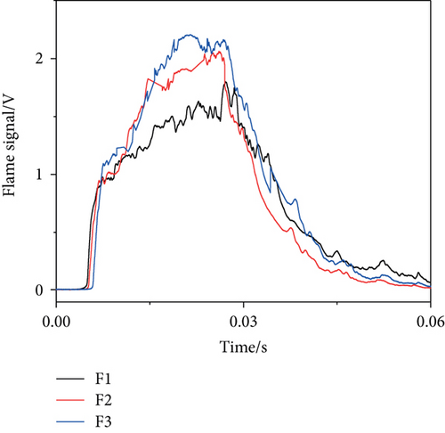
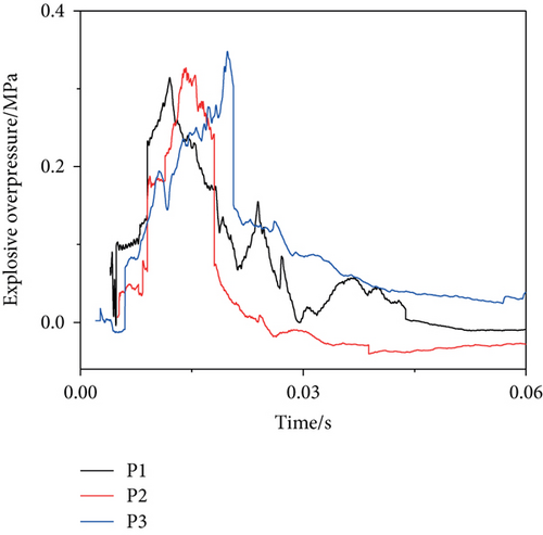
The variation curve of the explosion flame and overpressure with time at each measuring point in the straight pipeline without a cavity is shown in Figure 3. As shown in Figure 3(a), the values of the flame intensity measured for measuring points F1, F2, and F3 were 0.04717, 0.04995, and 0.05375, respectively, and the flame attenuation rates were -5.89% at F2 and -13.95% at F3, which indicates that the explosion flame intensity was enhanced. As shown in Figure 3(b), the maximum overpressures at P1, P2, and P3 are 0.31473, 0.32783, and 0.34485, respectively. The attenuation rates of overpressure at P2 and P3 were -4.16% and -11.2%, respectively, which indicates that explosion overpressure was enhanced. The explosion flame and the maximum overpressure in the pipe section where the measuring points are installed were strengthened, because the explosion chemical reaction is in the accelerated stage, and the explosion pressure is in the rising stage in the process of gas explosion propagation in the pipe section.
2.3.2. Effect of Single Cavity on Gas Explosion Flame and Shock Wave Propagation
The variation curve of the explosion flame and shock wave overpressure with time at each measuring point under the effect of a single cavity is shown in Figure 4. As shown in Figure 4(a), the flame before its entry into the cavity is stronger, and its intensity falls sharply after passing through the cavity with the occurrence of a secondary flame. The flame intensities at F1 and F2 are 0.05527 and 0.02868, respectively, and the flame attenuation rate at F2 was 48.1%. It can be seen in Figure 4(b) that the shock wave overpressure before entering the cavity is higher and drops after it passes through the cavity with the occurrence of larger secondary overpressure. The maximum overpressure at P1 and P2 is 0.3363 and 0.2918, respectively, and the attenuation rate of overpressure at P2 was 13.23%. The explosion flame and shock wave overpressure are attenuated after passing through a single cavity.
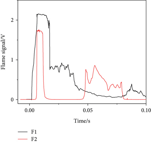

Compared with that in the straight pipeline without a cavity, the flame intensity at F1 and F2 under the effect of a single cavity is attenuated by -17.1% and 42.5%, respectively, and the shock wave overpressure at P1 and P2 is attenuated by -6.8% and 11%, respectively. The explosion flame and shock wave overpressure were enhanced at the inlet of the cavity, but were obviously attenuated at the outlet of the cavity, because the shock wave and flame expand and dissipate after entering the cavity, part of the explosion flame and shock wave outgo from the cavity through the outlet, and the other part is blocked by the cavity walls when they propagate towards the outlet. Therefore, The single cavity has an obvious inhibitory effect on the gas explosion propagation.
2.3.3. Effect of Dual Cavity on Gas Explosion Flame and Shock Wave Propagation
The variation curve of the explosion flame and shock wave overpressure at each measuring point with time is shown in Figure 5. As shown in Figure 5(a), the explosion flame is stronger before entering the cavities and sharply decreases after passing through the dual cavity, accompanied by a secondary flame. The flame intensities measured at F1 and F3 are 0.05487 and 0.01226, respectively, and the flame attenuation rate at measuring point F3 was 77.6%. It can be seen in Figure 5(b) that the shock wave overpressure is larger before entering the cavities and sharply decreases after passing through the dual cavity. The maximum overpressure at measuring points P1 and P3 is 0.3234 and 0.2403, respectively, and the attenuation rate of overpressure at the measuring point P3 is 25.7%. It can be seen that the explosion flame and shock wave overpressure are greatly attenuated after passing through the dual cavity.
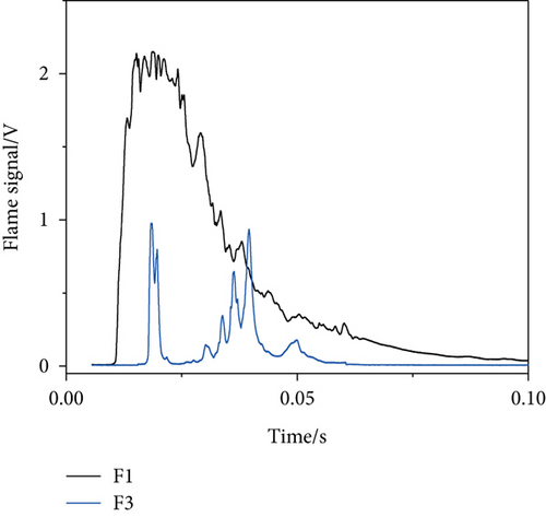
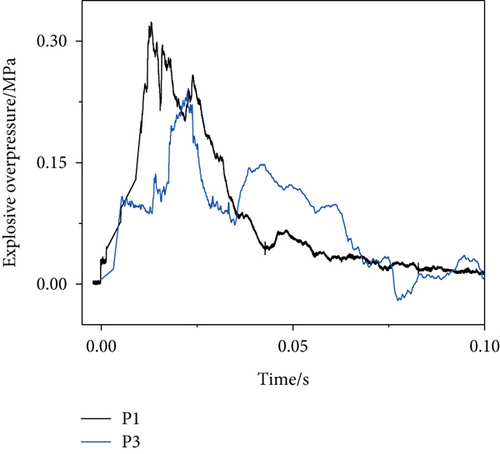
Compared with the experiments in the straight pipeline without a cavity, the flame at measuring points F1 and F3 under the effect of the dual cavity is attenuated by -16.3% and 75.4%, and the shock wave overpressure decreases by -2.76% and 26.7%, respectively. The explosion flame and shock wave overpressure were slightly enhanced at the inlet of the dual cavity, but significantly attenuated at the outlet of the dual cavity. Compared with the attenuation of explosion flame and shock wave overpressure under the effect of a single cavity, the dual cavity further improves the inhibition of gas explosion propagation.
3. Numerical Study on the Inhibitory Effect of Cavity on Gas Explosion Propagation
In order to explore the effect of cavities on gas explosion propagation, a numerical model was established based on experimental research to simulate the gas explosion propagation process in a straight pipeline without a cavity, with a single cavity, or with a dual cavity.
3.1. Geometric Model and Boundary Conditions
Figure 6 shows the geometric model and mesh division. The sizes in the directions of X, Y, and Z of the calculated area are 0.8 m, 36 m, and 0.2 m, respectively, and the number of grids is 40, 1800, and 10, respectively. The part of the pipeline at the left side of cavity 1# is a detonation section with an outer diameter of 0.2 m and a length of 11 m. The premixed gas of methane–air containing a methane concentration of 10% was filled, and the stabilized propagation section with an outer diameter of 0.2 m and a length of 2.5 m is located between the detonation section and cavity 1#. The propagation section with an outer diameter of 0.2 m is located at the right side of the 2# cavity. The total length of the dual cavity combination and propagation section is 22.5 m. In the pipeline, three monitoring points, P1, P2, and P3, were set, which are located at 13.25 m, 14.25 m (0.25 m from the outlet of the 1# cavity), and 15.25 m from the ignition electrode (0.25 m from the outlet of the 2# cavity), respectively. In the simulation with a straight pipeline without a cavity, cavity 1# and cavity 2# are replaced by a round pipe of equal diameter and equal length. In the simulation with a single cavity, cavity 2# is replaced by a round pipe of equal diameter and equal length. The locations of the monitoring points remain unchanged.

The initial conditions were as follows: the initial pressure in the pipeline was 0.1 MPa, the initial density gradient was 0, and the initial temperature was 293 K.
The boundary conditions are as follows: the pipe and cavity inner walls are adiabatic and do not slip.
3.2. Mathematical Models and Numerical Methods
It is assumed that the gas explosion process is the adiabatic expansion process of the ideal gas, ignoring the thermal radiation during the explosion propagation and the fluid-solid coupling effect between the solid wall and the impact flow, and assuming that the gas explosion process is a single-step reversible process.
The wall function method is used to deal with the change in the flow field near the wall, and the k-ɛ turbulence model was used to describe the turbulence changes during combustion. The control volume integration method, SIMPLE algorithm, and staggered grid technique are used to realize the separated solution of the coupled pressure field and velocity field. The backward difference method and incremental method are used to realize the discrete forms [24] of the control equations of the material structure field, chemical reaction field, and chemical rheological field.
3.3. Discussion on Numerical Simulation Results of Gas Explosion Propagation under Effect of a Cavity
3.3.1. Numerical Simulation Results
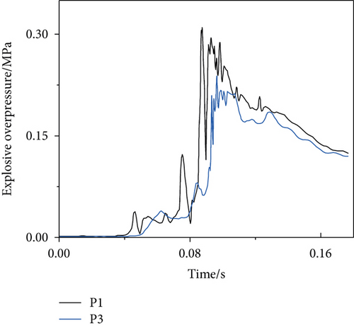
The evolution curves of the gas explosion shock wave overpressure at each measuring point in a straight pipeline without a cavity, with a single cavity, or with a dual cavity are shown in Figure 7.Compared with the experimental results, the numerical simulation values of the shock wave overpressure at each measuring point in a straight pipeline without a cavity, with a single cavity, or with a dual cavity are slightly smaller. The reason is that in the experiment, the turbulence resulting from the polyethylene diaphragm installed between the detonation section and the propagation section is broken, and the imperfect smoothness of the pipe’s inner walls and flatness at the connection of the pipe with the cavity accelerates the explosion reaction.
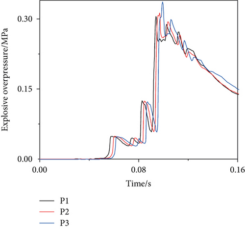
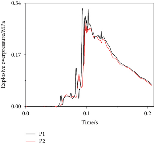
It can be seen in Figure 7(a) that the maximum shock wave overpressure at measuring points P1, P2, and P3 is 0.3053, 0.3128, and 0.3366, respectively, and the attenuation rate of the shock wave overpressure at measuring points P2 and P3 is -2.46% and -10.25%, respectively.
It can be seen in Figure 7(b) that the maximum shock wave overpressure decreases obviously after the shock wave passing through the cavity, the maximum shock wave overpressure at monitoring points P1 and P2 is 0.3241 and 0.2796, respectively, and the attenuation rate of the shock wave overpressure at P2 is 13.73%. Compared with that at the corresponding measuring points in a straight pipeline without a cavity, the overpressure at the inlet and outlet of the single cavity is attenuated by -6.16% and 10.61%, respectively. Although the overpressure at the inlet is slightly enhanced, the overpressure at the outlet is obviously attenuated.
It can be seen in Figure 7(c) that the maximum shock wave overpressure at monitoring points P1 and P3 is 0.31 and 0.2394, respectively, and the attenuation rate of the shock wave overpressure at P3 was 22.77%. Compared with that at the corresponding measuring points in a straight pipeline without a cavity, the overpressure at the inlet and outlet of the dual cavity is attenuated by -1.54% and 28.88%, respectively, which at the inlet is slightly enhanced, and at the outlet is greatly attenuated.
The experimental and simulated results of the attenuation law of shock wave propagation are consistent. The results of the numerical simulation are reliable.
3.3.2. Discussion on the Suppression Mechanism of Gas Explosion Propagation under the Effect of a Cavity
- (1)
The premixed gas is ignited at the ignition end to form a spherical flame, which is stretched along the axial direction during propagation, owing to the pipe wall effect, as shown in Figures 8(a) and 8(b). The flame precursor shock wave propagates forward in the form of a plane wave, which pushes the unburned gas into the first cavity, and the shock wave expands rapidly to both sides of the cavity, owing to the sudden expansion of the propagation section area and moves forward in the direction of propagation, blocked by the cavity wall and reflected, forming a local overpressure enhancement zone near the outlet, as shown in Figures 9(a) and 9(b)
- (2)
After the flame enters the first cavity, it propagates forward in the form of a spherical wave and rapidly to the cavity outlet, as shown in Figures 8(c) and 8(d). As the flame enters the first cavity, the shock wave overpressure in the cavity is further enhanced and is rapidly superimposed in the outlet direction. Under the reflection of the cavity wall, a central overpressure sparse zone and an outlet overpressure enhancement zone are formed, and the shock wave propagates into the pipeline through diffraction and superposition at the outlet of the first cavity, as shown in Figures 9(c) and 9(d)
- (3)
The flame is blocked by the exit wall of the first cavity because of the sudden reduction of the exit section, only part of the flame comes out into the pipe, and the other flame is reflected on the outlet wall, forming a reverse flame and spreading towards the inlet of the first cavity, as shown in Figures 8(e) and 8(f). The shock wave produced by the reverse flame further enhances the overpressure in the first cavity and forms a local overpressure enhancement zone at the outlet and inlet, and part of the shock wave passes out of the first cavity through the outlet or inlet and enters the second cavity, as shown in Figures 9(e) and 9(f)
- (4)
The reverse flame ignites the premixed gas in the first cavity and spreads quickly to the whole cavity, forming a secondary explosion. The explosion flame and shock wave diffuse around and eventually pass out of the first cavity through the outlet or inlet, respectively, under the effect of reflection on cavity walls and enter the second cavity, as shown in Figures 8(g)–8(i) and 9(g)–9(i). In the experiment of gas explosion propagation under the effect of a single cavity and dual cavity, the occurrence of the secondary flame and secondary overpressure at the outlet of the cavity is due to the above process
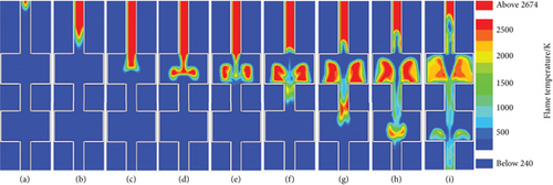
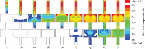
This is the process of gas explosion propagation in the first cavity. When the explosion flame and shock wave enter the cavity, the explosion flame and shock wave expand and dissipate. When they propagate towards the outlet, part of the explosion flame and shock wave outgo from the cavity through the outlet, and the other part is blocked by the cavity walls, forming a reverse flame and reflection wave and propagating in the reverse direction (towards the inlet side). Owing to different reflection angles, some reverse flame and reflection waves outgo from the cavity through the inlet after superposition, and the reverse flame and reflection wave that cannot enter the cavity inlet are blocked by the walls, reflected again and propagate towards the outlet, so repeatedly. In the process, the flame disappears with the depletion of premixed gas, and the shock wave is sent out in batches. Therefore, under the effect of the cavity, the explosion flame and shock wave overpressure are obviously attenuated, realizing the function of flame-out and wave attenuation. The propagation process and the attenuation mechanism of the explosion flame and shock wave in the second cavity are the same as those in the first cavity, which further enhances the effect of explosion propagation suppression.
4. Conclusions
- (1)
The single cavity has an obvious inhibitory effect on the propagation of the shock wave and explosion flame. The experimental results show that the gas explosion flame and shock wave overpressure at the outlet of the single cavity are attenuated by 42.5% and 11%, respectively, compared with those in a straight pipeline without a cavity. The numerical simulation results agree with the experimental results and show that the shock wave overpressure at the outlet of the single cavity decays by 10.61% compared with that in a straight pipeline without a cavity
- (2)
The dual cavity has a better inhibitory effect on the propagation of the shock wave and explosion flame. The experimental results show that the explosion flame and shock wave overpressure at the outlet of the dual cavity are attenuated by 75.4% and 26.7%, respectively, compared with those in a straight pipeline without a cavity. The numerical simulation results agree with the experimental results and show that the shock wave overpressure at the outlet of the dual cavity is attenuated by 28.88%, compared with that in a straight pipeline without a cavity
- (3)
The propagation process of gas explosion in the cavity was simulated, and the mechanism of the inhibitory effect of the cavity on gas explosion propagation was analyzed. After the shock wave and explosion flame enter the cavity, the reflection and superposition occur repeatedly under the effect of the rigid walls of the cavity, and oscillation occurs between the outlet side and the inlet side. In this process, the flame disappears with the depletion of the premixed gas, and the shock wave is sent out in batches. Thus, the function of the flame-out and wave attenuation is realized
Conflicts of Interest
The authors declare that there is no conflict of interest regarding the publication of this paper.
Acknowledgments
This work was supported by the Natural Science Foundation of China [No. 11472007] and the Institute of Energy, Hefei Comprehensive National Science Center [No. 19KZS203].
Open Research
Data Availability
The data can be obtained by contacting Shujie Yuan and Chaomin Mu: [email protected].


